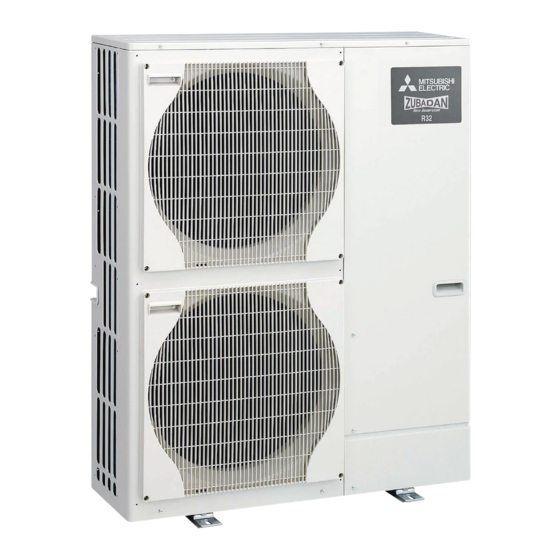
Mitsubishi Electric PUZ-HWM140VHA Service Manual

Mitsubishi Electric PUZ-HWM140VHA Service Manual

Air to water heat pump, outdoor unit, salt proof

Advertisement

AIR TO WATER HEAT PUMP
SERVICE MANUAL
<Outdoor unit>
[Model Name]
PUZ-HWM140VHA
PUZ-HWM140YHA
Salt proof model
PUZ-HWM140VHA-BS
PUZ-HWM140YHA-BS
[Service Ref.]
PUZ-HWM140VHA
PUZ-HWM140YHA
PUZ-HWM140VHA-BS
PUZ-HWM140YHA-BS
R32
Notes:
• This manual describes service
CONTENTS
1. REFERENCE MANUAL ................................... 2
2. SAFETY PRECAUTION ................................... 3
3. SPECIFICATIONS .......................................... 10
4. DATA ............................................................. 13
5. OUTLINES AND DIMENSIONS ..................... 14
6. WIRING DIAGRAM ........................................ 15
7. WIRING SPECIFICATIONS ........................... 17
9. TROUBLESHOOTING ................................... 19
10. DISASSEMBLY PROCEDURE ...................... 68
PARTS CATALOG (OCB748)
August 2020
No. OCH748
data of outdoor unit only.

Advertisement

Table of Contents
loading

Summary of Contents for Mitsubishi Electric PUZ-HWM140VHA

  • Page 1: Table Of Contents

    AIR TO WATER HEAT PUMP August 2020 No. OCH748 SERVICE MANUAL <Outdoor unit> [Service Ref.] [Model Name] Notes: PUZ-HWM140VHA PUZ-HWM140VHA • This manual describes service data of outdoor unit only. PUZ-HWM140YHA PUZ-HWM140YHA Salt proof model PUZ-HWM140VHA-BS PUZ-HWM140VHA-BS PUZ-HWM140YHA-BS PUZ-HWM140YHA-BS CONTENTS 1.
  • Page 2: Reference Manual

    REFERENCE MANUAL MODELS POWER INVERTER PACKAGE TYPE Heat pump REFRIGERANT Model name EHPT20X-MED × × EHPT20X-VM6D × × EHPT20X-YM9D × × EHPT20X-YM9ED × × EHPT20X-TM9D × × EHPT20X-MHEDW × × ERPT20X-MD × × ERPT20X-VM2D × × ERPT20X-VM6D × × EHPT30X-MED ×...
  • Page 3: Safety Precaution

    SAFETY PRECAUTION MEANINGS OF SYMBOLS DISPLAYED ON THE UNIT This mark is for R32 refrigerant only. Refrigerant type is written on nameplate of heat pump unit. WARNING In case that refrigerant type is R32, this unit uses a flammable refrigerant. (Risk of fire) If refrigerant leaks and comes in contact with fire or heating part, it will create harmful gas and there is risk of fire.
  • Page 4 [1] Warning for service (1) Do not alter the unit. (2) For installation and relocation work, follow the instructions in the Installation Manual and use tools and pipe components specifically made for use with refrigerant specified in the outdoor unit installation manual. (3) Ask a dealer or an authorized technician to install, relocate and repair the unit.
  • Page 5 [4] Cautions for unit using R32 refrigerant Pay careful attention to the following points. (1) Information on servicing (1-1) Checks on the Area Prior to beginning work on systems containing flammable refrigerants, safety checks are necessary to ensure that the risk of ignition is minimized.
  • Page 6 (3) Repair to intrinsically Safe Components Do not apply any permanent inductive or capacitance loads to the circuit without ensuring that this will not exceed the permissible voltage and current permitted for the equipment in use. Intrinsically safe components are the only types that can be worked on while live in the presence of a flammable atmos- phere.
  • Page 7 b) Isolate system electrically. c) Before attempting the procedure, ensure that: • mechanical handling equipment is available, if required, for handling refrigerant cylinders; • all personal protective equipment is available and being used correctly; • the recovery process is supervised at all times by a competent person; •...
  • Page 8 2-3. PRECAUTIONS WHEN REUSING EXISTING R22/R410a REFRIGERANT TOOLS Cautions for refrigerant piping work Tools for R32 (The following table shows whether conventional tools can be used or not.) Tools and materials R32 tools Can R22 tools be used? Can R407C tools be used? Can R410a tools be used? ×...
  • Page 9 2-6. Minimum installation area If you unavoidably install a unit in a space where all four sides are blocked or there are depressions, confirm that one of these situations (A, B or C) is satisfied. Note: These countermeasures are for keeping safety not for specification guarantee. A) Secure sufficient installation space (minimum installation area Amin).
  • Page 10: Specifications

    SPECIFICATIONS 3-1. SPECIFICATIONS PUZ-HWM140VHA PUZ-HWM140VHA-BS 1φ, 230 V, 50 Hz 40.1 Heating (A7/W35) Nominal water flow rate (Heating mode) L/min 14.00 Heating y t i ℃ 4.46 (A7/W35) ℃ 3.14 l n i ℃ Heating y t i 14.00 Heating (A2/W35) (A2/W35) 3.15...
  • Page 11 PUZ-HWM140YHA PUZ-HWM140YHA-BS 3φ, 400 V, 50 Hz Nominal water flow rate (Heating mode) L/min 40.1 Heating (A7/W35) Heating y t i 14.00 ℃ 4.46 (A7/W35) ℃ 3.14 l n i ℃ Heating y t i 14.00 Heating (A2/W35) 3.15 (A2/W35) ℃...
  • Page 12 3-2. AVAILABLE RANGE (WATER FLOW RATE, RETURN WATER TEMP.) Notes: • If the value of water flow rate and return water temp. become lower than the available range, it could cause damage to the parts of unit. • Be sure to avoid the unavailable range during defrosting. Otherwise, the outdoor unit is insufficiently defrosted and/or the heat exchanger of the indoor unit may freeze.
  • Page 13: Data

    4-2. STANDARD OPERATION DATA Mode Cooling(A35/W7) Heating(A7/W35) Capacity 11,900 14,000 Total Input 3.97 3.14 Outdoor unit PUZ-HWM140VHA/ PUZ-HWM140YHA Phase, Hz 1 / 3, 50 Electrical circuit Voltage 230 / 400 Current 16.8 / 5.5 13.8 / 4.5 Discharge pressure 2.83 Suction pressure 0.86...
  • Page 14: Outlines And Dimensions

    OUTLINES AND DIMENSIONS PUZ-HWM140VHA(-BS) PUZ-HWM140YHA(-BS) Unit: mm OCH748...
  • Page 15: Wiring Diagram

    WIRING DIAGRAM PUZ-HWM140VHA(-BS) OCH748...
  • Page 16 PUZ-HWM140YHA(-BS) OCH748...
  • Page 17: Wiring Specifications

    WIRING SPECIFICATIONS FIELD ELECTRICAL WIRING (power wiring specifications) Outdoor model name HWM140V HWM140Y Outdoor unit power supply ~/N (single), 50 Hz, 230 V 3N~ (3 ph 4-wires), 50 Hz, 400 V Outdoor unit input capacity Main switch (Breaker) 40 A 16 A Outdoor unit power supply 3 ×...
  • Page 18: Refrigerant System Diagram

    Refrigerant flow in cooling Refrigerant flow in heating Symbol Part name Detail COMP Compressor DC inverter scroll compressor (Mitsubishi Electric Corporation) H/P SW High pressure switch (63H) For protection (OFF: 4.15MPa) Plate HEX Plate Heat Exchanger MWA2-34HM(Mitsubishi Electric Corporation) REV/V...
  • Page 19: Troubleshooting

    TROUBLESHOOTING 9-1. TROUBLESHOOTING <Check code displayed by self-diagnosis and actions to be taken for service (summary)> Present and past check codes are logged, and they can be displayed on the control board of outdoor unit. Actions to be taken for service, which depends on whether or not the trouble is reoccurring in the field, are summarized in the table below. Check the contents below before investigating details.
  • Page 20 9-3. SELF-DIAGNOSIS ACTION TABLE <Abnormalities detected when the power is turned on> Check Code Abnormal point and detection method Cause Judgment and action 1 Check following items. 1 No voltage is supplied to terminal block (TB1) of outdoor unit. a) Power supply breaker a) Power supply breaker is b) Connection of power supply terminal block turned off.
  • Page 21 Check Code Abnormal point and detection method Cause Judgment and action Miswiring of Interface unit/Flow temp. 1 Contact failure or miswiring 1 Check disconnection, looseness or polarity of controller-outdoor unit connecting wire of Interface unit/Flow temp. Interface unit/Flow temp. controller-outdoor 1.
  • Page 22 <Abnormalities detected while unit is operating> Check Code Abnormal point and detection method Cause Judgment and action High pressure (High pressure switch 1 Decreased water flow 1–5 Check water circuit and repair the defect. 63H operated) 2 Clogged filter of water pipe Abnormal if high pressure switch 63H 3 Dirt of plate heat exchanger operated (*) during compressor operation.
  • Page 23 Check Code Abnormal point and detection method Cause Judgment and action Open/short of outdoor unit thermistors 1 Check connection of connector (TH3, TH32, 1 Disconnection or contact failure (TH3, TH32, TH34, TH6, TH7, and TH8) TH34, TH6/TH7) on the outdoor controller of connectors circuit board.
  • Page 24 Check Code Abnormal points and detection method Case Judgment and action To find out the detail history (latest) about U9 error, turn ON SW2-1, 2-2 and 2-6. Detailed codes Refer to "9-9. FUNCTION OF SWITCHES, CONNECTORS AND JUMPERS". Overvoltage error 1 Abnormal increase in power source 1 Check the field facility for the power supply.
  • Page 25 Check Code Abnormal point and detection method Cause Judgment and action Overheat protection 1 Defective outdoor fan (fan 1 Check outdoor unit air passage. Abnormal if outdoor pipe thermistor (TH3) motor) or short cycle of outdoor detects 70°C or more or condensing unit during cooling operation temperature of pressure sensor (63HS) 2 Defective outdoor pipe...
  • Page 26 Check Code Abnormal point and detection method Cause Judgment and action Remote controller control board 1 Defective remote controller 1 Replace remote controller. 1 Abnormal if data cannot be read nor- mally from the nonvolatile memory of the remote controller control board. (Check code: E1) (6201 2 Abnormal if the clock function of remote...
  • Page 27 Check Code Abnormal point and detection method Cause Judgment and action Freezing/overheating protection is working (1) Freezing protection (1) Freezing protection <Cooling mode> (1) Freezing protection <Cooling mode> 1 Reduced water flow Plate HEX Liquid temperature (TH34) 12 Check water piping. ·...
  • Page 28 9-4. TROUBLESHOOTING OF PROBLEMS Phenomena Factor Countermeasure 1. Remote controller display does not 1 12 VDC is not supplied to remote controller. 1 Check LED2 on indoor controller board. work. (1) When LED2 is lit: Check the remote controller wiring for break- ing or contact failure.
  • Page 29 Phenomena Countermeasure ■ These sounds can be heard when refrigerant and/or water is (are) flowing A flowing water sound or occasional hissing sound is heard. in the indoor unit or refrigerant pipe, or when the refrigerant and/or water is (are) chugging. ■...
  • Page 30 Symptoms: “Please Wait” is kept being displayed on the remote controller. Inspection method and Diagnosis flow Cause troubleshooting Check the display time of “Please Wait” after turning on the main power. How long is 6 minutes 2 minutes “Please Wait” or more or less •...
  • Page 31 LED display of the indoor controller board Symptoms: Nothing is displayed on the remote controller. 1 LED1: LED2: LED3: Inspection method and Diagnosis flow Cause troubleshooting Check the voltage between S1 and S2 on the terminal block of the indoor unit which is used to connect the indoor unit and the outdoor unit.
  • Page 32 LED display of the indoor controller board Symptoms: Nothing is displayed on the remote controller. 2 LED1: LED2: LED3: Inspection method and Diagnosis flow Cause troubleshooting Check the voltage between S1 and S2 on the terminal block of the indoor unit which is used to connect the indoor unit and the outdoor unit.
  • Page 33 LED display of the indoor controller board Symptoms: Nothing is displayed on the remote controller. 3 LED1: LED2: LED3: — Inspection method and Diagnosis flow Cause troubleshooting Check the voltage of the terminal block (TB6) of the remote controller. 10 to 16 VDC? •...
  • Page 34 9-5. HOW TO CHECK THE PARTS PUZ-HWM140VHA(-BS) PUZ-HWM140YHA(-BS) Parts name Checkpoints TH3: Liquid pipe temp. Disconnect the connector then measure the resistance with a multimeter. TH4: Discharge temp. (At the ambient temperature of 10 to 30°C) TH6: 2-phase pipe temp.
  • Page 35 <How to check the resistance> Correct the wiring. Is there contact failure? To measure the resistance, connect the negative (−) end of the tester to pin 4. UNIT PUZ-HWM140VHA PUZ-HWM140YHA FAN MOTOR BH61J064 Measuring points Resistance Power supply check Pin 1–pin 4 ∞...
  • Page 36 9-6. HOW TO CHECK THE COMPONENTS 9-6-1. Thermistor feature chart Low temperature thermistors • Thermistor <Liquid> (TH3) • Thermistor <2-phase pipe> (TH6) • Thermistor <Ambient> (TH7) • Thermistor <Suction> (TH32) • Thermistor <Plate Hex liquid> (TH34) Thermistor R0 = 15 k" ± 3% B constant = 3480 ±...
  • Page 37 9-6-2. High pressure sensor Vout (V) MULTI CONTROLLER BOARD 5 VDC MICRO Vout Outdoor controller board PROCESSOR 12 VDC Gray 63HS Drive circuit 3-1: 5 V (DC) 2-1: Output Vout (DC) PRESSURE Orange (MPa) 9-6-3. Linear expansion valve Yellow (1) Operation summary of the linear expansion valve Black •...
  • Page 38 (3) How to attach and detach the coil of linear expansion valve <Composition> Linear expansion valve is separable into the main body and the coil as shown in the diagram below. Main body Stopper Coil Lead wire <How to detach the coil> Hold the lower part of the main body (shown as A) firmly so that the main body does not move and detach the coil by pulling it upward.
  • Page 39 9-7. TEST POINT DIAGRAM Outdoor controller circuit board <CAUTION> TEST POINT 1 is high voltage. PUZ-HWM140VHA(-BS) PUZ-HWM140YHA(-BS) CNDM Manual defrost, 1–2: detect history Input of low-level Operation record reset sound priority mode monitor function Function switch 21S4 4-way valve Model select...
  • Page 40 Outdoor noise filter circuit board PUZ-HWM140VHA(-BS) LI, NI POWER SUPPLY Voltage of 230 VAC is input (Connect to the terminal block (TB1)) CNAC1, CNAC2 230 VAC (Connect to the outdoor controller circuit board) EI, E2, E3, E4 (Connect to the earth)
  • Page 41 Outdoor noise filter circuit board PUZ-HWM140YHA(-BS) CNCT Primary current Connect to the outdoor power circuit board (CN5) Connect to the elec- trical parts box LO1, LO2, LO3 POWER Connect to the elec- SUPPLY trical parts box LO1-LO2/LO2- LO3/LO3-LO1: 400 VAC input CNAC2 Connect to the out- 230 VAC...
  • Page 42 Outdoor power circuit board Brief Check of POWER MODULE If they are short-circuited, it means that they are broken. PUZ-HWM140VHA(-BS) Measure the resistance in the following points (connectors, etc.). 1. Check of POWER MODULE 1 Check of DIODE circuit R - P1 , S - P1, R - N1 , S - N1...
  • Page 43 Outdoor power circuit board Brief Check of POWER MODULE If they are short-circuited, it means that they are broken. PUZ-HWM140YHA(-BS) Measure the resistance in the following points (connectors, etc.). 1. Check of POWER MODULE 1.Check of DIODE circuit L1 - P1 , L2 - P1 , L3 - P1 , L1 - N1 , L2 - N1 , L3 - N1 2.Check of INVERTER circuit P2 - U , P2 - V , P2 - W , N2 - U , N2 - V , N2 - W Note: The marks, L1 , L2 , L3 , N1 , N2 , P1 , P2 , U , V and W...
  • Page 44 Outdoor converter circuit board PUZ-HWM140YHA(-BS) L1-IN, N-IN L1-A1 CK-OU Connect to the noise filter Connect to the ACL1 Connect to the CK capacitor circuit board (LO1, NO) Connect to the outdoor power circuit board (CN7) L1-A2, L2-A2, L3-A2 L1-OU, L2-OU, L3-OU Connect to the ACL1, ACL2, ACL3 Connect to the outdoor power circuit board (TB-L1, L2, L3)
  • Page 45 9-8. OUTDOOR UNIT OPERATION MONITOR FUNCTION PUZ-HWM140VHA PUZ-HWM140YHA PUZ-HWM140VHA-BS PUZ-HWM140YHA-BS <Display function of inspection for outdoor unit> The blinking patterns of both LED1 (green) and LED2 (red) indicate the types of abnormality when it occurs. Types of abnor- mality can be indicated in details by connecting an optional part “A-Control Service Tool (PAC-SK52ST)” to connector CNM on outdoor controller board.
  • Page 46 Indication Error Detailed Outdoor controller board reference Check Contents Inspection method page code* LED1 (Green) LED2 (Red) 3 blinking 1 blinking Abnormality of discharging 1 Check if stop valves are open. temperature (TH4) and Comp. 2 Check if connectors (TH4, LEV-A, and LEV-B) on outdoor con- P.22 surface temperature (TH33) troller board are not disconnected.
  • Page 47 <Outdoor unit operation monitor function> [When optional part 'A-Control Service Tool (PAC-SK52ST)' is connected to outdoor controller board (CNM)] Digital indicator LED1 displays 2 digit number or code to inform operation condition and the meaning of check code by control- ling DIP SW2 on “'A-Control Service Tool'”.
  • Page 48 ■ The black square ( ) indicates a switch position. SW2 setting Display detail Explanation for display Unit Pipe temperature/Liquid (TH3) −40 to 90 −40 to 90 (When the coil thermistor detects 0°C or below, “–” and temperature are displayed by turns.) (Example) When −10°C;...
  • Page 49 ■ The black square ( ) indicates a switch position. SW2 setting Display detail Explanation for display Unit Pipe temperature/Liquid (TH3) on error −40 to 90 occurring (When the coil thermistor detects 0°C or below, “–” −40 to 90 and temperature are displayed by turns.) °C (Example) When −15°C;...
  • Page 50 ■ The black square ( ) indicates a switch position. SW2 setting Display detail Explanation for display Unit Outdoor unit setting information • The tens digit (Total display for applied setting) Setting details Display details H·P / Cooling only 0: H·P 1: Cooling only Single phase / 3 phase 0: Single phase 2: 3 phase Code...
  • Page 51 ■ The black square ( ) indicates a switch position. SW2 setting Display detail Explanation for display Unit Secondary LEV opening pulse 0 to 500 0 to 500 (When it is 100 pulse or more, hundreds digit, tens Pulse Heating: LEV-A digit and ones digit are displayed by turns.) 2 3 4 5 6 Cooling: LEV-B...
  • Page 52 ■ The black square ( ) indicates a switch position. SW2 setting Display detail Explanation for display Unit Return water temperature on error 0 to 100 occurring °C 0 to 100 2 3 4 5 6 Plate HEX liquid pipe thermistor (TH34) −40 to 90 on error occurring (When the temperature is 0°C or less, “–”...
  • Page 53 ■ The black square ( ) indicates a switch position. SW2 setting Display detail Explanation for display Unit Comp. surface temperature (TH33) −52 to 221 −52 to 221 (When the temperature is 0°C or less, "–" and tem- perature are displayed by turns.) (When the discharge thermistor detects 100°C or Code more, hundreds digit, tens digit, and ones digit are...
  • Page 54 <Service check mode:SW7-2 ON Backup data> ■ The black square ( ) indicates a switch position. SW2 setting Display detail Explanation for display Unit The primary current when the last error 0 to 50 occurred 0 to 50 2 3 4 5 6 The DC bus voltage when the last error 100 to 1023 occurred...
  • Page 55 ■ The black square ( ) indicates a switch position. SW2 setting Display detail Explanation for display Unit The fan step when the second-to-last 0 to 16 error occurred 0 to 16 Step 2 3 4 5 6 The return water temperature (THW2) 0 to 60 when the second-to-last error occurred 0 to 60...
  • Page 56 ■ The black square ( ) indicates a switch position. SW2 setting Display detail Explanation for display Unit The heat sink temperature (TH8) when −40 to 200 the second-to-last error occurred (When it is 0 or less, “–” and numbers are displayed °C −40 to 200 by turns.)
  • Page 57 ■ The black square ( ) indicates a switch position. SW2 setting Display detail Explanation for display Unit The plate HEX liquid pipe tempera- −39 to 88 ture (TH2) when the third-to-last error Plate HEX liquid pipe temperature (TH34) occurred Σ(TH34(N))/n °C −39 to 88...
  • Page 58 ■ The black square ( ) indicates a switch position. SW2 setting Display detail Explanation for display Unit The operation mode when the fourth-to- This setting shows the operation mode when the last error occurred fourth-to-last error occurred as well as the default set- ting (Please refer to the following).
  • Page 59 ■ The black square ( ) indicates a switch position. SW2 setting Display detail Explanation for display Unit The outdoor 2-phase pipe tempera- −39 to 88 ture (TH6) when the fourth-to-last error (When it is 0 or less, “–” and numbers are displayed occurred by turns.) °C...
  • Page 60 9-9. FUNCTION OF SWITCHES PUZ-HWM140VHA(-BS) PUZ-HWM140YHA(-BS) ■ The black square ( ) indicates a switch position. Action by the switch operation Type of Switch Function Effective timing Switch Manual defrost Start Normal When compressor is working in heat operation Abnormal history clear...
  • Page 61 SPECIAL FUNCTION 9.9.1. Low noise mode (on-site modification) (Fig. 9-9-1) 1. Using the CNDM connector (Option) CNDM Orange By performing the following modification, operation noise of the outdoor unit can be reduced. Brown The low noise mode will be activated when a commercially available timer or the contact input of an ON/OFF switch is added to the CNDM connector (option) on the control board of the outdoor unit.
  • Page 62 9-10. Request code list Certain indoor/outdoor combinations do not have the request code function; therefore, no request codes are displayed. Refer to indoor unit service manual for how to use the controllers and request codes for indoor unit. Description Request content Unit Remarks (Display range)
  • Page 63 Description Request content Unit Remarks (Display range) Outdoor unit-Control state Refer to 9-10-1.Detail Contents in Request Code. ― Compressor-Frequency control state Refer to 9-10-1.Detail Contents in Request Code. ― Outdoor unit-Fan control state Refer to 9-10-1.Detail Contents in Request Code. ―...
  • Page 64 Description Request content Unit Remarks (Display range) 103 Error history 1 (latest) Displays error history. (" --" is displayed if no history is present.) Code 104 Error history 2 (second to last) Displays error history. (" --" is displayed if no history is present.) Code 105 Error history 3 (third to last) Displays error history.
  • Page 65 9-10-1. Detail Contents in Request Code [Operation state] (Request code : "0") Relay output state Data display Power currently Display Compressor 4-way valve Solenoid valve supplied to compressor – – – – Relay output state Operation mode Operation mode Display Operation mode STOP •...
  • Page 66 [Actuator output state] (Request code : "54") Data display Actuator output state 1 Actuator output state 2 Actuator output state Actuator output state Compressor is Display 4-way valve Compressor Display warming up [Error content (U9)] (Request code : "55 ") Data display Error content 1 Error content 2...
  • Page 67 [Outdoor unit – Setting information] (Request code: "71") Setting information 1 Data display Display Defrost mode Setting information 1 Standard Setting information 2 For high humidity Setting information 2 Single-/ Heat pump/ Display cooling only 3-phase Heat pump Single-phase Cooling only Heat pump 3-phase Cooling only...
  • Page 68: Disassembly Procedure

    DISASSEMBLY PROCEDURE PUZ-HWM140VHA(-BS) PUZ-HWM140YHA(-BS) : Indicates the visible parts in the photos/figures. NOTE: Turn OFF the power supply before disassembly. OPERATING PROCEDURE PHOTOS/FIGURES Photo 1 1. Removing the service panel and top panel Top panel fixing screws (1) Remove 3 service panel fixing screws (5 × 12) and slide the Top panel hook on the right downward to remove the service panel.
  • Page 69 OPERATING PROCEDURE PHOTOS/FIGURES Photo 4 (PUZ-HWM140Y) 3. Removing the electrical parts box (1) Remove the service panel. (Refer to procedure 1) (2) Remove the top panel. (Refer to procedure 1) Controller circuit (3) Disconnect the indoor/outdoor connecting wire and board (C.B.) Noise filter circuit power supply wire from terminal block.
  • Page 70 OPERATING PROCEDURE PHOTOS/FIGURES 4. Disassembling the electrical parts box Photo 8 (PUZ-HWM140Y) Electrical (1) Disconnect all the connectors on the controller circuit board. parts box (2) Remove the 3 screws, screw 1, 2 and 3, that fix the plate equipped with the outdoor controller circuit board, and the electrical parts box, screw 1 from the front and the screw 2 and 3 from the bottom of the electrical parts box.
  • Page 71 OPERATING PROCEDURE PHOTOS/FIGURES Photo 13 5. Removing the thermistor <Plate HEX liquid> (TH34) and thermistor <Ambient> (TH7) (1) Remove the service panel. (Refer to procedure 1) (2) Remove the top panel. (Refer to procedure 1) (3) Disconnect the connectors, TH7/34 (red) on the control- ler circuit board in the electrical parts box.
  • Page 72 Note1: When removing the parts for refrigerant circuit, take out the refrigerant soon after removing the service panel. Note2: Recover refrigerant without spreading it in the air. Note3: When installing the 4-way valve, the LEV, the pressure switch (63H) and the high pressure switch (63HS), cover it with a wet cloth to prevent it from heating (120°C or more for the 4-way valve and the LEV/ 100°C or more for 63H and 63HS), then braze the pipes so that the inside of pipes are not oxidized.
  • Page 73 OPERATING PROCEDURE PHOTOS/FIGURES Photo 20 13. Removing the plate heat exchanger Heat exchanger (1) Remove the electrical parts box. (Refer to procedure 4) (2) Remove 3 valve bed fixing screws (4 × 10), 2 valve and fixing screws (5 × 16) then remove the valve bed. (3) Remove cover panel (front) fixing screws (2 for front/5 ×...
  • Page 74 O-ring and grease which are used in Cylinder unit (e.g. EHST20C series) . Quick fastener O-ring HEAD OFFICE: TOKYO BUILDING, 2-7-3, MARUNOUCHI, CHIYODA-KU, TOKYO 100-8310, JAPAN Copyright 2020 MITSUBISHI ELECTRIC CORPORATION Published: Aug. 2020 No. OCH748 Made in Japan Specifications are subject to change without notice.

This manual is also suitable for:

Puz-hwm140yhaPuz-hwm140vha-bsPuz-hwm140yha-bs

Table of Contents