Advertisement
Table of Contents
- 1 Table of Contents
- 2 Reference Manual
- 3 Safety Precaution
- 4 Parts Names and Functions
- 5 Specifications
- 6 Noise Criterion Curves
- 7 Outlines and Dimensions
- 8 Wiring Diagram
- 9 Refrigerant System Diagram
- 10 Troubleshooting
- 11 Function Setting
- 12 Special Function
- 13 Disassembly Procedure
- 14 Remote Controller
- Download this manual
SPLIT-SYSTEM HEAT PUMP
SERVICE MANUAL
Indoor unit
[Model Name]
[Service Ref.]
PCA-A24KA8
PCA-A24KA8
PCA-A30KA8
PCA-A30KA8
PCA-A36KA8
PCA-A36KA8
PCA-A42KA8
PCA-A42KA8
INDOOR UNIT
ON
RETURN SELECT
MENU
HOLD
OFF
WIRED REMOTE
CONTROLLER
(Option)
Model name
indication
WIRELESS REMOTE
CONTROLLER (Option)
CONTENTS
1. REFERENCE MANUAL ................................... 2
2. SAFETY PRECAUTION ................................... 3
3. PARTS NAMES AND FUNCTIONS ................. 6
4. SPECIFICATIONS ........................................... 7
5. NOISE CRITERION CURVES ......................... 9
6. OUTLINES AND DIMENSIONS ...................... 10
7. WIRING DIAGRAM ......................................... 12
8. REFRIGERANT SYSTEM DIAGRAM ............ 13
9. TROUBLESHOOTING ................................... 14
10. FUNCTION SETTING ..................................... 28
11. SPECIAL FUNCTION ..................................... 29
12. DISASSEMBLY PROCEDURE ....................... 32
13. REMOTE CONTROLLER ............................... 38
PARTS CATALOG (TCB113)
May 2023
No. TCH113
Advertisement
Table of Contents

Related Manuals for Mitsubishi Electric PCA-A24KA8


Summary of Contents for Mitsubishi Electric PCA-A24KA8
-
Page 1: Table Of Contents
SPLIT-SYSTEM HEAT PUMP May 2023 No. TCH113 SERVICE MANUAL Indoor unit [Model Name] [Service Ref.] PCA-A24KA8 PCA-A24KA8 PCA-A30KA8 PCA-A30KA8 PCA-A36KA8 PCA-A36KA8 PCA-A42KA8 PCA-A42KA8 CONTENTS 1. REFERENCE MANUAL ........2 2. SAFETY PRECAUTION ........3 3. PARTS NAMES AND FUNCTIONS ....6 4. -
Page 2: Reference Manual
REFERENCE MANUAL OUTDOOR UNIT SERVICE MANUAL Model Name Service Ref. Service Manual No. / Parts catalog No. PUZ-A24/30NHA7 PUZ-A24/30NHA7 PUZ-A36/42NKA7 PUZ-A36/42NKA7 OCH636 / OCB636 PUY-A24/30NHA7 PUY-A24/30NHA7 PUY-A36/42NKA7 PUY-A36/42NKA7 PUZ-A24/30NHA8 PUZ-A24/30NHA8 PUZ-A36/42NKA8 PUZ-A36/42NKA8 OCH764 / OCB764 PUY-A24/30NHA8 PUY-A24/30NHA8 PUY-A36/42NKA8 PUY-A36/42NKA8 PUZ-HA24NHA1 PUZ-HA24NHA1 PUZ-HA30/36NKA PUZ-HA30/36NKA... -
Page 3: Safety Precaution
SAFETY PRECAUTION 2-1. ALWAYS OBSERVE FOR SAFETY Before obtaining access to terminal, all supply circuits must be disconnected. 2-2. CAUTIONS RELATED TO NEW REFRIGERANT Cautions for units utilising refrigerant R410A Precautions during the repair service. Preparation before the repair service. •... - Page 4 [1] Warning for service (1) Do not alter the unit. (2) For installation and relocation work, follow the instructions in the Installation Manual and use tools and pipe components specifically made for use with refrigerant specified in the outdoor unit installation manual. (3) Ask a dealer or an authorized technician to install, relocate and repair the unit.
- Page 5 Unit Electronic weighing scale [4] Service tools Use the below service tools as exclusive tools for R410A refrigerant. Tool name Specifications · Use the existing fitting specifications . (UNF1/2) Gauge manifold · Use high-tension side pressure of 5.3MPa·G [768.7 PSIG] or over. Charge hose ·...
-
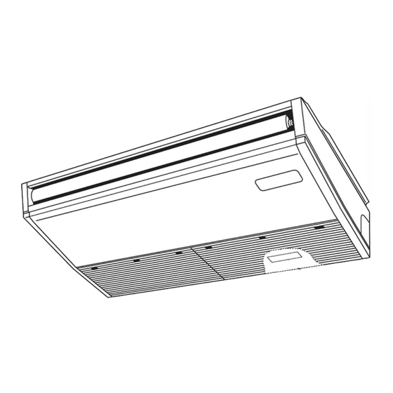
Page 6: Parts Names And Functions
PARTS NAMES AND FUNCTIONS Louver Air outlet Vane Filter (Inside of Air intake) Air intake TCH113... -
Page 7: Specifications
SPECIFICATIONS PCA-A24KA8 Service Ref. Power supply(phase, cycle, voltage) 1 phase, 60 Hz, 208/230 V Max. Fuse Size Min.Circuit Ampacity External finish White Munsell 6.4Y 8.9/0.4 Heat exchanger Plate fin coil Fan(drive) × No. Sirocco fan (direct) × 3 0.095 Fan motor output Fan motor 1.25... - Page 8 Service Ref. PCA-A42KA8 Power supply(phase, cycle, voltage) 1 phase, 60 Hz, 208/230 V Max. Fuse Size Min.Circuit Ampacity External finish White Munsell 6.4Y 8.9/0.4 Heat exchanger Plate fin coil Fan(drive) × No. Sirocco fan (direct) × 4 Fan motor output 0.160 Fan motor F.L.A...
-
Page 9: Noise Criterion Curves
NOISE CRITERION CURVES PCA-A24KA8 PCA-A30KA8 NOTCH SPL(dB) LINE NOTCH SPL(dB) LINE High High Medium1 Medium1 Medium2 Medium2 NC-70 NC-70 NC-60 NC-60 NC-50 NC-50 NC-40 NC-40 NC-30 NC-30 APPROXIMATE APPROXIMATE THRESHOLD OF THRESHOLD OF HEARING FOR NC-20 HEARING FOR NC-20 CONTINUOUS... -
Page 10: Outlines And Dimensions
OUTLINES AND DIMENSIONS PCA-A24KA8 PCA-A30KA8 Unit: inch (mm) TCH113... - Page 11 PCA-A36KA8 PCA-A42KA8 Unit: in (mm) TCH113...
-
Page 12: Wiring Diagram
WIRING DIAGRAM PCA-A24KA8 PCA-A30KA8 PCA-A36KA8 PCA-A42KA8 TCH113... -
Page 13: Refrigerant System Diagram
REFRIGERANT SYSTEM DIAGRAM PCA-A24KA8 PCA-A30KA8 PCA-A36KA8 PCA-A42KA8 Strainer Heat exchanger Refrigerant GAS pipe connection (Flare) Condenser/evaporator temperature thermistor (TH5) Refrigerant flow in cooling Refrigerant flow in heating Refrigerant LIQUID pipe connection (Flare) Pipe temperature thermistor/liquid Room temperature (TH2) thermistor (TH1) -
Page 14: Troubleshooting
TROUBLESHOOTING 9-1. TROUBLESHOOTING <Check code displayed by self-diagnosis and actions to be taken for service (summary)> Present and past check codes are logged, and they can be displayed on the wired remote controller and control board of out- door unit. Actions to be taken for service, which depends on whether or not the trouble is reoccurring in the field, are summa- rized in the table below. - Page 15 [Output pattern A] Errors detected by indoor unit Wired remote Wireless remote controller controller Beeper sounds/OPERATION Symptom Remark INDICATOR lamp blinks Check code (Number of times) Intake sensor error P2, P9 Pipe (liquid or 2-phase pipe) sensor error E6, E7 Indoor/outdoor unit communication error Float switch connector open Drain pump error...
- Page 16 • On wireless remote controller The continuous buzzer sounds from receiving section of indoor unit. Blink of operation lamp • On wired remote controller 1 Check code displayed in the LCD. *The check code in the parenthesis indicates PAR-41MAA model. ●...
- Page 17 Note: 9-3. SELF-DIAGNOSIS ACTION TABLE Errors to be detected in outdoor unit, such as codes starting with F, U or E (excluding E0 to E7), are not covered in this document. Please refer to the outdoor unit service manual for the details. Check code Abnormal point and detection method Cause...
- Page 18 Check code Abnormal point and detection method Cause Countermeasure Freezing/overheating protection is work- (Cooling or drying mode) (Cooling or drying mode) 1 Clogged filter (reduced airflow) 1 Check clogs of the filter. 1 Freezing protection (Cooling mode) 2 Short cycle of air path 2 Remove shields.
- Page 19 Check code Abnormal point and detection method Cause Countermeasure Condenser/evaporator temperature ther- 1 Defective thermistor 1–3 Check resistance value of thermistor. mistor (TH5) characteristics For characteristics, refer to (P1) above. 1 The unit is in 3-minute resume protec- 2 Contact failure of connector 2 Check contact failure of connector (CN44) tion mode if short/open of thermistor is (CN44) on the indoor controller...
- Page 20 Check code Abnormal point and detection method Cause Countermeasure Remote controller transmission 1 2 remote controllers are set as 1 Set a remote controller to main, and the error(E3)/signal receiving error(E5) “main.” other to sub. (In case of 2 remote con- 1 Abnormal if remote controller could not find blank of transmission path for 6 sec- trollers)
- Page 21 9-4. TROUBLESHOOTING OF PROBLEMS Note: Refer to the outdoor unit's service manual for the detail of remote controller. Phenomena Cause Countermeasure (1)LED2 on indoor controller board • When LED1 on indoor controller board is also off. is off. Power supply of rated voltage is not supplied to out- Check the voltage of outdoor power door unit.
- Page 22 Note: Refer to the outdoor unit's service manual for the detail of remote controller. Phenomena Cause Countermeasure (3)Upward/downward vane The vane is not downward during defrosting and heat Normal operation (The vane is set to hori- performance failure preparation and when the thermostat is OFF in HEAT zontal regardless of remote control.) mode.
- Page 23 9-5. EMERGENCY OPERATION 9-5-1. When wireless remote controller fails or its battery is exhausted When the remote controller cannot be used When the batteries of the remote controller run out or the remote control- ler malfunctions, the Emergency Operation can be done using the emer- gency buttons on the grille.
- Page 24 9-6. HOW TO CHECK THE PARTS PCA-A24KA8 PCA-A30KA8 PCA-A36KA8 PCA-A42KA8 Parts name Check points Room temperature Disconnect the connector then measure the resistance with a tester. thermistor (TH1) (At the ambient temperature 50 to 86˚F [10 to 30˚C] ) Pipe temperature...
- Page 25 9-6-1. Thermistor <Thermistor characteristic graph> <Thermistor for lower temperature> Room temperature thermistor (TH1) Thermistor for Pipe temperature thermistor/liquid (TH2) lower temperature Condenser/evaporator temperature thermistor (TH5) Thermistor R =15 k ± 3% " Fixed number of B=3480 ± 2% t( )Rt=15exp { 3480( 273+t T-32 273+...
- Page 26 9-7. TEST POINT DIAGRAM Indoor controller board PCA-A24KA8 PCA-A30KA8 PCA-A36KA8 PCA-A42KA8 LED3 Transmission (Indoor/outdoor) Vane motor output (MV) 12 V pulse output CN2L CN90 Connector (LOSSNAY) Connector to the wireless remote controller board (CNB) Model selection CN4Y i-See sensor (option)
- Page 27 9-8. FUNCTIONS OF DIP SWITCH AND JUMPER WIRE Each function is controlled by the DIP switch and the jumper wire on indoor controller board. PCA-A24KA8 PCA-A30KA8 PCA-A36KA8 PCA-A42KA8 ■ The black square ( ) indicates a switch position. Jumper wire (...
-
Page 28: Function Setting
FUNCTION SETTING 10-1. UNIT FUNCTION SETTING BY THE REMOTE CONTROLLER Each function can be set as necessary using the remote controller. The setting of function for each unit can only be done by the remote controller. (1) Functions available when setting the unit number to 00 Refer to the service manual that comes with each outdoor unit. -
Page 29: Special Function
SPECIAL FUNCTION 11-1. Rotation Function (and back-up function, 2nd stage cut-in function) This function is only available when using wired remote controller. 11-1-1. Operation (1) Rotation function (and Back-up function) Outline of functions · Main and sub units operate alternately according to the interval of rotation setting. Note: Main and sub unit should be set by refrigerant address. - Page 30 System constraint · This function is available only in cooling mode. Ex.) Set temp. by R/C = 68°F [20:] [2nd stage cut-in function]··· Request code number "322–324" Set point = 79°F [26:] When request code number is “323”. Room temp. ] Set point Room temp.
- Page 31 11-2. BACK-UP HEATING FUNCTION 11-2-1. Operation The back-up heater turns ON when both of the following conditions have been satisfied: A) When the room temperature has not risen after the heater ON delay time has passed. Note: The heater ON delay time starts when the condition of “set temperature − room temperature > 1°F [0.5 ]”...
-
Page 32: Disassembly Procedure
DISASSEMBLY PROCEDURE PCA-A24KA8 PCA-A30KA8 Be careful when removing heavy parts. PCA-A36KA8 PCA-A42KA8 (Photo: PCA-A36KA8) OPERATING PROCEDURE PHOTOS & ILLUSTRATIONS Figure 1 1. Removing the air intake grille (1) Slide the air intake grille holding knobs (at 2 or 3 loca- tions) to the rear to open the air intake grille. - Page 33 OPERATING PROCEDURE PHOTOS 3. Removing the room temperature thermistor (TH1) Photo 4 (1) Remove the air intake grille. (See Figure 1, 2) Casing (2) Remove the beam by removing 1 screw (4 8 PT) (See × Photo 1) (3) Remove 2 screws from the electrical cover, and remove the electrical cover.
- Page 34 OPERATING PROCEDURE PHOTOS & ILLUSTRATIONS 5. Removing the fan (3 connection) Photo 9 (1) Remove the air intake grille. (See Figure 1, 2) (2) Remove the beam by removing 1 screw (4 8 PT) (See × Photo 1) (3) Remove 2 screws from the electrical cover, and remove the electrical cover.
- Page 35 OPERATING PROCEDURE PHOTOS Photo 12 7. Removing the vane motor (1) Remove the air intake. (See Figure 1, 2) Connector Vane motor and cover (2) Remove the right side panel. (See Figure 3, 4) (3) Remove the connector of vane motor. (4) Remove 2 screws of vane motor cover, then remove vane motor.
- Page 36 OPERATING PROCEDURE PHOTOS Photo 17 10. Removing the pipe temperature thermistor/liquid (TH2) and the condenser/evaporator temperature thermistor (TH5) (1) Remove the air intake grille. (See Figure 1, 2) (2) Remove the left and right side panels. (See Figure 3, 4) (3) Remove the under panel.
- Page 37 OPERATING PROCEDURE PHOTOS Photo 21 13. Removing the heat exchanger (1) Remove the air intake grille. (See Figure 1, 2) (2) Remove the left and right side panels. (See Figure 3, 4) (3) Remove the under panel. (See Photo 13) (4) Remove the drain pan.
-
Page 38: Remote Controller
REMOTE CONTROLLER 13-1. REMOTE CONTROLLER FUNCTIONS <PAR-41MAA> Controller interface The functions of the function buttons change depending on the screen. Refer to the button function guide that appears at the bottom of the LCD for the functions they serve on a given screen. When the system is centrally controlled, the button function guide that corresponds to the locked button will not appear. - Page 39 Display The main display can be displayed in two different modes: “Full” and “Basic”. The initial setting is “Full”. To switch to the “Basic” mode, change the setting on the Main display setting. (Refer to operation manual included with remote controller.) <Full mode>...
- Page 40 Menu structure Main menu Press the button. MENU Move the cursor to the desired item with the buttons, and press the button. SELECT/HOLD Operation Vane · Louver · Vent. (Lossnay) High power Comfort Manual vane angle 3D i-See sensor Timer menu Timer ON/OFF timer Auto-OFF timer...
- Page 41 Continue from the previous page. Maintenance menu Error information Filter information Cleaning Auto descending panel Descending operation Descending adjustment Service menu Test run menu Test run Drain pump test run Maintenance information Model name input Serial No. input Dealer information input Initialize maintenance info.
- Page 42 Main menu list Main Setting and display items Setting details menu Operation Vane · Louver · Vent. Use to set the vane angle. (Lossnay) • Select a desired vane setting. Use to turn ON/OFF the louver. • Select a desired setting from "ON" and "OFF." Use to set the amount of ventilation.
- Page 43 Setting and display Main menu Setting details items Initial Display Main display Use to switch between "Full" and "Basic" modes for the Main display, and use setting setting to change the background colors of the display to black. Display de- Make the settings for the remote controller related items as necessary.
- Page 44 <PAR-SL101A-E> Controller interface Transmission area Remote controller display Set Temperature buttons OFF/ON button Mode button (Changes operation mode) Fan Speed button (Changes fan speed) Airfl ow button (Changes up/ i-see button* down airfl ow direction) Timer ON button Menu button Timer OFF button SET/SEND button Weekly timer ON/OFF button*...
- Page 45 13-2. ERROR INFORMATION When an error occurs, the following screen will appear. Check the error status, stop the operation, and consult your dealer. 1. Check code, error unit, refrigerant address, model name, and serial Error information number will appear. Error code The model name and serial number will appear only if the information Error unit Unit#1...
- Page 46 • Checking the error information Maintenance menu While no errors are occurring, page 2/2 of the error information can be Error information viewed by selecting "Error information" from the Maintenance menu. Filter information Errors cannot be reset from this screen. Cleaning Main menu: RETURN Cursor...
- Page 47 13-3. SERVICE MENU Maintenance password is required 1. Select "Service" from the Main menu, and press the [SELECT/HOLD] button. Main Main menu *At the main display, the menu button and select "Service" to make the Service maintenance setting. 2. When the Service menu is selected, a window will appear asking for the pass- Service menu word.
- Page 48 13-4. TEST RUN 13-4-1. PAR-41MAA 1. Select "Service" from the Main menu, and press the [SELECT/HOLD] button. Test run Input maintenance info. Settings Check Select "Test run" with the F1 or F2 button, and press the [SELECT/HOLD] button. Others : RETURN SELECT MENU RETURN...
- Page 49 13-4-2. PAR-SL101A-E 1. Press the button to stop the air conditioner. • If the weekly timer is enabled ( is on), press the button to disable it ( is off). 2. Press the button for 5 seconds. • comes on and the unit enters the service mode. 3.
- Page 50 13-5. FUNCTION SETTING Settings menu 13-5-1. PAR-41MAA Function setting 1. Select "Service" from the Main menu, and press the [SELECT/HOLD] button. Select "Setting" from the Service menu, and press the [SELECT/HOLD] button. Service menu: MENU Select "Function setting", and press the [SELECT/HOLD] button. SELECT MENU RETURN...
- Page 51 13-5-2. PAR-SL101A-E 1. Going to the function select mode Press the button between of 5 seconds. (Start this operation from the status of remote controller display turned off.) [CHECK] is lit and "00" blinks. (Fig. 1) Press the button to set the "50". Direct the wireless remote controller toward the receiver of the indoor unit and press the button.
- Page 52 13-6. ERROR HISTORY 1. Select "Service" from the Main menu, and press the [SELECT/HOLD] button. Test run Input maintenance info. Settings Check Others : RETURN Select "Check" with the F1 or F2 button, and press the [SELECT/HOLD] button. SELECT MENU RETURN HOLD 2.
- Page 53 13-7. SELF-DIAGNOSIS 13-7-1. PAR-41MAA 1. Select "Service" from the Main menu, Diagnosis and press the [SELECT/HOLD] button. Self check Remote controller check Select "Check" from the Service menu, and press the [SELECT/HOLD] button. Service menu: MENU Cursor Select "Diagnosis" from the Check menu, and press the [SELECT/HOLD] button.
- Page 54 13-7-2. PAR-SL101A-E 1. Press the button 1 to stop the air conditioner. is on), press the button 3 is off). to disable it ( 2. Press the button 2 for 5 seconds. 3. Press the button 5 to select the refrigerant address (M-NET address) B of the indoor 4.
- Page 55 13-8. REMOTE CONTROLLER CHECK If operations cannot be completed with the remote controller, diagnose the remote controller with this function. 1. Select "Service" from the Main menu, and Diagnosis press the [SELECT/HOLD] button. Self check Remote controller check Select "Check" from the Service menu, and press the [SELECT/HOLD] button.
- Page 56 13-9. SMOOTH MAINTENANCE Check menu 1. Select "Service" from the Main menu, and press the [SELECT/HOLD] button. Error history Diagnosis Smooth maintenance Request code Select "Check" with the F1 or F2 button, and press the [SELECT/HOLD] button. Service menu: MENU Cursor Select "Smooth maintenance"...
- Page 57 ■ Refrigerant address Single refrigerant system Multi refrigerant system (group control) In the case of single refrigerant system, the refrigerant address Up to 16 refrigerant systems (16 outdoor units) can be con- is "00" and no operation is required. nected as a group by 1 remote controller. To check or set the Simultaneous twin, triple units belong to this category refrigerant addresses.
- Page 58 HEAD OFFICE: TOKYO BUILDING, 2-7-3, MARUNOUCHI, CHIYODA-KU, TOKYO 100-8310, JAPAN MITSUBISHI ELECTRIC CONSUMER PRODUCTS (THAILAND) CO., LTD. 700/406 MOO 7, TAMBON DON HUA ROH, AMPHUR MUANG, CHONBURI 20000 THAILAND Published: May 2023. No. TCH113 Specifications are subject to change without notice.
Need help?
Do you have a question about the PCA-A24KA8 and is the answer not in the manual?
Questions and answers