Advertisement
Table of Contents
- 1 Table of Contents
- 2 Reference Manual
- 3 Safety Precaution
- 4 Specifications
- 5 Data
- 6 Outlines and Dimensions
- 7 Wiring Diagram
- 8 Wiring Specifications
- 9 Refrigerant System Diagram
- 10 Troubleshooting
- 11 Monitoring the Operation Data by the Remote Controller
- 12 Disassembly Procedure
- Download this manual
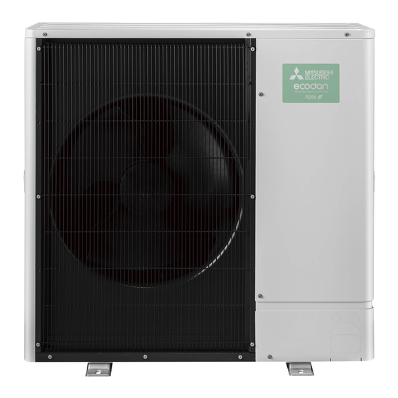
AIR TO WATER HEAT PUMP UNITS
SERVICE MANUAL
[Model Name]
PUZ-SWM60VAA
PUZ-SWM80VAA
PUZ-SWM100VAA
PUZ-SWM120VAA
PUZ-SWM140VAA
PUZ-SWM80YAA
PUZ-SWM100YAA
PUZ-SWM120YAA
PUZ-SWM140YAA
PUZ-SHWM60VAA
PUZ-SHWM80VAA
PUZ-SHWM100VAA
PUZ-SHWM120VAA
PUZ-SHWM140VAA
PUZ-SHWM80YAA
PUZ-SHWM100YAA
PUZ-SHWM120YAA
PUZ-SHWM140YAA
OUTDOOR UNIT
R32
[Service Ref.]
PUZ-SWM60VAA.TR
PUZ-SWM80VAA.TR
PUZ-SWM100VAA.TR
PUZ-SWM120VAA.TR
PUZ-SWM140VAA.TR
PUZ-SWM80YAA.TR
PUZ-SWM100YAA.TR
PUZ-SWM120YAA.TR
PUZ-SWM140YAA.TR
PUZ-SHWM60VAA.TR
PUZ-SHWM80VAA.TR
PUZ-SHWM100VAA.TR
PUZ-SHWM120VAA.TR
PUZ-SHWM140VAA.TR
PUZ-SHWM80YAA.TR
PUZ-SHWM100YAA.TR
PUZ-SHWM120YAA.TR
PUZ-SHWM140YAA.TR
REVISED EDITION-A
Note:
• This manual describes
Revision:
• Added connectable indoor
units in REVISED
EDITION-A.
OCH809 is void.
CONTENTS
1. REFERENCE MANUAL ································ 2
2. SAFETY PRECAUTION ······························· 3
3. SPECIFICATIONS ······································ 11
4. DATA ··························································· 13
5. OUTLINES AND DIMENSIONS·················· 16
6. WIRING DIAGRAM ····································· 17
7. WIRING SPECIFICATIONS ························ 21
8. REFRIGERANT SYSTEM DIAGRAM ········ 22
9. TROUBLESHOOTING ································ 24
BY THE REMOTE CONTROLLER ············· 68
11. DISASSEMBLY PROCEDURE ··················· 73
PARTS CATALOG (OCB809)
December 2023
No. OCH809
service data of the outdoor
units only.
Advertisement
Table of Contents

Summarization of Contents
1. Reference Manual
1-1. Indoor Unit Service Manual
Manuals for various indoor units.
2. Safety Precautions
2-1. General Safety Observances
Essential safety rules to follow before and during repair.
2-2. Refrigerant R32 Safety Cautions
Specific safety guidelines for handling R32 refrigerant.
[1] Warning for Service
Critical warnings for unit installation, relocation, and servicing.
[4] Cautions for R32 Refrigerant Units
Detailed safety checks and procedures for R32 refrigerant units.
[5] Service Tools for R32 Refrigerant
Lists essential tools specifically designed for R32 refrigerant.
2-3. Reusing Existing R22/R410A Refrigerant Pipes
(1) Flowchart for Pipe Reuse Determination
Determines if existing pipes can be used and if a filter drier is needed.
(2) Refrigerant Piping Work Cautions
Guidelines for piping work, including thickness and flare nut dimensions.
4. Data
4-1. Refilling Refrigerant Charge
Provides data for refilling refrigerant charge based on piping length.
4-2. Compressor Technical Data
Lists winding resistance values for compressor models.
4-3. Noise Criterion Curves
Presents noise level data across different frequencies for various operating modes.
8. Refrigerant System Diagram
Refrigerant Collecting (Pump Down)
Step-by-step procedure for safely collecting refrigerant before servicing.
9. Troubleshooting
9-1. Troubleshooting Summary
Overview of check codes and general actions for troubleshooting.
9-2. Self-Diagnosis Action Table
Details causes and actions for self-diagnosis errors detected at power-on.
Abnormalities Detected During Operation
Lists operational abnormalities, their detection methods, causes, and remedies.
Check Code Abnormal Point and Detection Method
Details error codes, abnormal points, causes, and judgments.
9-3. Troubleshooting of Problems
Addresses common operational issues and their troubleshooting steps.
9-4. How to Check Parts
Provides resistance measurement guidelines for checking electronic components.
9-5. How to Check Components
Details methods for checking the DC fan motor and pressure sensor.
(1) Linear Expansion Valve Operation Summary
Explains the operation and connection of linear expansion valves.
9-6. Test Point Diagram
Illustrates the locations of test points on the outdoor controller circuit board.
9-7. Function of Switches, Connectors and Jumpers
Explains the function and settings of DIP switches and connectors.
9.7.1. Low Noise Mode
Details how to activate low noise mode via on-site modification.
9.7.2. Demand Function
Explains how to activate demand function for energy saving.
Display Function of Inspection for Outdoor Unit
Describes how to interpret LED indicators for unit status and abnormalities.
SW2 Setting for Diagnostic Display
Explains how to use SW2 settings to display operating parameters and error histories.
SW2 Setting for Backup Data Display
Details how to use SW2 to view backup data for past errors.
10. Monitoring Operation Data via Remote Controller
10-1. Request Code List
Lists codes to request and monitor operational data from the remote controller.
10-1-1. Detail Contents in Request Code
Provides detailed explanations for various request codes related to unit operation.
11. Disassembly Procedure
Operating Procedure: Removing Service and Top Panels
Step-by-step guide for removing the outer panels of the unit.
Operating Procedure: Removing Fan Motor
Instructions for safely removing the fan motor assembly.
Operating Procedure: Removing Electrical Parts Box
Guide for disassembling the electrical parts box.
Operating Procedure: Removing Compressor (MC)
Detailed steps for removing the compressor unit.


Need help?
Do you have a question about the PUZ-SWM100VAA and is the answer not in the manual?
Questions and answers