Table of Contents
Advertisement
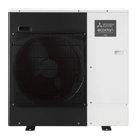
AIR TO WATER HEAT PUMP UNITS
SERVICE MANUAL
<Outdoor unit>
[Model Name]
PUZ-WM50VHA
PUZ-WM60VAA
PUZ-WM85VAA
PUZ-WM85YAA
PUZ-WM112VAA
PUZ-WM112YAA
Salt proof model
PUZ-WM50VHA-BS
PUZ-WM60VAA-BS
PUZ-WM85VAA-BS
PUZ-WM85YAA-BS
PUZ-WM112VAA-BS
PUZ-WM112YAA-BS
PUZ-WM50VHA.UK
[Service Ref.]
PUZ-WM50VHA.UK
PUZ-WM60VAA.UK
PUZ-WM85VAA.UK
PUZ-WM85YAA.UK
PUZ-WM112VAA.UK
PUZ-WM112YAA.UK
PUZ-WM50VHA-BS.UK
PUZ-WM60VAA-BS.UK
PUZ-WM85VAA-BS.UK
PUZ-WM85YAA-BS.UK
PUZ-WM112VAA-BS.UK
PUZ-WM112YAA-BS.UK
R32
CONTENTS
1. REFERENCE MANUAL ································ 2
2. SAFETY PRECAUTION ······························· 3
3. SPECIFICATIONS ······································ 10
4. DATA ··························································· 12
5. OUTLINES AND DIMENSIONS·················· 13
6. WIRING DIAGRAM ····································· 15
7. WIRING SPECIFICATIONS ························ 18
8. REFRIGERANT SYSTEM DIAGRAM ········ 19
9. TROUBLESHOOTING ································ 22
11. DISASSEMBLY PROCEDURE ··················· 66
PARTS CATALOG (OCB727)
March 2020
No. OCH727
Note:
• This manual describes
service data of the outdoor
units only.
Advertisement
Table of Contents
Troubleshooting

Summarization of Contents
Reference Manual
Air to Water System Models
Lists model names and their corresponding service references for air to water systems.
Safety Precautions
General Safety Observations
General safety guidelines to follow before accessing unit terminals.
R32 Refrigerant Cautions
Specific safety measures for units using R32 refrigerant during service.
Service Warnings and Cautions
Important warnings and precautions for service personnel, including handling refrigerants.
Specifications
Model Specifications
Detailed technical specifications for various outdoor unit models, including power, current, and components.
Operating Range Charts
Charts showing available operating ranges for water flow rate and return water temperature.
Data
Noise Criterion Curves
Graphs illustrating noise levels across different frequency bands for various models.
Outlines and Dimensions
Unit Dimensions and Clearances
Visual representations of unit dimensions, required service space, and installation clearances.
Wiring Diagram
Electrical Wiring Diagrams
Schematic diagrams illustrating electrical connections for various unit models.
Wiring Specifications
Power Wiring Specifications
Details on wire sizes, circuit ratings, and power supply requirements for electrical wiring.
Refrigerant System Diagram
Refrigerant Flow Diagrams
Schematic diagrams illustrating the refrigerant flow path in heating and cooling modes for different models.
Troubleshooting
Self-Diagnosis and Error Codes
Guides for interpreting self-diagnosis check codes and identifying abnormalities.
Component Testing Procedures
Methods for testing specific components like thermistors, motors, and valves using resistance and voltage checks.
Switch, Connector, and Jumper Functions
Explains the function and setting of DIP switches, connectors, and jumpers on the control boards.
Monitoring the Operation Data by the Remote Controller
Request Code List for Operation Data
A comprehensive list of request codes used to retrieve operation data from the remote controller.
Detailed Data Request Contents
Detailed explanations of data points and their meanings for various request codes.
Disassembly Procedure
Removing Panels and Fan Motor
Procedures for removing outer panels, service panels, and the fan motor assembly.
Removing Electrical Components and Boards
Steps to remove electrical parts box, boards, thermistors, sensors, valves, and switches.
Removing Compressor and Receiver
Detailed steps for removing the compressor, receiver, and associated piping.
Removing Heat Exchanger and Reactor
Procedures for removing the plate heat exchanger, reactor, and pressure relief valve.


Need help?
Do you have a question about the PUZ-WM112YAA and is the answer not in the manual?
Questions and answers