Advertisement
Quick Links
Have this manual in the palm of
your hand by FG Finder application.
WARNING
BEFORE INSTALLING THE CONTROLLER, WE RECOMMEND READING THROUGH THE
ENTIRE INSTRUCTION MANUAL IN ORDER TO AVOID POSSIBLE DAMAGE TO THE
PRODUCT
PRECAUTIONS WHEN INSTALLING THE PRODUCT:
Before performing any procedure on this instrument, disconnect it from the mains;
Ensure that the instrument has adequate ventilation and avoid installation in panels containing
devices that may cause it to operate outside the specified temperature limits;
Install the product away from sources that may generate electromagnetic disturbances such as:
motors, contactors, relays, solenoid valves, etc;
SERVIÇO AUTORIZADO:
A instalação ou manutenção do produto deve ser realizado somente por profissionais qualificados;
ACESSÓRIOS:
Utilize apenas acessórios originais Full Gauge Controls.
Em caso de dúvidas, entre em contato com o suporte técnico.
POR ESTAR EM CONSTANTE EVOLUÇÃO, A FULL GAUGE CONTROLS RESERVA-SE O DIREITO DE
ALTERAR AS INFORMAÇÕES CONTIDAS NO MANUAL A QUALQUER MOMENTO, SEM PRÉVIO AVISO.
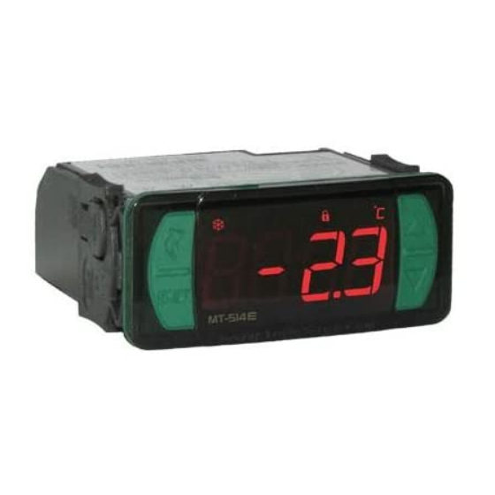
1. DESCRIPTION
e
The MT-514
FASTON is a temperature controller for cooling or heating applications. It has an
internal audible alarm (buzzer) and an output for alarm control that can also be configured for electric
defrost, hot gas defrost, fan or as a second compressor that will act in parallel with the main one. The
minimum and maximum temperature record is displayed at the touch of a single key
available feature is the shutdown of control functions, making it possible for the MT-514
FASTON to operate only as a temperature indicator. And through an intelligent function blocking
system, it prevents unauthorized persons from changing the control parameters.
Product is compliant with UL Inc. (United States and Canada).
2. APPLICATION
• Vaccine refrigerators
• Refrigerated counters
• Freezers rooms
• Hot counters
• Greenhouses
3. TECHNICAL SPECIFICATIONS
Power supply
Control temperature
Operating temperature
Load current (outputs)
Operating humidity
Dimensions (WxHxD)
Dimensions of the clipping for fixing
of the instrument
(*) This instrument measures and controls temperatures of up to 200°C/392°F, using the silicone sensor cable SB59
(sold separately).
Note: The sensor cable lenght can be increased by the user up to 200 meters using PP 2 x 24 AWG cable.
4. INDICAÇÕES E TECLAS
Defrost indication LED
Heating indication LED
*Cooling indication LED
Quick Access
Menu Key (Flatec)
Set key
e
MT-514
* Blinking led (when [,F26] = 7): Indicates that OUT1 has been activated and the compressor delay is occurring
before trigger OUT2
5. WIRING DIAGRAM
5.1. Identifications (see Images I to IV)
- Image I: MT-512E 2HP Faston, supplied at 115 Vac.
- Image II: MT-512E 2HP Faston, supplied at 230 Vac.
- Image III: MT-512EL 2HP Faston, supplied at 12 Vac/dc.
- Image IV: MT-512EL 2HP Faston, supplied at 24 Vac/dc.
e
MT-514
FASTON
DIGITAL CONTROLLER FOR HEATING OR COOLING
WITH DEFROST AND CONFIGURABLE
ALARM OUTPUT
Connector
Audible
Defrost
Function
for quick
Alarm
blocking
coupling
;
(Flatec). Another
MT-514 E Faston: 115 or 230 Vac ±10%(50/60 Hz)
MT-514 EL Faston: 12 or 24 Vac/dc +10%
-50 to 105ºC (-58 to 221°F)*
0 to 50 ºC / 32 to 122°F
OUT1: 16(12)A 250Vac 2HP
OUT2: 10A / 240Vac 1/4HP
10 to 90%RH (without condensation)
76 x 34 x 84 mm
71 ± 0,5 x 29 ± 0,5 mm (see item 5)
Alarm indication LED
Functions lock indication LED
Temperature unit indication LED
IP 65
FRONT
Control
Serial
Protection
functions
Programming
level
shutdown
ATTENTION
FOR INSTALLATIONS WHERE A SEALING IS REQUIRED TO AVOID LIQUID CONTACT, THE CUT FOR THE
CONTROLLER MUST BE OF 70,5X29mm MAXIMUM. THE SIDE LOCKS MUST BE FIXED SO IT PRESSES THE
RUBBER SEALING AVOIDING INFILTRATION BETWEEN THE CUT AND THE CONTROLLER.
Image I
Image II
Image III
e
Image IV
NEW CONNECTION SYSTEM (QUICK COUPLING):
CONNECTION:
- Hold the wire near its end and insert it into the
desired slot.
- If necessary, press the bottom to assist the
connection.
NOTE:
- In the Push-In connectors the maximum wire
gauge that can be used is 1.5mm².
- The wires must be tinned or use Rocket Pin
terminals with a maximum gauge of 0.75mm².
5.2. Temperature sensor connection
- Connect the sensor S1 wires to terminals "1 and 2" spring type connector. The polarity is not relevant.
- Length of the sensor cables can be increased by user himself to up to 200 meters, using a PP 2x24
AWG cable.
5.3. Recommendations of IEC60364 standard
a) Install overload protectors in the controller supply.
b) Install transient suppressors – suppressor filter RC – in the circuit to increase the service life of the
controller relay. See connection instructions of the filter on the previous page.
Increase key
c) The sensor cables may be together, but not in the same conduit where the power supply of the
controller and/or of the loads passes through.
6. FIXING PROCEDURE
Decrease key
a) Cutout the panel plate (Image V - item 13) where the controller will be fixed, with dimensions
X = 71±0,5 mm and Y = 29±0,5 mm;
b) Remove the side locks (Image VI - item 13): To do this, squeeze the elliptical central part (with the
Logo Full Gauge Controls) and move the latches back;
c) Pass the wires through the cutout of the plate (image VII - Item 13) and make the electrical installation
as described in item 6;
d) Insert the controller into the panel cutout, from the outside in;
e) Replace the latches and push then until they are pressed against the panel, securing the controller to
the housing (see arrow in Figure VI - item 13);
f) Adjust the parameters as described in item 9.
WARNING: for installations requiring liquid-tight sealing, the cut-off for the installation of the
controller should be at must 70.5x29mm. The side latches must be secured so that they press
the rubber sealing to prevent infiltration between the cutout and the controller.
e
e
M T- 51 4
M T- 51 4
POWER
NC
SUPPLY
7
8
9 10 11 12 13 14
1
2 3 4
5 6
D1
SENSOR
POWER
NC
SUPPLY
7
8
9 10 11 12 13 14
1
2 3 4
5 6
D1
SENSOR
POWER
NC
SUPPLY
7
8
9 10 11 12 13 14
1
2 3 4
5 6
D1
SENSOR
0
12Vac/dc
POWER
NC
SUPPLY
7
8
9 10 11 12 13 14
1
2 3 4
5 6
D1
SENSOR
0
24Vac/dc
FASTON and PUSH-IN FAST
BOTTOM
WIRE INPUT
DISCONNECT:
- To disconnect the cord, press the bottom and
remove it.
The wire should be picked
in 5 mm and tinned.
Terminal Rocket Pin.
evolution
E251415
NO
115 Vac
Alimentação da carga
NO
230 Vac
Power supply
NO
Power supply
NO
Power supply
Advertisement

Related Manuals for Full Gauge Controls MT-514 E Faston


Summary of Contents for Full Gauge Controls MT-514 E Faston
- Page 1 Utilize apenas acessórios originais Full Gauge Controls. Em caso de dúvidas, entre em contato com o suporte técnico. Image II POR ESTAR EM CONSTANTE EVOLUÇÃO, A FULL GAUGE CONTROLS RESERVA-SE O DIREITO DE SENSOR ALTERAR AS INFORMAÇÕES CONTIDAS NO MANUAL A QUALQUER MOMENTO, SEM PRÉVIO AVISO.
- Page 2 Vinyl protector - Image IX (item 13) 7.3.3. Functions lockdown Protects the controller should when installed in a place with splashing water, such as in refrigerated The use of the functions lockdown brings greater security to the operation of the instrument. When it is counters.
-
Page 3: Parameter Table
[Rc1,] F06 - Output control differential (Hysteresis) ( 7.5. Parameter table It is the difference in temperature (hysteresis) between TURNING ON and OFF the cooling (or heating) CELSIUS FAHRENHEIT when recipe ([rc1,]) is used. Description Max Unit Default Max Unit Default Example: One wants to control the temperature at 4.0 °C with a differential of 1.0 °C. - Page 4 F24 - Low temperature alarm: F35 - Digital input operation mode: It is the temperature below that which the instrument will visually display the low temperature alarm Select the operatiing mode of the digital input. [atlo] as well as the audible alarm (Buzzer). The differential for switching off the alarm is fixed at [no,,]- Disabled [,,,1]- Digital input: Door open (active when closing contact) 0.1°C / 1°F.
- Page 5 Extension Frame The Full Gauge Controls extension frame allows the installation of Evolution / Ri line with measures 76x34x77 mm (dimensions of the clipping for fixing in the extension frame is 71x29mm) in varied situations, since it eliminates precision cut to embed the instrument. Allows customization via a sticker with...
-
Page 6: Environmental Information
If in doubt, please contact Full Gauge Controls. Products manufactured by Full Gauge Controls, as of May 2005, have a two (02) year warranty, as of the date of the consigned sale, as stated on the invoice. They are guaranteed against manufacturing defects that make them unsuitable or inadequate for their intended use.