Table of Contents
Advertisement
Available languages
Available languages
Quick Links
Fluchttür-Steuerterminal
Fluchttür-Steuerterminal
Produktname
1340-14/-15/-20/-21
Produktname
Installations- und Montageanleitung
Installations- und Montageanleitung
D0131500
DXXXXXNN
N
A
O
U
T
F
assaabloyopeningsolutions.de
DE Seite
EN Page
Experience a safer
Experience a safer
and more open world
and more open world
2
38
Advertisement
Chapters
Table of Contents

Related Manuals for Assa Abloy effeff 1340-20


Summary of Contents for Assa Abloy effeff 1340-20
- Page 1 Fluchttür-Steuerterminal assaabloyopeningsolutions.de DE Seite EN Page Produktname Fluchttür-Steuerterminal Produktname 1340-14/-15/-20/-21 Installations- und Montageanleitung Installations- und Montageanleitung Experience a safer Experience a safer DXXXXXNN D0131500 and more open world and more open world...
- Page 2 Dokumentennummer, -datum D0131500 09.2021 Copyright © 2021, ASSA ABLOY Sicherheitstechnik GmbH Diese Dokumentation einschließlich aller ihrer Teile ist urheberrechtlich geschützt. Jede Verwertung bzw. Veränderung außerhalb der engen Grenzen des Urheberrechtsgesetzes ist ohne Zustimmung von ASSA ABLOY Sicherheitstechnik GmbH unzulässig und strafbar.
-
Page 3: Table Of Contents
Inhaltsverzeichnis Hinweise ..........5 Zu dieser Anleitung. - Page 4 Dauerentriegelung ............25 Dauerhaft entriegeln .
-
Page 5: Hinweise
Hinweise Zu dieser Anleitung Diese Anleitung wurde für Elektrofachkräfte geschrieben. Lesen Sie diese Anleitung, um das Gerät sicher zu installieren, zu betreiben und die zulässigen Einsatzmöglichkeiten, die es bietet, auszunutzen. Für die Prüfung der korrekten Montage und Installation, die Erstinbetriebnahme und Wartung werden weitergehende Kenntnisse zum Produkt benötigt, die nicht in dieser Anleitung beschrieben werden. -
Page 6: Sicherheitshinweise
Genehmigung. Lebensgefahr durch fehlerhafte Inbetriebnahme: Um die Produktsicherheit zu gewährleisten, muss die Inbetriebnahme durch eine sachkundige Person durchgeführt werden. ASSA ABLOY Sicherheitstechnik GmbH bietet Schulungen zur Aneignung der erforderlichen Sachkunde an. Lebensgefahr durch fehlerhafte Wartung: Die Verantwortung für eine korrekte Installation und Funktionskontrolle des Produkts und angeschlossener Kompo- nenten liegt beim Betreiber. -
Page 7: Bestimmungsgemäßer Gebrauch
Unterputz-Wandmontage in einer passenden Einputzdose geeignet. Die Montage, Installation, Inbetriebnahme, Konfiguration und Wartung des Produkts muss von einer Elektrofachkraft durchgeführt werden, mit von ASSA ABLOY zertifizierter Sachkunde zu Fluchttürsteuerungen gemäß den bauaufsichtlichen Anforderungen an elektrischen Verriegelungen von Türen in Rettungswegen. Die Elektrofachkraft ist verpflichtet, die anerkannten Regeln der Technik, Prüfverord-... -
Page 8: Das Fluchttür-Steuerterminal 1340
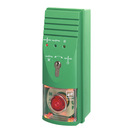
Das Fluchttür-Steuerterminal 1340 Allgemein Das Fluchttür-Steuerterminal 1340 (Abb. 1) ist zur Steuerung und Überwachung einer einzelnen Fluchttür konzipiert. Es beinhaltet die gesamte Steuerelektronik, so dass kein zusätzliches Steuergerät benötigt wird. Alle relevanten Bedien- und Kontrollelemente sind im Steuerterminal integriert und müssen daher nicht zusätzlich extern angeschlossen werden. -
Page 9: Modelle 1340-14/-15/-20/-21
Modelle 1340-14/-15 und 1340-20/-21 Eigenschaften: · Betriebsart als Einzelgerät (Stand-Alone-Betrieb). Das Steuerterminal über- nimmt die komplette Steuerung und Überwachung der Fluchttür. · Freischaltung der Fluchttür über die integrierte Nottaste. · Externe Freischaltung der Fluchttür, zum Beispiel durch eine Brandmeldeanlage. · Dauerentriegelung über den internen Schlüsseltaster oder durch einen exter- nen Kontakt, zum Beispiel durch eine Schaltuhr. -
Page 10: Montage
Montage Vorschriften Gemäß der „Richtlinie über elektrische Verriegelungssysteme von Türen in Rettungswegen“ muss das Terminal so positioniert werden, dass sich die NOT-AUF-Taste innerhalb des Bereichs zwischen 850 mm und 1200 mm über Oberkante Fertigfußboden befindet. Empfohlen wird dort eine Höhe von 850 mm zur Mitte der NOT-AUF-Taste. -
Page 11: Vorbereitende Arbeiten
Vorbereitende Arbeiten Das Fluchttür-Steuerterminal ist in unmittelbarer Nähe der Fluchttür zu montie- ren. Es ist für die Wandmontage vorgesehen. Um baulichen Anforderungen gerecht zu werden, steht eine Aufputz-(AP) und eine Unterputz-(UP) Ausführung zur Verfügung. Der UP-Ausführungen liegt zusätzlich eine Einputzdose aus verzinktem Stahlblech und ein Zubehörbeutel mit Montagematerial bei. -
Page 12: Öffnen Des Gehäuses
Öffnen des Gehäuses Gehäuseoberteil abnehmen Schalten Sie den elektrischen Strom ab. Nehmen Sie die transparente Kunststoffabdeckung ab (Abb. 3– Entfernen Sie den Aufkleber NOT-AUF (– Lösen sie die Schrauben (– Nehmen Sie das Gehäuseoberteil vorsichtig ab (– Die Flachbandleitung, welche die Platinen im Gehäuseoberteil und -unterteil verbindet, muss eventuell gelöst werden. -
Page 13: Wandmontage
Wandmontage Aufputz montieren (Abb. 3 und Abb. 4–1) Nehmen Sie das Gehäuseoberteil vorsichtig ab („Gehäuseoberteil abneh- men“, Seite 12). Fertigen Sie die Bohrlöcher mit Hilfe der Borschablone (Download unter: https://aa-st.de/file/d00076, Impressum Seite 2). Schrauben Sie das Gehäuseunterteil fest. Setzen Sie das Gehäuseoberteil wieder auf. Unterputz montieren Die Unterputzmontage erfolgt in einer geeigneten Einputzdose in der Wand. -
Page 14: Auswechseln Des Profilhalbzylinder
Auswechseln des Profilhalbzylinder Bei Bedarf kann der Profilhalbzylinder (Schließzylinder) ausgetauscht werden. In das Fluchttür-Steuerterminal können nur Profilhalbzylinder der Bauform 90~ links mit einer Länge von 30 mm bis 35 mm eingesetzt werden. Abb. 5: Rückansicht des Terminal-Oberteils Wechseln des Profilhalbzylinders Schalter 90°... -
Page 15: Den Profilzylinder Auswechseln
Den Profilzylinder auswechseln Schalten Sie den elektrischen Strom ab. Nehmen Sie das Gehäuseoberteil vorsichtig ab. („Gehäuseoberteil abneh- men“, Seite 12). Ziehen Sie die Flachbandleitung ab, die die Leiterplatte im Gehäuseoberteil mit der des Gehäuseunterteils verbindet. · Ziehen Sie am Stecker, keinesfalls an der Flachbandleitung, da diese beschä- digt werden kann. -
Page 16: Konfiguration
Konfiguration Anschlussplan Abb. 6 : Anschlusspan Potenzialfreier Relaiskontakt max. 24 V/1A Modelle 1340-20/-21 Data Keine Brandmeldeanlage angeschlossen: Brücke einbauen. Anschluss der Brandmeldeanlage nach EltVTR. Bei Anschluss einer Brandmeldeanlage nach DIN EN 13637:2015: Über 1386BMA-01 Anschlussmodul Brandmeldeanlage, 24 VDC siehe Anleitung D00470 Verriegelungselemente Je nach Produktvariante (12 V oder 24 V): Wählen Sie die Betriebsspannung des Verriegelungselements passend zur... -
Page 17: Einstellmöglichkeiten Am Fluchttür-Steuerterminal
Einstellmöglichkeiten am Fluchttür-Steuerterminal Abb. 7 : Schaltelemente Steckbrücken / Jumper (Tab. 1) und Anschlüsse DIP-Schalter S4 (Tab. 2) 1 2 3 4 5 Drehschalter S3 (Tab. 5) Drehschalter S2 (Tab. 4) Drehschalter S1 (Tab. 3) Tab. 1 Steckbrücken Funktion JP-1 und JP-2 gesteckt Voralarm eingeschaltet: Ein akustischer Voralarm wird vor (Abb. - Page 18 Betriebesart 1: Stand-Alone-Betrieb – Modelle 1340-14/-15 Betriebesart 2: Bus-Betrieb – Modelle 1340-20/-21 Tab. 2 DIP Schalter S4 Funktion DIP-Schalter S4 Türöffnungszeitüberwachung aktiv mit Alarm. (Abb. 7) werkseitig Schalter oben: ON Kein Voralarm bzw. Alarm durch die Schalter unten: OFF Türöffnungszeitüberwachung Die Kurzzeitfreigabe ist mit dem internen Schlüsseltaster, werkseitig über die Klemme 20 oder durch den externen Taster möglich.
- Page 19 Tab. 3 Drehschalter S1 Freigabezeit einstellen Drehschalter S1 11 bis 176 Sekunden (11-Sekunden-Raster) (Abb. 7) Bei einer Kurzzeitfreigabe erfolgt die Entriegelung der Tür für die Kurzzeitfreigabe am Drehschalter S1 eingestellt Zeit. Danach wird die geschlosse- ne Tür wieder verriegelt. Falls die Tür nicht geschlossen ist, wird der zuerst der Voralarm ausgelöst und danach der Alarm.
- Page 20 Die Beleuchtung des NOT-AUF-Schalters können Sie über die DIP-Schalter auf der Beleuchtungsplatine wie folgt einstellen (Tab. 6, Abb. 8): Tab. 6 Dip-Schalter Beleuchtung am Not-Auf-Schalter einstellen DIP-Schalter auf der Beleuchtungsplatine Die Beleuchtung ist ausgeschaltet. Leuchtet grün, wenn die Tür entriegelt ist. Ist dunkel, wenn die Tür entriegelt ist.
-
Page 21: Betriebsart 2 - Busbetrieb
Betriebsart 2 – Busbetrieb nur bei Modell Die Betriebsart wird über DIP-Schalter S4–5 (Tab. 2) eingestellt. 1340-20/-21 Auch wenn das Fluchttür-Steuerterminal in der Betriebsart 2 am TS-Bus in Verbindung mit einem Bus-Steuerungstableau 925 betrieben wird, erfolgt die Steuerung und Überwachung der Fluchttür über das Steuerterminal. Der gesamte bereits beschriebene Funktionsumfang des Steuerterminals sowie der Ablauf der einzelnen Funktionen stehen auch im Busbetrieb zur Verfügung. - Page 22 Tab. 7 Adressbereich einstellen Drehschalter S3 Adressbereich einstellen . . . nicht zulässig Tab. 8 Adresse einstellen Drehschalter S2 zum eingestellten Enzelladressen Adressbereich addieren Einschränkung einstellen Nicht bei Drehschalter S3 auf Position 0 ..+ 10 + 11 Nicht bei Drehschalter S3 auf Position 7 + 12...
-
Page 23: Inbetriebnahme
Inbetriebnahme Einbau und Betrieb von elektrischen Verriegelungen in Fluchtwegen unterliegen bauaufsichtlichen Regelungen, deren Einhaltung vom Installierenden und vom Betreiber sichergestellt werden müssen. Vor der ersten Inbetriebnahme Vor der ersten Inbetriebnahme eines elektrischen Fluchttürverriegelungssys- tems muss der ordnungsgemäße Einbau aller Elemente und deren elektri- scher Anschluss überprüft werden. -
Page 24: Bedienung
Bedienung Kurzzeitfreigabe Eine verriegelte Tür kann über die Funktion Kurzzeitfreigabe für die am Drehschal- ter S1 (Tab. 3, Seite 19) eingestellte Zeit entriegeln werden. Die grüne LED blinkt bei einer Kurzzeitfreigabe im Verhältnis 9:1. Entriegeln Die Kurzzeitfreigabe wird aktiviert · durch Betätigen des Schlüsseltasters in Richtung Verriegeln oder ·... -
Page 25: Dauerentriegelung
Dauerentriegelung Die Tür kann dauerhaft entriegelt werden. Die grüne LED leuchtet dauerhaft bei einer Dauerentriegelung. Dauerhaft entriegeln Die Dauerentriegelung wird aktiviert · durch Betätigen des Schlüsseltasters in Richtung Entriegeln. Tab. 1, Seite 17). oder · durch Ansteuern über die Klemmen 19 oder ·... -
Page 26: Überwachung Der Türöffnungszeit
Überwachung der Türöffnungszeit Die Öffnungszeit der Tür wird vom Fluchttür-Steuerterminal überwacht. Betriebsart 1 Die maximale Dauer der Kurzzeitfreigabe wird am Drehschalter S1 (Tab. 3, Kurzzeitfreigabe Seite 19) eingestellt. Die maximale Dauer des Voralarms wird am Drehschalter S2 (Tab. 4, Seite 19) eingestellt. Die Dauer des akustischen Alarms wird am Dreh- Voralarm ... -
Page 27: Brandmeldeanlage
Brandmeldeanlage Am Fluchttürsteuerterminal eine Brandmeldeanlage (Ruhestromschleife) an den Klemmen 13/14 angeschlossen werden. Bei einem Brandmeldealarm wird die Tür sofort entriegelt. Ein akustischer Alarm kann über den DIP-Schalter S4–4 aktiviert werden. Achtung! Fehlfunktion, wenn der Brandmeldekontakt nicht geschlossen ist: Wird kein Brandmeldeanlage angeschlossen, so müssen die Anschlussklemmen 13/14 mit einer Drahtbrücke geschlossen werden. -
Page 28: Alarm
Alarm Bei einem Alarm · ist die Tür entriegelt, aber nicht bei Sabotage. · ist das akustische Signal für die am Drehschalter S3 (Tab. 5, Seite 19) einge- stellte Dauer aktiv, · ist das Relais Alarm (Abb. 6, Seite 16) geschlossen, · die LEDs signalisieren den Alarm. Folgende Alarme werden nach Ursache unterschieden: ·... -
Page 29: Einen Alarm Beenden
Einen Alarm beenden Betätigen Sie den Schlüsseltasters in Richtung Entriegeln. Quittieren Der akustische Alarm wird beendet. Die grüne LED blinkt im Verhältnis 1:1. Die gelbe LED erlischt. Das Relais Alarm (Abb. 6, Seite 16) ist geöffnet. Der Alarm ist weiterhin aktiv. ... -
Page 30: Wartung Und Überprüfung
· eine jährliche Überprüfung der Türen in Rettungswegen mit elektrischen Verrie- gelungen durchführen. · über die wiederkehrende Prüfung eine Bescheinigung ausstellen, die der Betrei- ber der Bauaufsichtsbehörde auf Verlangen vorzulegen hat. Zertifizierung ASSA ABLOY Sicherheitstechnik GmbH Sicherheitstechnik GmbH Werk Albstadt EltVTR Bildstockstraße 20... - Page 31 Technische Daten...
-
Page 32: Technische Daten
Technische Daten Elektrische Daten 12 V Bezeichnung Wert Nennspannung 12 V DC (±10 %) SELV Eigenstromaufnahme max. 200 mA Nennstromaufnahme für externe max. 1 A Verbraucher Sicherung F1 1,6 A träge (Kleinstsicherung Serie 372/374; Wickmann, Typ TR.5) Sicherung F2 0,1 A träge (Kleinstsicherung Serie 372/374;... -
Page 33: Elektrische Daten 24 V
Elektrische Daten 24 V Bezeichnung Wert Nennspannung 24 V DC (±10 %) SELV Eigenstromaufnahme max. 150 mA Nennstromaufnahme für externe max. 650 mA Verbraucher Sicherung F1 1,0 A träge (Kleinstsicherung Serie 372/374; Wickmann, Typ TR.5) Sicherung F2 0,1 A träge (Kleinstsicherung Serie 372/374;... -
Page 34: Gewährleistung, Entsorgung
Gewährleistung, Entsorgung assaabloyopeningsolutions.de Gewährleistung Es gelten die gesetzlichen Gewährleistungsfristen und die Verkaufs- und Lieferbe- dingungen der ASSA ABLOY Sicherheitstechnik GmbH(assaabloyopeningsolutions.de). Entsorgung Entsorgung nach EPD (Environmental Product Declaration). Verpackungsmaterialien müssen der Wiederverwendung zugeführt werden. WEEE-Reg.-Nr. DE 69404980 Das Produkt ist nach dem Gebrauch als Elektronikschrott ordnungsgemäß zu entsorgen und zur stofflichen Wiederverwendung einer örtlichen Sammelstelle... - Page 35 Checkliste – Prüfung vor der Erstinbetriebnahme...
-
Page 36: Checkliste - Prüfung Vor Der Erstinbetriebnahme
Checkliste – Prüfung vor der Erstinbetriebnahme Montage und Installation Prüfen und dokumentieren Sie die ordnungsgemäße Montage und Installation aller Komponenten im Fluchtweg. Verwenden Sie dazu das von ASSA ABLOY Sicherheitstechnik zur Verfügung gestellte Prüfbuch (D01350xx, Seite 2). Funktionsprüfung Verriegelung prüfen und dokumentieren Schließen Sie die Tür. -
Page 37: Dauerentriegelung Prüfen Und Dokumentieren
Dauerentriegelung prüfen und dokumentieren Aktivieren Sie die Dauerentriegelung. Bezeichnung Nein Die Tür ist entriegelt (manuell prüfen)? Die Tür kann ohne erheblichen Kraftaufwand geöffnet werden? Die grünen LEDs leuchten? Betätigen Sie die Nottaste. Bezeichnung Nein ... - Page 38 D0131500 09/2021 Copyright © 2021, ASSA ABLOY Sicherheitstechnik GmbH This document and all its parts are copyrighted. Any use or changes outside the strict limits of the copyright are prohibited and liable to prosecution unless prior consent has been obtained from ASSA ABLOY Sicherheitstechnik GmbH .
- Page 39 Table of contents Notes ..........41 About this manual .
- Page 40 Permanent release............61 Permanent unlocking .
-
Page 41: Notes
Notes About this manual This manual was written for qualified electricians. Read this manual to install and operate the device safely and make full use of the permitted range of applications the control terminal has to offer. Further knowledge of the product is required for the inspection of correct mounting and installation, commissioning and maintenance, which is not described in this manual. -
Page 42: Safety Instructions
Danger to life due to faulty commissioning: In order to ensure the safety of the product, commissioning must be performed by a qualified person. ASSA ABLOY Sicherheitstechnik GmbH offers training for qualification in the requisite skills. -
Page 43: Intended Use
It must be possible to disconnect the device from the power supply circuit at any time using an easily accessible energy-isolation device. ASSA ABLOY Sicherheitstechnik GmbH can provide the necessary planning informa- tion for approved solutions and the device combinations required for your application. -
Page 44: The 1340 Escape Door Control Terminal
The 1340 escape door control terminal General The 1340 escape door control terminal (Fig. 1) is designed to control and monitor a single escape door. It contains all of the control electronics, so no additional control unit is required. All relevant operating and control elements are integrat- ed in the control terminal and therefore do not need to be connected externally in addition. -
Page 45: Models 1340-14/-15/-20/-21
Models 1340-14/-15 and 1340-20/-21 Characteristics: · Stand-alone operation mode. The control terminal takes over complete control and monitoring of the escape door. · Escape door unlocked using integrated emergency button · External release of the escape door, for example by a fire alarm system. ·... -
Page 46: Mounting
Mounting Regulations In accordance with “Guidelines for electronic locking systems in escape route doors,” the terminal must be positioned in such a way that the EMERGENCY OPEN button is placed between 850 mm and 1200 mm above the upper edge of the finished floor. -
Page 47: Preparatory Tasks
Preparatory tasks The escape door control terminal must be installed in the immediate vicinity of the escape door. It is intended for wall mounting. In order to meet structural requirements, a surface-mounted (SM) and flush-mounted (FM) version is available. The flush-mounted versions also come with a galvanised steel plate flush-mounted box and an accessory bag with installation material. -
Page 48: Opening The Housing
Opening the housing Removing the upper part of the housing Switch off the electrical power. Remove the transparent plastic cover (Fig. 3– Remove the EMERGENCY OPEN sticker (– Loosen the screws (– Carefully remove the upper part of the housing (– ... -
Page 49: Wall Mount
Wall mount Surface mounting (Fig. 3 and Fig. 4–1) Carefully remove the upper part of the housing (“Removing the upper part of the housing”, page 48). Finish the drill holes using the drilling jig (Download at: https://aa-st.de/file/d00076, legal notice page 38). Screw the lower part of the housing in place. -
Page 50: Replacing The Profile Half Cylinder
Replacing the profile half cylinder If necessary, the profile half cylinder (locking cylinder) can be replaced. Only profile half cylinder design 90~ left with a length of 30 mm to 35 mm can be used in the escape door control terminal. Fig. 5: Rear view of terminal top Replacing the profile half... -
Page 51: Replacing The Profile Cylinder
Replacing the profile cylinder Switch off the electrical power. Carefully remove the upper part of the housing. (“Removing the upper part of the housing”, page 48). Disconnect the ribbon cable connecting the circuit board in the upper part of the housing to the lower part of the housing. ·... -
Page 52: Configuration
Configuration Connection diagram Potential-free Locked Relay contact Unlocked max. 24 V/1A Model 1340-20/-21 Data Door control bus DC BUS Alarm relay max. 24 V/1A No fire alarm system connected: Install External emergency release, jumper. e.g. fire alarm system Connection of the fire alarm system as per EltVTR (Guideline Temporary release for electrical locking systems for doors along escape routes). -
Page 53: Setting Options On The Escape Door Control Terminal
Setting options on the escape door control terminal Fig. 7 : Switching elements Jumpers (Tab. 1) and connections DIP switch S4 (Tab. 2) 1 2 3 4 5 Rotary switch S3 (Tab. 5) Rotary switch S2 (Tab. 4) Rotary switch S1 (Tab. 3) Tab. - Page 54 Mode 1: Stand-alone operation – – models 1340-14/-15 mode 2: Bus operation – models 1340-20/-21 Tab. 2 DIP switch S4 Function DIP switch S4 Door opening time monitoring active with alarm. (Fig. 7) factory default top switch: ON bottom switch: OFF No pre-alarm or alarm due to door opening time monitoring Temporary release is possible with the internal key pushbut- factory...
- Page 55 Tab. 3 Rotary switch S1 Set release time Rotary switch S1 11 to 176 seconds (11-second grid) (Fig. 7) during tempo- In the case of a temporary release, the door is unlocked for rary release the time set on the rotary switch S1. The door is then locked again as it closes.
- Page 56 You can adjust the illumination of the EMERGENCY-OPEN switch using the DIP switches on the lighting board as follows (Tab. 6, Fig. 8): Tab. 6 DIP switch Adjust the illumination on the Emergency Open switch DIP switches on the lighting board The illumination is switched off.
-
Page 57: Mode 2 - Bus Operation
Mode 2 – bus operation only with model The operating mode is set via DIP switch P4-5 (Tab. 2). 1340-20/-21 Even if the escape door control terminal is operated in mode 2 on the DC bus in conjunction with a bus control panel 925, the escape door is controlled and monitored via the control terminal. - Page 58 Tab. 7 Set the address range Rotary switch S3 Set the address from range . . . not permitted Tab. 8 Set address Rotary switch S2 Add to set Set the individual address range Limitation addresses Not with rotary switch S3 in position 0 .
-
Page 59: Set-Up Operation
Set-up operation The installation and operation of electric locking systems in escape routes are subject to building inspectorate regulations, which the installer and operator are responsible for ensuring compliance with. Before initial commissioning Before commissioning an electric escape-door locking system for the first time, a check must be carried out to ensure that all elements and their electrical connection are correctly installed. -
Page 60: Operation
Operation Temporary release A locked door can be unlocked using the temporary release function for the time set on the rotary switch S1 (Tab. 3 page 55). The green LED flashes at a ratio of 9:1 for a temporary release. Unlock The temporary release is activated ·... -
Page 61: Permanent Release
Permanent release The door can be permanently unlocked. The green LED lights up permanently during a permanent release. Permanent unlocking The permanent release is activated · by pressing the key pushbutton in the unlock direction (Tab. 1 page 53). · by activating via terminals 19 ·... -
Page 62: Monitoring Of The Door Release Interval
Monitoring of the door release interval The release interval of the door is monitored by the escape door control terminal. Mode 1 The maximum duration of the temporary release is set using rotary switch S1 Temporary (Tab. 3 page 55). The maximum duration of the pre-alarm is set on the rotary release ... -
Page 63: Fire Alarm System
Fire alarm system A fire alarm system (closed current loop) must be connected to terminals 13/14 on the escape door control terminal. In the event of a fire alarm, the door unlocks immediately. An acoustic alarm can be activated via DIP switch S4-4. Important! Malfunction if the fire alarm contact is not closed: If no fire alarm system is connected, the connecting terminals 13/14 must be connected with a jumper. -
Page 64: Alarm
Alarm In case of an alarm · the door is unlocked, but not in case of tampering. · the acoustic signal is active for the duration set on the rotary switch S3 (Tab. 5 page 55) · the alarm (Fig. 6 page 52) relay is closed, ·... -
Page 65: Ending An Alarm
Ending an alarm Push the key pushbutton in the unlock direction. Acknowledge The acoustic alarm is ended. The green LED flashes at a ratio of 1:1. The yellow LED goes out. The alarm (Fig. 6 page 52) relay is opened. ... -
Page 66: Maintenance And Inspection
· carry out an annual inspection of escape route doors with electric locking systems. · issue a recurring inspection certificate, which the building operator must sub- mit to the building inspection authorities if required. Certification ASSA ABLOY Sicherheitstechnik GmbH Sicherheitstechnik GmbH Werk Albstadt EltVTR Bildstockstraße 20... - Page 67 Maintenance and inspection...
-
Page 68: Technical Specifications
Technical specifications Electrical data 12 V Identifier Value Rated voltage 12 V DC (±10 %) SELV Power consumption max. 200 mA Rated current consumption for exter- max. 1 A nal consumers Safety fuse F1 1.6 A slow blow (small safety fuse series 372/374;... -
Page 69: Electrical Data 24 V
Electrical data 24 V Identifier Value Rated voltage 24 V DC (±10 %) SELV Power consumption max. 150 mA Rated current consumption for exter- max. 650 mA nal consumers Safety fuse F1 1.0 A slow blow (small safety fuse series 372/374;... -
Page 70: Warranty, Disposal
Warranty, disposal assaabloyopeningsolutions.de Warranty The statutory warranty periods and Terms and Conditions of Sale and Delivery of ASSA ABLOY Sicherheitstechnik GmbH(assaabloyopeningsolutions.de) apply. Disposal Disposal according to EPD (Environmental Product Declaration). Packaging materials must be recycled. WEEE reg. no. DE 69404980... - Page 71 Check list– Testing before initial operation...
-
Page 72: Check List- Testing Before Initial Operation
Check list– Testing before initial operation Fitting and installation Check and document the correct fitting and installation of all components in the escape route. For this purpose, use the test book provided by ASSA ABLOY Sicherheitstechnik (D01350xx, page 38). Function check Checking and documenting locking Close the door. -
Page 73: Checking And Documenting The Permanent Release
Checking and documenting the permanent release Activate permanent release. Identifier Is the door released? (test manually) Can the door be opened without using considerable effort? Do the green LEDs illuminate? Press the emergency button. Identifier ... - Page 76 Die ASSA ABLOY Gruppe ist der Weltmarktführer in Zugangslösungen. Jeden Tag helfen wir Menschen sich sicherer und geborgener zu fühlen und eine offenere Welt zu erleben. ASSA ABLOY Sicherheitstechnik GmbH Bildstockstraße 20 72458 Albstadt DEUTSCHLAND Tel. + 49 7431 123-0 Fax + 49 7431 123-240 albstadt @ assaabloy.com...
Need help?
Do you have a question about the effeff 1340-20 and is the answer not in the manual?
Questions and answers