Table of Contents
Advertisement
Innehåll
Introduction.............................................................. 3
Compatible accessories............................................. 3
Motor lock..................................................................... 3
Readers ........................................................................ 3
LCU9101 ................................................................... 4
LCU9101 with relay board ......................................... 5
Description of the board .................................................... 6
Indications....................................................................... 7
Settings with DIP switches ................................................. 8
DIP1 Telnet ................................................................... 8
DIP2 Initiate motor lock .................................................. 8
DIP3 Balanced door monitor switch .................................. 8
DIP4 Fixed IP 192.168.1.250 ........................................... 8
DIP6 Master reset and test mode ..................................... 8
Installation ............................................................... 9
Installation Relay board DAC400RC64.................................. 9
Jumper links................................................................ 10
Terminal blocks ........................................................... 11
Initiating motor lock ..................................................... 13
Connection of accessories ................................................ 14
LCU9101
One-door control unit
IG559101931C.doc
Advertisement
Table of Contents

Related Manuals for Assa Abloy LCU9101


Summary of Contents for Assa Abloy LCU9101
-
Page 1: Table Of Contents
Introduction.............. 3 Compatible accessories..........3 Motor lock..............3 Readers ................ 3 LCU9101 ..............4 LCU9101 with relay board ......... 5 Description of the board ............ 6 Indications............... 7 Settings with DIP switches ..........8 DIP1 Telnet ..............8 DIP2 Initiate motor lock ..........8 DIP3 Balanced door monitor switch ........ - Page 2 LCU9101 Connection of direct connected motor lock....... 14 Balanced Door monitor switch........14 Day/Night function ............15 Blocking input ............. 15 Door monitor switch (magnet) serial/parallel....15 PoE (Power over Ethernet) ..........16 Configuration ............17 Introduction ..............17 Automatic configuration ........... 17 Conditions..............
-
Page 3: Introduction
LCU9101 Introduction LCU9101 is an IP based control unit for one door with full function for handling of reader, electrical lock and motor lock directly. LCU9101 is a Hi-O prepared control unit in the ARX family that communicates with SLL encryption and handles certificates, for the highest possible security. -
Page 4: Lcu9101
LCU9101 LCU9101... -
Page 5: Lcu9101 With Relay Board
LCU9101 LCU9101 with relay board... -
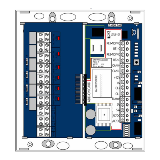
Page 6: Description Of The Board
LCU9101 Description of the board Over load 12V Out CL reader connected RE 1 Over load RE1 12V Out RE 2... -
Page 7: Indications
(OK) WDG (OK) Blue indication, normal flash approx. 2 Hz (2 flashes/sec.) Unlit – LCU9101 is starting. LED-lit – Error. A (Yellow) Flashes slowly while the control unit tries to create a connection with the ARX server. Lit when the control unit is in contact with the ARX server. -
Page 8: Settings With Dip Switches
LCU9101 to the factory settings, it also sets LCU9101 in test mode. Note! When this is done the LCU9101 will lose all settings and new information must be loaded to the LCU9101. In the test mode you can check installed readers and lock, but not the motor lock. -
Page 9: Installation
To get access to all outputs and inputs relay board DAC400RC64 must be connected. Connection of relay board is made as follows: 1. Turn off the power to LCU9101 2. Dislocate LCU9101 from the box 3. Align the contact pieces toward each other 4. -
Page 10: Jumper Links
LCU9101 Jumper links Hi-O terminering Val av NO/NC relä 1 (Ellås relä) Val av NO/NC relä 2 (LFK) 12V ut (1=+, 2=-) (12V Ut på relä 1) 12V In (1=+, 2=-) (In spänning ut på relä 1) DIP-omkopplare DIP1 Telnet ON/OFF DIP2 I läge ON initiering motorlås... -
Page 11: Terminal Blocks
ABP (Alarm bypass) RE2-C CAN-H Connection of Hi-O bus CAN- L Feeding to reader and Hi-O +12V components Directly connected motor locks and CL readers Button Exit button Door monitor switch AC/DC Feeding AC/DC LCU9101 cannot be fed with 12V! - Page 12 NO = Normal mode Blocking input (DAC-RC64 (IN3 (3&4)) The purpose of the input is to prevent access to an alarmed section. When this input is broken the LCU9101 will be blocked. LCU9101 will not accept exit button or valid cards.
-
Page 13: Initiating Motor Lock
2. Put DIP2 in position ON. 3. Turn the power on, when LCU9101 has started and LED “D” green is lit the motor lock is initiated. 4. Turn the power OFF and put DIP2 in OFF. -
Page 14: Connection Of Accessories
KP1:10 Green (C-) Balanced Door monitor switch DIP3 ON = Balanced IN on SW. Resistor of 2,2kΩ is delivered with LCU9101. These are the valid values for the input on LCU9101 (12&13) < 1,8kΩ 1,8kΩ ≤ R < 3,3kΩ ALARM 3,3kΩ... -
Page 15: Day/Night Function
LCU9101 LCU9101 must be restarted after selecting DIP3 = ON Balanced mode. Day/Night function Function selection of Day/Night input is set in ARX (IN1 4 & 6) on relay board DAC400RC64. The lock turns to DAY mode according to following selection:... -
Page 16: Poe (Power Over Ethernet)
LCU9101 PoE (Power over Ethernet) LCU9101 can be fed via PoE if the system has PoE switches or PoE injectors. The advantage with PoE is that no separate feeding has to be connected to the door, only the Ethernet connection. With PoE 12V locks are used See sketch below. -
Page 17: Configuration
LCU9101 Configuration Introduction The configuration of the control unit is made in order for the unit to make contact and communicate with the ARX ACCESS server of the system. This communication is made via the Ethernet cable through a computer network. -
Page 18: Check List
LCU9101 If you don’t know if the server name “arx” is added in the register of the DNS server or not, you can contact the network administrator and ask for help. You can also check it yourself by “pinging” the computer name “arx”. -
Page 19: Manual Configuration
When you disconnect the cable you should restart your terminal software. Unpack the zip file “drivers LCU9101 USB”, located on the support web, to a folder on the computer. Installation in Windows XP: Connect the unit to the USB port and select “Install from a list or specific location (advanced)”. -
Page 20: Terminal Software
LCU9101 Select the recommended option. When Vista shows a security warning, select “continue”, most probably the installation fails in this step. Open the device manager in the control panel. Show Other devices. Right click on “Gadget Serial” and select “Update driver”. - Page 21 LCU9101 You select one of the menu options by entering the digit that correspond to your choice and pressing [Enter]. The different options in the configuration guide are: Menu options 1. Show current configuration and status 2. Run the setup wizard – Whit this option you make the actual configuration of the control unit.
- Page 22 LCU9101 Example ”setup” After typing can for example the following information be setup shown: # setup Configuration and status LCU Serial Number: 00:06:8e:30:00:02 IP Address: automatic via DHCP Netmask: automatic via DHCP Gateway: automatic via DHCP DNS Server: automatic via DHCP...
-
Page 23: Terminal Commands
LCU9101 Terminal commands In addition to the configuration guide described above there are a number of commands that can be used at configuration and troubleshooting. A complete list over terminal commands that can be used in ARX ACCESS you find on page 20Fel! Inget bokmärkesnamn angivet.. - Page 24 LCU9101 nv del ip Command to delete the IP address for the control unit (for example an erroneous address) nv del netmask Command to delete the netting for the control unit (for example an erroneous set netting) nv init Initiates the original variables in...
- Page 25 LCU9101 Shows started programs/processes killall mux_client mux_client Disconnects the mux –d <servernamn> communication and then connects again with debug printouts activated netstat -t [-n] Shows existing connections. -n lead to an IP view. killall acp Terminates all ACP communication and restarts ACP again.
-
Page 26: Key Handling
LCU9101 Example: ”nv show” After typing (to show the variables of the control unit) nv show and pressing [Enter] the following information, for example, can be shown: # nv show factory.keys <2401 bytes> ethaddr=00:06:8e:3f:01:0a client.keys <2795 bytes> Explanation: factory.keys <2401 bytes> – factory keys (for control unit) ethaddr=00:06:8e:3f:01:0a –... -
Page 27: Technical Information
32 Mbyte SDRAM Operating system: Linux Ethernet: 10BASE-T, 100BASE-TX Configuration port: USB B-mini Card 100 000 Relay current limitation 1A (24V) Total 12V load in LCU9101, in Max 0,7A (700mA) other words 12V electric strike, reader and 12V regulated output... -
Page 28: Dimensions
LCU9101 Dimensions Diagram Reader Reader Motor lock Electric strike Läsare Läsare Motorlås Elslutbleck LCU9101 Öppnarknapp +12V...
Need help?
Do you have a question about the LCU9101 and is the answer not in the manual?
Questions and answers