Table of Contents
Advertisement
Quick Links
Incedo
Open – InControl 3270 and ToConnect 3270
™
Quick Controller Guide
Controller Unit Specifications
Power supply
17-30 V DC. A UPS solution is recommended
Internal current consumption
At 27.8 V: 96 mA Max 120 mA
PoE
PoE+ 30 W IEEE 802.3at
Power Out
12-14 V DC, max 1.6 A (independent of
power option)
Operating environment
+5 ° C to +40 ° C, RH 5 % to 95 %
IP rating
IP44
Dimensions (housing)
182.3 x 182.3 x 45.5 (W x H x D mm)
Maximum number of Device
16
converters per Controller
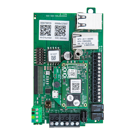
Controller Unit Overview
Hardware components such as electric strikes and readers
are connected to Controllers (InControl 3270) and Device
converters (ToConnect 3270). Settings for either controller unit
can be made on the Mode selection DIP (L), and relay jumper
pins (G). The RS-485 bus is terminated on terminal block T3 (I).
Document number: D001169528, rev 02
Publication date:
2021-08-18
Controllers are equipped with an additional controller board (D),
but the I/O connectivity is the same for both controller units.
A) RJ-45 Ethernet connector PoE+
B) RJ-45 Ethernet connector (no PoE)
C) Tamper switch
D) InControl 3270 only: Controller board
E)
InControl 3270 only: Label with MAC address (both text and
QR code) for Controller. For mounting InControl 3270 units.
F)
Terminal block T1: Analogue inputs and relay outputs
G) Relay jumper pins
H) Terminal block T2: DC IN, Hi-O, DC OUT
I)
Terminal block T3: RS-485
J)
RS-485 termination
K) Add-on card connector
L)
Mode selection DIP
M) Label with MAC address (both text and QR code) for Device
converter. For mounting converters, such as ToConnect
3270.
The MAC addresses are used to map controller units in the
Incedo™ Open web application. The Controller (InControl 3270)
has two separate MAC addresses, since it can act both as a
Controller and a Device converter.
LED Indicators
Controller and Device converter LED reference:
LED
Col
Name
On
D1
Red
Input IN1
Input is active (triggered)
D2
Red
Input IN2
Input is active (triggered)
D3
Red
Input IN3
Input is active (triggered)
D4
Yellow Relay RE1
Relay is active
D5
Yellow Relay RE2
Relay is active
D6
Red
Not used
n/a
D7
Yellow DC out over-
12 V DC output and/or
load
onboard relays draw current
beyond capacity
D8
Red
Hi-O encrypted
Hi-O bus is locked
(encrypted)
D9
Green
Hi-O unlocked
Hi-O bus is unlocked
D10 Green
RS-485 RX
Data is being received over
the RS-485 bus
D11 Red
RS-485 TX
Data is being transmitted
over the RS-485 bus
D12 Yellow Voltage
Power supply detected on
detected
DC IN terminal or PoE+ port
D13 Red
Not used
n/a
D14 Green
Network status
Device converter is communi-
cating with the Controller.
D15 Blue
Service status
Device converter is not
running the firmware
D16 Red
Controller only:
n/a
Number of
disconnected
devices
D17 Green
Controller only:
n/a
Number of
connected
devices
D18 Blue
Controller only:
n/a
Controller
status
Warning!
Ensure that the controller unit is powered off before
connecting or disconnecting any wire or cable.
Blinking
Sabotage (wire cut)
Sabotage (wire cut)
Sabotage (wire cut)
n/a
n/a
n/a
n/a
n/a
n/a
n/a
n/a
n/a
n/a
IP address received
Device converter is running
the firmware
Blinking to indicate number
of disconnected devices
(Device converter or Well-
Com units). One blink per
disconnected device, then
a pause for 3-4 seconds
(repeated).
Blinking to indicate number
of connected devices
(Device converter or
WellCom units). One blink
per connected device, then
a pause for 3-4 seconds
(repeated).
Slow blinking: Controller
is working, connected
to cloud. Fast blinking:
Controller is not connected
to cloud.
1
Advertisement
Table of Contents

Related Manuals for Assa Abloy Incedo InControl 3270


Summary of Contents for Assa Abloy Incedo InControl 3270
- Page 1 Incedo Open – InControl 3270 and ToConnect 3270 ™ Quick Controller Guide Controller Unit Specifications LED Indicators Controllers are equipped with an additional controller board (D), but the I/O connectivity is the same for both controller units. Controller and Device converter LED reference: Power supply 17-30 V DC.
- Page 2 The LEDs on the PCB are turned off when the lid is Cables can either be run from a hole in the wall or from the A new system is created by ASSA ABLOY Opening Solutions closed properly, with the tamper spring in correct sides.
- Page 3 Incedo Open – InControl 3270 and ToConnect 3270 ™ Quick Controller Guide Connecting 12 V Electric Strike Connecting 24 V Electric Strike Adding Hi-O Devices +12 V Mode selection DIP (A), Hi-O device or bus (B). Locate terminal block T2. Connect the Hi-O bus device to the controller unit.
- Page 4 Incedo Open – InControl 3270 and ToConnect 3270 ™ Quick Controller Guide Ensure that the remaining Hi-O devices are connected to the For more information, download the latest versions of: DIP4 = ON: Failsafe for electric strikes. bus. Unpowered strikes are open. DIP4 = OFF: Failsecure for electric strikes.
Need help?
Do you have a question about the Incedo InControl 3270 and is the answer not in the manual?
Questions and answers