
Related Manuals for Assa Abloy EffEff 1338-15


Summary of Contents for Assa Abloy EffEff 1338-15
- Page 1 Fluchttür-Steuerterminal 1338-/1340-14/-15/-20/-21 Installations- und Montageanleitung ASSA ABLOY, the global leader in D00135 door opening solutions...
-
Page 3: Table Of Contents
Inhalt FUNKTION UND BEDIENUNG ..............5 Hinweise ........................6 Allgemeine Beschreibung ..................6 1.2.1 Modellbeschreibung ..........................7 Funktionsbeschreibung ....................7 1.3.1 Funktion beim Einschalten oder Netzwiederkehr ..............7 1.3.2 Kurzzeitfreigabe............................. 8 1.3.3 Dauerentriegelung..........................9 1.3.4 Verriegelung............................9 Alarm........................10 1.4.1 Gefahrenalarm............................10 1.4.2 Anschluss und Alarm durch eine Brandmeldeanlage (Klemme 13/14) ......11 1.4.3 Sabotagealarm .............................11 1.4.4... - Page 4 Technische Daten und Anschlussplan für 1340 Version 12V ......28 2.7.1 Elektrische Daten..........................28 2.7.2 Technische Daten..........................28 2.7.3 Anschließbare Verriegelungselemente..................28 2.7.4 Anschlussplan Fluchttür-Steuergerät 1340-20 (12V) .............29 Technische Daten und Anschlussplan für 1340 Version 24 V......30 2.8.1 Elektrische Daten..........................30 2.8.2 Technische Daten..........................30 2.8.3 Anschließbare Verriegelungselemente..................30 2.8.4...
-
Page 5: Funktion Und Bedienung
Funktion und Bedienung D00135 Seite 5... -
Page 6: Hinweise
1.1 Hinweise Für die Installation und den Betrieb von elektrischen Verriegelungen von Türen in Rettungswegen sind baurechtliche Bestimmungen zu beachten! Die Übereinstimmung der Geräte mit der “Richtlinie über elektronische Verriegelungs- systeme von Türen in Rettungswegen (EltVTR)” (Bauregelliste A Teil 1, lfd. Nr 6.19) ist geprüft vom TÜV Rheinland, Köln. -
Page 7: Modellbeschreibung
1.2.1 Modellbeschreibung 1.2.1.1 Fluchttür-Steuerterminal Modelle 1338-14/-15/-20/-21 Diese Steuerterminals besitzen zusätzlich zu der gesamten Steuerelektronik ein integriertes Netzteil, das sowohl die Elektronik des Steuerterminals als auch die Verriegelungselemente mit der nötigen Spannung versorgt. Die Steuerterminals können sowohl als Stand-Alone-Gerät als auch als Busteilnehmer betrieben werden. 1.2.1.2 Fluchttür-Steuerterminal Modelle 1340-14/-15/-20/-21 Diese Steuerterminals haben den gleichen Funktionsumfang wie die Modelle 1338…, besitzen jedoch kein internes Netzteil. -
Page 8: Kurzzeitfreigabe
1.3.2 Kurzzeitfreigabe Das Steuerterminal bietet die Möglichkeit, die verriegelte Tür mit der Funktion „Kurzzeitfreigabe“ für die an S1 eingestellte Zeit, zu entriegeln. Dazu muss der interne Schlüsseltaster in Richtung „Verriegeln“ betätigt oder das Steuerterminal über die Klemmen 11/12 bzw. 17/20 angesteuert werden. Angezeigt wird der Zustand „Kurzzeitfreigabe“... -
Page 9: Dauerentriegelung
1.3.3 Dauerentriegelung Das Steuerterminal bietet die Möglichkeit, die verriegelte Tür über die Funktion „Dauerentriegelung“ zu entriegeln. Dies kann auf zwei Arten erfolgen. Bei der ersten Möglichkeit entriegelt die Tür sofort, wenn der interne Schlüsseltaster in Richtung “Entriegeln” betätigt wird (abhängig von JP2) oder eine Ansteuerung durch einen externen Kontakt an den Klemmen 9/10 erfolgt. -
Page 10: Alarm
1.4 Alarm Ein Alarm wird ausgelöst, sobald eine der nachfolgend aufgeführten Bedingungen gegeben ist. Dabei unterscheidet man drei Arten von Alarmen. • Den Gefahrenalarm • Den Sabotagealarm • Den Alarm in Verbindung mit der Überwachung der Türöffnungszeit Quittieren: Wurde ein Alarm ausgelöst, kann dieser nur in zwei Schritten zurückgesetzt werden. Im ersten Schritt muss zunächst der Alarm quittiert werden. -
Page 11: Anschluss Und Alarm Durch Eine Brandmeldeanlage (Klemme 13/14)
1.4.2 Anschluss und Alarm durch eine Brandmeldeanlage (Klemme 13/14) Am Fluchttürsteuerterminal kann zusätzlich der Auslösekontakt einer Brandmeldeanlage (Ruhestromschleife) angeschlossen werden. Durch das Auslösen der Brandmeldeanlage wird am Steuerterminal Alarm ausgelöst und die Tür sofort entriegelt. Wichtiger Hinweis! Wird am Steuerterminal kein Brandmeldekontakt angeschlossen, so sind die Anschlussklemmen 13/14 unbedingt mit einer Drahtbrücke zu verbinden. -
Page 12: Überwachung Der Türöffnungszeit
1.4.6 Überwachung der Türöffnungszeit Die Tür wird auf die maximal zulässige Öffnungszeit hin überwacht. Kann die Tür nach einer Kurzzeitfreigabe nicht verriegelt werden, weil sie nicht geschlossen ist, erfolgt nach der mit S1 vorgewählten Freigabezeit der Voralarm. Nach Ablauf der mit S2 vorgewählten Voralarmzeit, erfolgt der Alarm (Im Busbetrieb müssen die Zeiten am Bus-Steuerungstableau eingestellt werden). -
Page 13: Übersicht Über Bedien- Und Anzeigeelemente
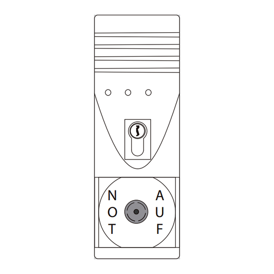
1.5 Übersicht über Bedien- und Anzeigeelemente Leuchtdioden-Türstatusanzeige = Fluchttür verriegelt rot / gelb = Fluchttür verriegelt. Tür war zu lange offen und wurde wieder geschlossen / die Tür wurde aufgebrochen oder Sabotage. grün = Fluchttür entriegelt grün blinkend (9:1)* = Kurzzeitentriegelung grün blinkend (1:1)* = quittierter Alarm, Alarmgrund steht noch an grün / gelb... -
Page 14: Ermittlung Einer Alarmbedingung
1.6 Ermittlung einer Alarmbedingung Am Steuerterminal kann festgestellt werden, wodurch ein Alarm ausgelöst wurde, bzw. welche Alarmbedingung noch ansteht. Hinweis: Die Alarmbedingungen sind nur abfragbar, solange der Alarm noch ansteht und die grüne Leuchtdiode im Verhältnis 1:1 blinkt. Dazu muss folgendermaßen vorgegangen werden. Zuerst muss der Alarm quittiert werden. Anschließend den internen Schlüsseltaster zuerst nach links drehen, halten, und die Anzeige im Steuerterminal beachten. -
Page 15: Einstellmöglichkeiten Am Fluchttür-Steuerterminal
1.7 Einstellmöglichkeiten am Fluchttür-Steuerterminal 1.7.1 Steckbrücke JP-1 JP-1 gesteckt = Voralarm “Ein” (Auslieferungszustand). Dies bedeutet, dass vor einem möglichen Alarm nach Ablauf der Lautstärke ausgelöst wird. Der potenzialfreie Alarmkontakt sowie die optische Anzeige werden vom Voralarm nicht beeinflusst. JP-1 offen = Voralarm “Aus”. Dies bedeutet, dass ein akustischer Voralarm unterdrückt und nach Ablauf der an S2 eingestellten Zeit der Alarm ausgelöst wird. - Page 16 1.7.8 Vorwahlschalter S1: Freigabezeit Zeitbereich: 11 bis 176 Sekunden (11-Sekunden-Raster) bei Kurzzeitfreigabe: Wird die Kurzzeitfreigabe gestartet, erfolgt die Entriegelung der Tür für die Zeit, die an S1 eingestellt ist. Nach deren Ablauf wird die geschlossene Tür wieder verriegelt. Ist die Tür nach dem Öffnen nicht geschlossen worden, wird nach Ablauf der Kurzzeitfreigabezeit der Voralarm und nach dessen Ablauf, Alarm ausgelöst (abhängig von Steckbrücke JP-1 und Vorwahlschalter S 4.1).
- Page 17 1.7.11 Vorwahlschalter S4: Beleuchtung NOT-AUF-Schalter Die Beleuchtung des NOT-AUF-Schalters können Sie am DIP-Schalter S4 auf der Beleuchtungsplatine wie folgt einstellen: OFF ON OFF ON Beleuchtung: Beleuchtung: ist ausgeschaltet ist dunkel bei entriegelt leuchtet rot bei verriegelt Beleuchtung: Beleuchtung: leuchtet grün bei entriegelt leuchtet grün bei entriegelt ist dunkel bei verriegelt leuchtet rot bei verriegelt...
- Page 18 Seite 18 D00135...
-
Page 19: Montage Und Installation
Montage und Installation D00135 Seite 19... -
Page 20: Hinweise
2.1 Hinweise! Gefahr durch elektrischen Strom! Bei Berührung von stromführenden Teilen kann es zu einer lebensgefährlichen Körperdurchströmung kommen. Vor Installation, Wartungsarbeiten und Öffnen des Gehäuses Spannungsfrei schalten Vor unbeabsichtigtem und selbsttätigen Einschalten sichern Unfallverhütungsvorschriften beachten Für die Installation und den Betrieb von elektrischen Verriegelungen von Türen in Rettungswegen sind baurechtliche Bestimmungen zu beachten! Die Geräte entsprechen den in der Europäischen Union geltenden Richtlinien bezüglich elektromagnetischer Verträglichkeit (EMV). -
Page 21: Hinweise Zur Montage
2.2 Hinweise zur Montage Das Fluchttürterminal ist in unmittelbarer Nähe der Fluchttür zu montieren. Das Fluchttür- Steuerterminal ist für die Wandmontage vorgesehen. Um baulichen Anforderungen gerecht zu werden, steht eine Aufputz-(AP) und eine Unterputz-(UP) Ausführung zur Verfügung. Der UP-Ausführungen liegt zusätzlich eine Einputzdose aus verzinktem Stahlblech und ein Zubehörbeutel mit Montagematerial bei. -
Page 22: Leitungsauswahl
2.3 Leitungsauswahl Bei der Installation muss beachtet werden, dass die Steuerleitungen maximal 300 m und Leitungen zum Verriegelungsteil maximal 100 m lang sein dürfen. Des weiteren muss der Leitungsquerschnitt so gewählt werden, dass die Spannung am Verriegelungsteil bei Vollast und unter Berücksichtigung aller weiteren Verluste, wie z.B. des Spannungabfalls auf der Zuleitung, maximal 10% unter der angegebenen Betriebsnennspannung des Verriegelungsteils liegt. -
Page 23: Auswechseln Des Profilhalbzylinders
2.4.2 Auswechseln des Profilhalbzylinders Sollte es nötig sein, den eingebauten Profilhalbzylinder gegen ein anderes Modell auszutauschen, z.B. wenn das Fluchttür-Steuergerät in ein vorhandenes Schließsystem integriert werden soll, so muss zuerst der eingebaute Profilhalbzylinder demontiert und anschließend der Austauschzylinder montiert werden. Bei den notwendigen Arbeiten ist auf besondere Sorgfalt zu achten, um Beschädigungen am Steuergerät zu vermeiden. -
Page 24: Busbetrieb - Modelle 1338-20/-21 Und Modelle 1340-20/-21
2.5 Busbetrieb – Modelle 1338-20/-21 und Modelle 1340-20/-21 Wird das Fluchttür-Steuerterminal in der Betriebsart 2 am TS-Bus in Verbindung mit einem Bus- Steuerungstableau 925 betrieben, erfolgt die Steuerung und Überwachung der Fluchttür nach wie vor durch das Steuerterminal. Der gesamte bereits beschriebene Funktionsumfang des Steuerterminals sowie der Ablauf der einzelnen Funktionen stehen im Busbetrieb nahezu unverändert zur Verfügung. - Page 25 Die gleichzeitige Drehschalterstellung S3 --> 0 und S2 --> 0 ist nicht zulässig Beispiel: Es soll die Teilnehmeradresse 58 am Fluchttürterminal eingestellt werden. Der Drehschalter S3 für den Adressbereich muss dazu in Stellung 3 gebracht werden. Diese Einstellung entspricht dem Adressbereich 48-63. Von der Adresse 48 ausgehend, muss nun die Differenz zu der gewünschten Adresse 58, in diesem Fall 10, mit dem Drehschalter S2 für die Einzeladressen eingestellt werden.
-
Page 26: Technische Daten Und Anschlussplan Für 1338
Technische Daten und Anschlusspläne 2.6 Technische Daten und Anschlussplan für 1338 2.6.1 Elektrische Daten 2.6.1.1 Primär Betriebsnennspannung 230 VAC +10% / -15% / 50-60 Hz Nennstromaufnahme Max. 0,4 A 2 A träge (Kleinstsicherung Serie 382; Sicherung F1 (Platine Netzteil) Wickmann, Typ TR .5 Das Gerät muss durch eine leicht zugängliche Trennvorrichtung vomVersorgungsstromkreis getrennt werden können 2.6.1.2 Sekundär... -
Page 27: Anschlussplan Fluchttür-Steuergerät 1338-20
2.6.3 Anschlussplan Fluchttür-Steuergerät 1338-20 Modelle 1338-20/-21, 1340-20/-21 D00135 Seite 27... -
Page 28: Technische Daten Und Anschlussplan Für 1340 Version 12V
2.7 Technische Daten und Anschlussplan für 1340 Version 12V 2.7.1 Elektrische Daten Nennbetriebsspannung 12 VDC 12 VDC ±10% stabilisierte Gleichspannung Betriebsspannungsbereich (Restwelligkeit max. 1 Vss) Das Netzteil für die Spannungsversorgung des Geräts muss der aktuellen DIN EN 60950 entsprechen! Eigenstromaufnahme max. -
Page 29: Anschlussplan Fluchttür-Steuergerät 1340-20 (12V)
2.7.4 Anschlussplan Fluchttür-Steuergerät 1340-20 (12V) Modelle 1338-20/-21, 1340-20/-21 D00135 Seite 29... -
Page 30: Technische Daten Und Anschlussplan Für 1340 Version 24 V
2.8 Technische Daten und Anschlussplan für 1340 Version 24 V 2.8.1 Elektrische Daten Nennbetriebsspannung 24 VDC 24 VDC ±10% stabilisierte Gleichspannung Betriebsspannungsbereich (Restwelligkeit max. 1 Vss) Das Netzteil für die Spannungsversorgung des Geräts muss der aktuellen DIN EN 60950 entsprechen! Eigenstromaufnahme max. -
Page 31: Anschlussplan Fluchttür-Steuergerät 1340-20/21 (24V)
2.8.4 Anschlussplan Fluchttür-Steuergerät 1340-20/21 (24V) Modelle 1338-20/-21, 1340-20/-21 D00135 Seite 31... - Page 32 Seite 32 D00135...
-
Page 33: Inbetriebnahme, Wartung, Wiederkehrende Prüfung
Inbetriebnahme, Wartung, wiederkehrende Prüfung Einbau und Betrieb von elektrischen Verriegelungen von Türen in Rettungswegen unterliegen bauaufsichtlichen Regelungen, deren Einhaltung sowohl von Seiten des Installateurs als auch seitens des Betreibers sicherzustellen ist. 3.1 Inbetriebnahme und wiederkehrende Prüfung Vor der ersten Inbetriebnahme eines elektrischen Fluchttürverriegelungssystems muss der ordnungsgemäße Einbau aller Elemente und deren elektrischer Anschluss überprüft werden. -
Page 34: Checkliste Zur Prüfung Vor Erstinbetriebnahme
Checkliste zur Prüfung vor Erstinbetriebnahme 4.1 Komponenten • Alle Komponenten entsprechen der EltVTR? - eingebautes Verriegelungselement .................O - Steuerung ........................O - Bedienelement......................O • Einbau- und Betriebsanleitung • Formular für Prüfung des Fluchttürverriegelungssystems vor Erstinbetriebnahme ist vorhanden ....................O • Bei externer Stromversorgung des Verriegelungssystems oder von Teilen desselben: Entspricht die Energieversorgung EN 60 950 (CE-Zeichen vorhanden)? ...... - Page 35 Wenn eine Gefahrenmeldeanlage (z.B. Brandmeldeanlage) aufgeschaltet ist: Alarm zurücksetzen Verriegelungssystem aktivieren! Prüfen, ob rote Anzeige am Bedienelement leuchtet!. Prüfen (manuell), ob Tür sicher verriegelt ist! Ruhestromschleife der Gefahrenmeldeanlage öffnen! • Die Tür wird unverzögert freigegeben..................... O • Die Tür kann ohne erheblichen Kraftaufwand geöffnet werden ..........O •...
- Page 36 • Für Ihre Notizen Seite 36 D00135...
- Page 37 Emergency Exit Control Terminal 1338-/1340-14/-15/-20/-21 Installation- and Mounting Instruction ASSA ABLOY, the global leader in D00135 door opening solutions...
- Page 39 Content FUNCTIONAL CHARACTERISTICS AND OPERATION......41 Notes ..........................42 General description ......................42 1.2.1 Model description ..........................43 Functional characteristics ...................43 1.3.1 Functional characteristics when switching on or on return of the power supply... 43 1.3.2 Temporary release..........................44 1.3.3 Permanent unlocking..........................45 1.3.4 Locking ...............................
- Page 40 Specifications and terminal diagram for 1340-20/21 Version 12V ....64 2.7.1 Electrical data............................64 2.7.2 Specifications............................64 2.7.3 Possible connecting locking elements.................... 64 2.7.4 Terminal diagram for 1340-20 (12V)....................65 Specifications and terminal diagram for 1340-20/21 Version 24 V ....66 2.8.1 Electrical data............................
-
Page 41: Functional Characteristics And Operation
Functional characteristics and operation D00135 Seite 41... -
Page 42: Notes
1.1 Notes The relevant statutory building regulations must be observed when installing and operating electrical locks in escape routes. Agreement of the units with the "Directive on locking systems for doors in escape routes (EltVTR 12/97)" (Building register A part 1, no. 6.19) has been tested by TÜV Rheinland, Cologne 1.2 General description The emergency exit control terminal type 1338/1340 is designed for the control and monitoring... -
Page 43: Model Description
1.2.1 Model description 1.2.1.1 Emergency exit control terminal type 1338-14/-15/-20/-21 Alongside the entire electronic control circuit, these control terminals are fitted with an additional power supply unit which supplies both the electronic circuitry in the control terminal and also the locking elements with the required voltage. The control terminals can either be operated as stand-alone unit or as bus user. -
Page 44: Temporary Release
1.3.2 Temporary release The control terminal permits the locked door to be unlocked for the time period set at S1 using the "Temporary release" function. For this to be possible, the internal key-operated switch must be actuated in the "locking" direction or the control terminal actuated via terminals 11/12 or 17/20. -
Page 45: Permanent Unlocking
1.3.3 Permanent unlocking The control terminal offers the possibility to unlock a locked door using the "Permanent unlocking" function. This can be carried out in two ways. With the first possibility, the door unlocks immediately when the internal key-operated switch is actuated in the "unlocking"... -
Page 46: Alarm
1.4 Alarm An alarm is triggered as soon as one of the conditions listed below exists. A difference is drawn here between three different types of alarm • the danger alarm • the sabotage alarm • the door monitoring time alarm Acknowledgement: If an alarm has been tripped, this can be reset in two steps. -
Page 47: Connection And Alarm By Means Of A Fire Alarm System (Terminal 13/14)
1.4.2 Connection and alarm by means of a fire alarm system (terminal 13/14) Connection and alarm by means of a fire alarm system (terminal 13/14). At the effeff emergency exit control terminal, it is additionally possible to connect the tripping contact of a fire alarm system (fail unlocked loop). -
Page 48: Monitoring The Door Opening Time
1.4.6 Monitoring the door opening time The door is monitored for the maximum admissible opening time. If the door cannot be locked after a temporary release because it is not closed, after the release time preselected with S1 a pre-alarm status is initiated. After expiry of the pre-alarm time selected with S2, the alarm proper is initiated (in the bus mode, the times must be set at the bus control panel). -
Page 49: Overview Of Operating And Display Elements
1.5 Overview of operating and display elements LED door status display = Emergency exit is locked red / yellow = Emergency exit is locked. Door was open for too long and has been closed again / the door has been broken open or an attempted sabotage has taken place green = Emergency exit unlocked... -
Page 50: Determination Of An Alarm Condition
1.6 Determination of an alarm condition At the control terminal, it is possible to determine what has tripped an alarm or which alarm condition is still active. Note: The alarm conditions can only be investigated as long as the alarm is still active and the green LED is flashing at a ratio of 1:1. -
Page 51: Setting Possibilities At The Emergency Exit Control Terminal
1.7 Setting possibilities at the emergency exit control terminal 1.7.1 Plug-in jumper JP-1 JP-1 in place = Pre-alarm "On" (As-delivered status). This means that before a possible alarm after expiry of the door release time an acoustic pre-alarm with reduced volume is tripped. The floating alarm contact and the optical display are not influenced by the pre-alarm. - Page 52 1.7.8 Preselection switch S1: Release time Release time range: 11 to 176 seconds (11-second-increments) With temporary release: If the temporary release is started, the door is unlocked for the time set at S1. After expiry of this time, the closed door is locked again. If the door is not closed after opening, after expiry of the temporary release time, the pre-alarm is initiated and after its expiry, the alarm proper (dependent on plug-in jumper JP-1 and preselection switch S 4.1).
- Page 53 1.7.11 Preselection switch S4: Illumination Emergency Exit Button The illumination of the Emergency Exit Button could be set at the DIP-switch S4 on the illumination-panel as followed: OFF ON OFF ON illumination: illumination: is switched off is dark if unlocked red if locked illumination: illumination:...
- Page 54 Seite 54 D00135...
-
Page 55: Mounting And Installation
Mounting and Installation D00135 Seite 55... -
Page 56: Notes
2.1 Notes! Danger Electrical Hazard! Touching current carrying parts will cause an electric shock. Before Installation, maintenance and open the housing switch to tension-free protect from unintended and self-acting activation notice accident prevention regulations The relevant statutory building regulations must be observed when installing andoperating electrical locks in escape routes! The devices are in compliance with the directives applicable in the European Union relating to electromagnetic compatibility (EMC). -
Page 57: Mounting Instructions
2.2 Mounting instructions The emergency exit terminal must be mounted in the direct vicinity of the emergency exit. The emergency exit control terminal is intended for wall mounting. In order to address structural requirements, a surface-mounted and a flush mounted version are available. The flush mounted versions come with an additional flush mounted socket in galvanized sheet steel and an accessory bag containing mounting materials. -
Page 58: Choosing The Right Cables
2.3 Choosing the right cables When installing, remember that the control cables may be no longer than 300 m and lines to the locking part no longer than 100 m long. In addition, the cable cross-section must be selected so that the voltage at the locking element under load, and taking into consideration all other possible losses such as the voltage drop at the supply line, is no more than 10% below the specified rated operating voltage of the locking element. -
Page 59: Exchanging The Multi-Led Or The Profile Half-Cylinder
2.4.2 Exchanging the multi-LED or the profile half-cylinder Should it be necessary to exchange the installed profile half-cylinder for a different model, e.g. if you wish to integrate the emergency exit control unit into an existing locking system, initially the integrated profile half-cylinder must be dismantled and subsequently the exchange cylinder mounted. -
Page 60: Bus Mode - Models 1338-20/-21 And Models 1340-20/-21
2.5 Bus mode – models 1338-20/-21 and models 1340-20/-21 If the emergency exit control terminal is to be used in operating mode 2 at the TS-Bus in conjunction with a bus control panel 925, control and monitoring of the emergency exit continues to be performed by the control terminal. - Page 61 Simultaneous rotary switch setting S3 --> 0 and S2 --> 0 is not admissible Example: You wish to set emergency exit address 58 at the emergency exit terminal. For this, the rotary switch S3 for the address must be moved to position 3. This setting corresponds to the address range 48-63.
-
Page 62: Specifications And Terminal Diagrams For 1338
Specifications and terminal diagrams 2.6 Specifications and terminal diagrams for 1338 2.6.1 Electrical data 2.6.1.1 Primary Supply voltage 230 VAC +10% / -15% / 50-60 Hz Current consumption Max. 0,4 A 2 A slow-blowing (sub-miniature series 382; Fuse F1 (Power supply panel) Wickmann, type TR .5) protected version The device must be configured to permit isolation from the supply circuit by means of an easily accessible isolating device. -
Page 63: Terminal Diagram For 1338-20
2.6.3 Terminal diagram for 1338-20 Locked Potential free Relais Unlocked max. 24 V/1A TS-BUS Locked Unlocked Alarm Lock Unlock – Central release Relais “Alarm” Potential free, max 24 V/1A External Emergency Release e. g. Fire Alarm System Temporary Release Permanent Release (Timer, Switch) D00135 Seite 63... -
Page 64: Specifications And Terminal Diagram For 1340-20/21 Version 12V
2.7 Specifications and terminal diagram for 1340-20/21 Version 12V 2.7.1 Electrical data Rated operating voltage 12 VDC 12 VDC ±10% stabilized direct voltage Operating voltage range (residual ripple max. 1 Vss) The power supply unit for the voltage supply of the device must correspond to DIN EN 60950! Intrinsic current consumption max. -
Page 65: Terminal Diagram For 1340-20 (12V)
2.7.4 Terminal diagram for 1340-20 (12V) Locked Potential free Relais Unlocked max. 24 V/1A Models 1338-20/-21, 1340-20/-21 TS-BUS Locked Unlocked Alarm Lock Unlock – Central release Relais “Alarm” Potential free, max 24 V/1A External Emergency Release e. g. Fire Alarm System Temporary Release Permanent Release (Timer, Switch) -
Page 66: Specifications And Terminal Diagram For 1340-20/21 Version 24 V
2.8 Specifications and terminal diagram for 1340-20/21 Version 24 V 2.8.1 Electrical data Rated operating voltage 24 VDC 24 VDC ±10% stabilized direct voltage Operating voltage range (residual ripple max. 1 Vss) The power supply unit for the voltage supply of the device must correspond to DIN EN 60950! Intrinsic current consumption max. -
Page 67: Terminal Diagram For 1340-20/21 (24V)
2.8.4 Terminal diagram for 1340-20/21 (24V) Locked Potential free Relais Unlocked max. 24 V/1A Models 1338-20/-21, 1340-20/-21 TS-BUS TS-BUS Locked Unlocked Alarm Lock Unlock – Central release Relais “Alarm” Potential free, max 24 V/1A External Emergency Release e. g. Fire Alarm System Temporary Release Permanent Release (Timer, Switch) - Page 68 Seite 68 D00135...
-
Page 69: Commissioning, Maintenance, Recurring Tests
Commissioning, maintenance, recurring tests The installation and operation of electrical locking systems for doors in escape routes are subject to building supervisory regulations. Adherence to these regulations must be ensured by both the installer and the operator. 3.1 Commissioning and recurring tests Prior to initial commissioning of an electrical emergency exit locking system, correct installation of all elements and their electrical connection must be checked. -
Page 70: Checklist For Testing Prior To Initial Commissioning
Checklist for testing prior to initial commissioning 4.1 Components • All components comply with the EltVTR? - Integrated locking element..................O - Control system......................O - Operating element ....................O • Installation and operating instructions available................O • Form sheet for testingprior to initial commissioning is available..........O •... - Page 71 If a danger signally system (e.g. fire alarm system)is connected: Reset the alarm! Activate the locking sytem! Check whether the red display is alight at the operating element! Check (manually) whether the door is securely locked! Open the closed current loop of the danger signally system! •...
- Page 72 • For your notices: Seite 72 D00135...
- Page 73 • For your notices D00135 Seite 73...
- Page 74 • For your notices Seite 74 D00135...
- Page 76 ASSA ABLOY ist der weltweit führende Hersteller ZEISS IKON AG, ist in Deutschland die erfolgreichste und Lieferant von Schließlösungen und Sicherheits- Marke von ASSA ABLOY für Schließ- und Sicherheits- systemen, die den hohen Ansprüchen der Kunden technik. Produkte und Lösungen der Marke IKON...
Need help?
Do you have a question about the EffEff 1338-15 and is the answer not in the manual?
Questions and answers