
Related Manuals for Assa Abloy TRAKA UD0011


Summary of Contents for Assa Abloy TRAKA UD0011
- Page 1 TRAKA TOUCH USER GUIDE UD0011 01/05/20 VERSION 9.7 This Document is the subject of copyright and must not be copied or otherwise reproduced either in whole or in part without the express written permission of TRAKA.
- Page 2 VERSION HISTORY Approved Version Date Description of Changes 30/06/11 Initial version of document Changed the layout of the document and added the network 29/07/11 section. Also made various updates to most sections. 08/07/14 Made general updates to various sections. 04/08/14 Changed the Traka Touch PCB section represent iMX28 hardware Added following sections –...
- Page 3 Screenshots updated with Traka Touch v2.0 Language menu changes. Added information for RRMS, RTUS, FIFO & Access 13/07/18 WT/RC Schedules to Feature Options section. TT to TW Sync ‘The Ladder’ updated for v2.0.0 of TW. Added ‘Enforce TLS 1.2’ details to section 11.7.1 Section 5.4, USB information added and referenced within 13/08/18...
-
Page 4: Table Of Contents
CONTENTS Contents ................................ 4 Introducing Traka ........................... 11 Traka Contact Details ..........................12 Product Details ............................13 Electrical Rating ..........................13 Environmental Rating ........................13 Compliance Level ........................... 13 3.3.1 USA and Canada ........................13 3.3.2 Europe ............................13 What and Whom is this Guide For? ......................14 Traka Cabinet and item Diagrams ...................... - Page 5 Users ..............................27 Creating The First Admin User ......................27 Adding more Users ......................... 33 Editing Users ..........................37 Deleting users..........................38 Supporting a Large Number of Users ....................39 User Enrolment ID .......................... 40 Item Setup ............................43 Initial Setup ..........................43 9.1.1 DeAllocating an iFob ........................
- Page 6 12.5.1 Exporting Users ........................71 12.5.2 Importing Users ........................73 12.6 General Options ..........................77 12.7 Network Administration ........................80 12.7.1 Enforce TLS 1.2 ........................81 12.8 Changing Certificates in the Traka Touch ‘Root Store’ ................. 81 12.9 Add the New CA Certificate into the Traka Touch ‘Root Store’ (V2.3.0 & Later)........85 12.9.1 Add the new CA Certificate into the Traka Touch ‘Root Store’...
- Page 7 13.2.3 Traka Touch Application ......................117 13.3 Access Methods..........................118 13.4 Reader Disconnection / Reconnection ..................... 118 13.5 How to Enrol a User ........................119 13.5.1 Manual Enrolment by Admin ....................119 13.5.2 Enrolment ID ........................121 13.6 How to Access The System ......................122 13.7 Removing a Fingerprint Template ....................
- Page 8 17.12 Access Schedules ........................136 17.13 Real-Time Update Service ......................136 17.14 TrakaWEB System Viewer Grid ....................137 17.15 TrakaWEB Admin Job Scheduler ....................142 17.15.1 Ribbon Toolbar Buttons ......................143 General Maintenance ......................... 144 18.1 Powering On/Off the System ......................144 18.2 Manually Opening the Door ......................
- Page 9 V9.7 01/05/20 UD0011 Page 9 of 177 This Document is uncontrolled when printed unless over stamped “CONTROLLED DOCUMENT"...
- Page 10 GDPR COMPLIANCE INFO RMATION Traka supplies Key Cabinets and intelligent Locker systems. These products keep keys & assets safe from unauthorised access, and allow only authorised users to remove and return the keys/assets they are entitled to. Traka systems give full accountability of who has (or had) which keys/assets and at what time and date.
-
Page 11: Introducing Traka
In April 2012 Traka was acquired by ASSA ABLOY, the world leader in door locking solutions. -
Page 12: Traka Contact Details
TRAKA CONTACT DETAIL S Switchboard Tel: +44 (0)1234 712345 Account Manager Account Manager Name: Direct Contact Tel: Contact Email: Account Manager 2 (if applicable) Account Manager Name 2: Direct Contact Tel 2: Contact Email 2: Technical Support / Help Desk Help Desk Direct Tel: UK Telephone: 0333 355 3641 International Telephone: +(0)44 333 355 3641... -
Page 13: Product Details
PRODUCT DETAILS NOTE: Please ensure that the correct installation procedures have been utilised and the product is safely secured. ELECTRICAL RATING Power supply: Input: 100-240V AC 50/60Hz 35W Max Battery backup: V-Series – DC12v 7Ah M-Series - DC12v 7Ah ... -
Page 14: What And Whom Is This Guide For
WHAT AND WHO M IS THIS GUIDE FOR? This User Guide has been prepared to assist you (the end user) with the operating basics of the Traka Touch System. Please keep this guide handy for those times when you need to remember how to Add a user, Replace an iFob... -
Page 15: Traka Cabinet And Item Diagrams
TRAKA CABINET AND ITEM DIAGRAMS CABINET TYPES V9.7 01/05/20 UD0011 Page 15 of 177 This Document is uncontrolled when printed unless over stamped “CONTROLLED DOCUMENT"... -
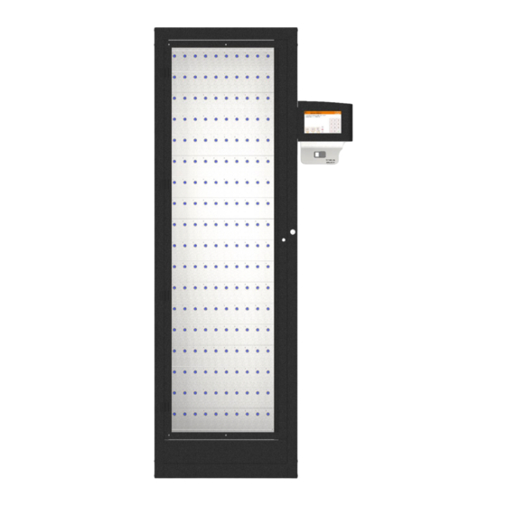
Page 16: Cabinet Diagram
CABINET DIAGRAM 5.2.1 CABINET DIAGRAM KEY Cabinet Cam Lock This cam lock is a manual override for the cabinet door. 2 keys are supplied with your Traka system. We ask that you do not keep these keys in the Traka cabinet. In case of system failure, you will be required to access those keys and use this cam lock as a manual override to open the cabinet door. -
Page 17: Ifob (Intelligent Fob) & Key Bunch Diagram
IFOB (INTELLIGENT FOB) & KEY BUNCH DIAGRAM 5.3.1 IFOB DIAGRAM KEY iFob The item is at the heart of any Traka Key Management system. It is a bullet shaped device made from nickel plated brass. It contains a microchip with a unique identification number allowing the Traka system to identify the key(s) attached. -
Page 18: Usb Memory Sticks
USB MEMORY STICKS NOTE: USB memory sticks should be formatted to FAT32 and not NTFS when used in a Traka Touch system, as NTFS is not supported by the Windows CE operating system used. NOTE: Files should be located on the root of the USB memory stick and not in sub folders. This is to ensure that the Traka Touch software is able to locate them. -
Page 19: Overview
OVERVIEW The Traka Touch system uses touch screen technology for an easy, user-friendly interface. The Traka Touch does not require the use of a stylus or any other navigation device, to use the system simply select the desired buttons with your finger. -
Page 20: Top Bar Icons
6.2.3 TOP BAR ICONS Certain icons will be displayed in the top bar of the Touch system to indicate the current status of the system. Mains Power Connected – This icon will be present as long as the system is connected to mains power. USB Memory Stick Inserted –... -
Page 21: Types Of Identification
TYPES OF IDENTIFICATION The way in which you access the system depends upon the type of identification device fitted, e.g. biometrics reader, card reader or simply a Keypad ID. In addition to a user’s primary means of identification, a user may also be given a Secondary PIN providing extra security. -
Page 22: Keypad Id Only Access
7.1.2 KEYPAD ID ONLY ACCESS Touch the screen to bring the system out of idle mode. Enter your Keypad ID and press (enter). Verify your user name on the touch screen. 7.1.3 KEYPAD AND PIN ACCESS Touch the screen to bring the system out of idle mode. Enter your Keypad ID and press Enter your PIN and press Verify your user name on the touch screen. -
Page 23: Fingerprint Access
7.1.6 FINGERPRINT ACCESS Touch the screen to bring the system out of idle mode. The reader will illuminate red. Place your finger on the reader. Verify your user name on the touch screen. 7.1.7 FINGERPRINT AND PIN ACCESS Touch the screen to bring the system out of idle mode. &... -
Page 24: Selecting An Option On Login
7.1.8 SELECTING AN OPTION ON LOGIN Below are examples of what users with different access permissions will see when they log in. By default each system is set up to work in a specific way when releasing items, for the examples below the Traka default is in effect, this is known as ‘I Know What I Want Mode’. - Page 25 Users with Reports Only Permissions When a user with reports only permissions accesses the system, it will automatically take you to the reports menu. Users with Admin & Items Permissions Users that have admin and item permissions are offered the choice of selecting the I Know What I Want button, or accessing the admin menu.
- Page 26 Users with Admin & Reports Permissions Users that have admin and reports permissions but no item access will be given the choice of accessing the admin menu or the reports menu. Users with Admin & Reports & Item Permissions Users that have admin, reports & item permissions will be given the choice of accessing the admin menu, reports menu or selecting the ‘I Know What I Want’...
-
Page 27: Users
USERS CREATING THE FIRST ADMIN USER When using Traka Touch for the first time, the initial step is to create a user. The first user to be created must be an admin user. NOTE: From here, you can select the language you wish the Touch System to display by selecting the Globe above the keypad. - Page 28 Type your user details into the provided fields. To switch fields simply select the desired field or select the (Enter) button to scroll through them. NOTE: From here, you can select a default language for the user by using the dropdown menu to select the language.
- Page 29 Select the Access button to take you to the next screen. From the Access screen select which items you wish to have access to and whether or not you wish to view and export key reports. Each of the access buttons on screen corresponds with an item in the system. E.g. The ‘1’ button will only grant or remove access to the item in position 1.
- Page 30 Options Selecting the Options button will allow you to define certain activation and expiry dates relating to the users and their secondary PIN. From here, you can also force the user to change their PIN when they next log into the system.
- Page 31 User Active Date The user active date defines when a user becomes able to use the Traka Touch system. E.g. access the system, remove keys, run reports etc. (anything the user is permitted to do). Selecting the arrow button will generate a pop up window that allows you to manually define the date and time you wish the user to become active.
- Page 32 NOTE: If you are using RRMS, there is no option to allocate Reports to users; therefore the Reports column will not be displayed on the User Admin page as can be seen in the example below: At this point, you can add more users by selecting the Add button and repeating steps 4-8. If you wish to continue without adding any more users please carry on to the next step.
-
Page 33: Adding More Users
ADDING MORE USERS NOTE: This action can only be performed by an Admin user. Access the system. Select Admin. From there select Users. The current user list will then be displayed. Select the Add button. Type your user details into the provided fields. To switch fields simply select the desired field or click the (Enter) button to scroll through them. - Page 34 NOTE: If your Traka Touch has RRMS enabled, you will not have the option to select which iFobs the user has access to. Select the Access button to take you to the next screen. NOTE: If you have RRMS enabled, the option to allocate iFobs to users is not available as shown in the example below: From the Access screen, select which items you wish to have access to and whether or not you wish to view and export key reports.
- Page 35 The Roles function will enable an admin user to view a summary of specific roles that have been allocated to users. These can only be enabled from TrakaWEB. For Item Users, no roles will be active. In the example shown below, the Fault Administrator role is shown as active to that particular user.
- Page 36 PIN Expiry Date From here, you can define when the users PIN will expire. After this period, the user will have to assign themselves a new PIN when they next access the system. Selecting the arrow button will generate a pop up window that allows you to manually define the date and time you wish the PIN to expire.
-
Page 37: Editing Users
EDITING USERS NOTE: This action can only be performed by an Admin user. Access the system and select Admin. From here, select Users. The current user list will then be displayed. Highlight the desired user and select the Edit button. Simply scroll through the user details and change the desired settings. -
Page 38: Deleting Users
DELETING USERS GDPR Statement: To retain the audit history, such as a sequence of activity that has affected a specific operation, procedure or event, it is recommended that the User details are maintained & not fully deleted from the database. With this in mind, the preferred option to remove a User from a Traka system is as follows: ... -
Page 39: Supporting A Large Number Of Users
Click Exit to be taken back to the administration menu. From there, click Exit again to return to the login screen. SUPPORTING A LARGE NUMBER OF USERS In order to enhance system performance, a search bar is used within the User Administration screen on Traka Touch to handle a large number of users. -
Page 40: User Enrolment Id
More than 500 users If there are more than 500 users within the system, only the option to Search will be available. A user name can be entered in the search bar. However, a minimum of 2 characters may be entered. Clicking on Search will display all matching results. - Page 41 NOTE: The following must be carried out by an Admin User. Create a new, or edit an existing user. Enter the Enrolment ID into the Enrolment ID field. Enter any other required details including any access the user may require and click Save. The user can now select the Enrol button from the home screen.
- Page 42 If you are using a Sagem MorphoSmart Biometric reader, you will be asked to present your finger to start the enrolment process. For more information on enrolling with a Sagem MorphoSmart reader, please refer to the section ‘Sagem MorphoSmart Reader’. If you are using a card reader, you will be prompted to swipe your card. Swipe your card to complete the enrolment.
-
Page 43: Item Setup
ITEM SETUP INITIAL SETUP NOTE: This procedure must be carried out by an Admin user. During the initial iFob setup, the Traka Touch system will scan for all the existing iFobs in the system and assign them to a detail field in the Item record. As an Admin user, log in to the Traka Touch system and select the Admin button. -
Page 44: Deallocating An Ifob
You will then be prompted with a message asking you for confirmation. Select the Yes button to continue. Once the process has completed, the status column will show all the items as In. Select the Exit button to continue. At this stage, new items may be created and attached to iFobs within TrakaWEB. For more information, refer to UD0018 –... - Page 45 The door will open and you may select and take the iFob from the system. With the iFob physically taken from the system, its Item Record can now be removed from the Touch system. As an Admin user, log in to the Traka Touch system and navigate to the Item administration screen. Select the iFob you wish to remove from the system followed by selecting the Remove button.
-
Page 46: Allocating An Ifob
9.1.2 ALLOCATING AN IFOB Other than replacing an existing iFob, this section may be also used as a guide for replacing a removed iFob as a result of being damaged, unreadable, or the iFob has been lost. To allocate a new iFob, log into the system as an Admin user and select I Know What I Want. Once the door opens, insert the new iFob into the available position. -
Page 47: Replacing An Ifob
9.1.3 REPLACING AN IFOB A situation may arise where an iFob needs to be replaced. An example being, a vehicle that is to be replaced with a new one. The history of the vehicle will be maintained after the iFob has been deallocated and the replacement iFob will be used with the new vehicle. - Page 48 Log back into the system and choose I Know What I Want. The door will now open and you will be presented with the following screen. Remove the deallocated item from the system and close the door. The replacement iFob is now ready to be added to the system Log into the system and select I Know What I Want.
- Page 49 Select the Setup button to continue will allocating the new item to the system. A screen will appear asking if you wish to add the iFob. 10. Select Yes to continue. The new item will now be assigned to the Item record as shown below. V9.7 01/05/20 UD0011 Page 49 of 177...
-
Page 50: Removing / Returning Items
REMOVING / RETURNING ITEMS 10.1 REMOVING AN ITEM How you remove an item from the system will depend on how your system is currently configured i.e. which release method is selected. The latest Traka Touch application allows the item to be released from the system in one of two methods, ‘I Need To Search’... - Page 51 The system door will open and you will be presented with a screen similar to the following: - Green symbols with a tick show items that the user has access to. - Red symbols with a line indicate that the user does NOT have access to the item. This symbol is also used when an item is returned to the wrong position.
-
Page 52: Override Of An Empty Slot
10.2 OVERRIDE OF AN EMPTY SLOT Should an iFob develop a fault and become unrecognisable by the system, the slot will be shown as empty on the Touch screen. A standard user will be unable to remove any iFobs in this situation. An admin user will be able to release any faulty iFobs by selecting them from the Touch screen by selecting the empty slot. -
Page 53: Non-Locking Receptor Strips
10.6 NON-LOCKING RECEPTOR STRIPS Non Locking Receptor Strips are not fitted with solenoids to lock the iFobs in their positions. Therefore, the iFobs can physically be removed without the need to be electronically released. They can also be used alongside locking strips in the same system. -
Page 54: Attaching Keys To Ifobs
10.7 ATTACHING KEYS TO IFOBS Traka can provide you with standard key rings to allow you to attach your keys to your iFobs. Alternatively, Traka can also provide security seals to securely lock the keys and iFobs together. 10.7.1 KEYRINGS Carefully pry the key ring open Slot your key(s) onto the key ring Slot your iFob on the key ring... -
Page 55: Reports
REPORTS NOTE: With RRMS enabled, Reports are not available. To view Reports, a user with report access must log into the system. 11.1.1 GENERATING AND EXPORTING REPORTS NOTE: Reports are not available when using RRMS Reports allow you to view all the transactions and events that have occurred in a user definable period of time. NOTE: This action can only be performed by a user with Reports permissions. - Page 56 The calendar allows you to select specific days of the year to filter your reports. button will provide all the reports for today. iii. button will provide the events from the last seven days. button will provide all the events from the past 30 days. Select one of the filtering options above and click the button.
- Page 57 Enter the desired file name for the report and press (enter). The report will now begin to export to the USB device. 10. When the report has finished exporting, remove the memory stick and close the door. 11. You will be taken back to the event report screen. Click the button to be taken back to the login screen.
-
Page 58: Advanced User Guide
ADVANCED USER GUIDE 12.1 ITEM RELEASE SCREEN The latest Traka Touch application can display a selection screen that appears when a valid user logs into the system. This selection screen can have one or both of the following buttons depending on what is selected in the General Options. -
Page 59: Searching For Items
12.1.1 SEARCHING FOR ITEMS Selecting the search button will present you with the following screen... Enter a description into the provided field. Clicking ‘Search’ will quickly retrieve results that include the terms that were entered into the search field. Leaving the field blank and clicking the ‘Show All’ button will list all of the items currently in the system. - Page 60 Selecting an item from the left hand column (results) will automatically movie it into the right hand column (selected items). Once you have selected all the items you wish to remove, click the Release button. The system door will then open and begin to release the selected items to you.
-
Page 61: I Know What I Want
12.1.2 I KNOW WHAT I WANT Selecting ‘I Know What I Want’ will take you to the following screen where you can see a visual representation of every item in the system. Here, you simply select which items you would like and the system will release them to you, providing you have the correct permissions. -
Page 62: New Pin
12.2 NEW PIN It is possible to allocate a user with a secondary level of access i.e. a PIN (personal identification number). If a PIN is allocated, after the user has entered their Keypad ID, swiped their card or scanned their fingerprint, they will be asked to enter their PIN. -
Page 63: Search Report
12.3 SEARCH REPORT NOTE: Search Reports are not available if you are using RRMS By default, the ‘Search’ option resides on the Login screen. It can however be relocated by a user with Admin access, to the Reports section. This section will explain how to accomplish this. 1. - Page 64 3. Click on the symbol. It will change to a symbol as shown below. 4. Click Save and then exit back to the Login screen. 5. Log in to the system with a User ID, card or finger print. 6. Click on Reports. From the Reports screen, you will now be able to access the Search Report.
-
Page 65: Item Authorisation
12.4 ITEM AUTHORISATION NOTE: The Authorisation option is not available if you are using RRMS In addition to the standard release of items, authorisation can be configured to force either 1, 2 or 3 people to authorise the access of specific items. When using authorisation, there are generally two types of user, Authorisers (for example security guards) and Standard Users (for example employees). -
Page 66: User Process
12.4.2 USER PROCESS A user without authorisation access logs into the system and attempts to remove an item that has 1 or more authorisers. The following window will pop up and inform the user that 1, 2 or 3 authorisers are now required to identify themselves to the system before the item can be removed. -
Page 67: Authoriser From A Different Group On Removal & Return
Once all authorisers have been verified, the item will be released from the system. NOTE: If an Authoriser requests to take an item that has been configured with 1 or more authorisers, they will also need to seek authorisation from another authoriser. In other words, the authoriser cannot authorise themselves. - Page 68 Once successfully logged in, the following screen will appear requesting that authoriser 1 of 2 access the system. Once the authoriser has successfully logged into the system, the following message will appear: This will be followed by another message requesting that the second authoriser access the system. As previously mentioned, authorisers must belong to different User Groups.
- Page 69 It is also important that each authoriser is different. The person attempting to remove the Item/iFob cannot authorise them self. Once an authoriser from a different User Group accesses the system, the following message will appear: The Item/iFob will then be released to the User. 12.4.3.2 USER PROCESS –...
- Page 70 At this stage, a message will be displayed requesting that an authoriser must enter their ID at the touch screen. In this example, 2 authorisers are required. Upon successful completion, the door maybe closed. V9.7 01/05/20 UD0011 Page 70 of 177 This Document is uncontrolled when printed unless over stamped “CONTROLLED DOCUMENT"...
-
Page 71: Exporting & Importing
12.5 EXPORTING & IMPORTING NOTE: This section does not apply to systems with RRMS enabled. It is possible to export and import information such as users, items and permissions to the system via a USB memory stick from the Traka Touch application. The import feature is useful if you wish to add large lists of users in one go. Please view the relevant sections below. - Page 72 6. Type a file name and press the (enter) button to start the export. The system will then begin exporting. Once the system has finished exporting, you will be prompted to remove the USB stick. The Traka Touch system exports an Excel Spreadsheet that will open on any PC with a valid Microsoft Office/Excel software licence.
-
Page 73: Importing Users
12.5.2 IMPORTING USERS To use the import feature, you would first have to have edited a Spreadsheet of users. To obtain the Spreadsheet you need to export your current user list (even if the list is empty) from the Traka Touch system. Please follow the ‘Exporting Users’... - Page 74 When finished save the Spreadsheet onto a memory stick ready for importing to the Traka Touch system. 12.5.2.2 FAQ’S Overwriting Users – When you enter a user’s details into the Spreadsheet and that user already exists in the system, the user credentials from the Spreadsheet will be taken as the most recent edits and will overwrite the systems information.
- Page 75 12.5.2.3 IMPORTING THE INFORMATION INTO THE SYSTEM NOTE: This action can only be performed by an Admin user. NOTE: For further information on USB memory stick specification, refer to section 5.4. Access the system and click Admin. Click Users. Select the Import Button. The system door will open and prompt you to insert a USB stick into the USB socket.
- Page 76 You will then be asked if you would like to import the user list. Click Yes. The system will then begin to load and import the list. Once complete the table will display that the import was a success. You can now remove the USB memory stick. NOTE: If there is an error while importing, please contact Traka Support using the technical support page at the back of this document.
-
Page 77: General Options
12.6 GENERAL OPTIONS NOTE: Accessing the General Options must be carried out by an administrator. Access the system and click the Admin button. Click the General button. You will then be presented with the following screen. User Log Out Time Here you can define the amount of time it takes the system to log a user out after no activity. - Page 78 The default release options that are selectable in the general options are as follows... Always Ask – With this option enabled, the selection screen will display both of the options below. ‘I Need to Search’ mode – Will allow users to search for specific items in the system via their individual description once they have entered their ID number.
- Page 79 Access the Search Report from the Login Screen only Selecting the icon will allow the user to toggle the option on or off to access a Search Report from the Login Screen only. Access the Search Report from the Reports Screen only Selecting the icon will allow the user to toggle the option on or off to access a Search Report from the Reports screen only.
-
Page 80: Network Administration
12.7 NETWORK ADMINISTRATION This section is only applicable if you wish to connect your Traka Touch system to TrakaWEB. Please ensure TrakaWEB has been installed and configured before continuing. Please read the latest revision of UD0016 – TrakaWEB Installation for more information. NOTE: This action can only be performed by an Admin user. -
Page 81: Enforce Tls 1.2
12.7.1 ENFORCE TLS 1.2 Within Traka Touch Network Administration, there is an Administration Option called Enforce TLS 1.2 This option is turned off by default. In this state, Traka Touch will communicate with the Comms Engine using TLS 1.0. With the option enabled, Traka Touch will ONLY communicate with the Comms Engine using TLS 1.2 IMPORTANT: A diagnostics option is available within Network Administration. - Page 82 The next screen will display the certificate ‘Root Store’. For more information about changing certificates in Traka Touch, please refer to TD0179 – Changing Certificates in TrakaWEB & Traka Touch. NIC (Network Interface Controller) Settings Selecting the NIC button will take you to the Network Interface Controller settings. From here, you can view and change your IP address, subnet mask, gateway, DNS etc.
- Page 83 When you have selected the appropriate settings you can click Save to apply any changes made and be taken back to the Administration menu or click Stats to view more detailed information on the connection to TrakaWEB. The Stats screen displays various pieces of information regarding the connection health between Traka Touch and TrakaWEB.
- Page 84 Each block represents a different stage of communication with TrakaWEB. See below for a description of each stage. Block Description Awaiting contact from TrakaWEB Synchronising System details to TrakaWEB Synchronising System details from TrakaWEB Synchronising Users from TrakaWEB Synchronising Users to TrakaWEB Synchronising Reasons, Item Types and Item Bookings from TrakaWEB Synchronising Items to TrakaWEB Synchronising Faults from TrakaWEB...
-
Page 85: Add The New Ca Certificate Into The Traka Touch 'Root Store' (V2.3.0 & Later)
12.9 ADD THE NEW CA CERTIFICATE INTO THE TRAK A TOUCH ‘ROOT STORE’ (V2.3.0 & LATER) A Public Key Certificate is an electronic document used to prove ownership of a Public Key. The certificate will include information about the key, the identity of its owner and the digital signature of an entity that has verified the certificates contents. - Page 86 Insert a USB disk, which contains the CA Certificate you wish to load and select Confirm. When prompted if the certificate requires a private key, select No. Ensure that the selected import store is Root and select Confirm. V9.7 01/05/20 UD0011 Page 86 of 177 This Document is uncontrolled when printed unless over stamped “CONTROLLED DOCUMENT"...
-
Page 87: Add The New Ca Certificate Into The Traka Touch 'Root Store' (Pre V2.3.0)
Once completed you will receive a message confirming that the certificate is imported. 12.9.1 ADD THE NEW CA CERTIFICATE INTO THE TRAKA TOUCH ‘ROOT STORE’ (PRE V2.3.0) Enter the Traka Touch OS by selecting the Cog icon from the Admin menu, followed by Yes to exit Windows CE. From the Start menu of the Touch OS, select Settings and Control Panel. - Page 88 Double click on the Certificates icon followed by the Import button. Import the CA Certificate with the .crt extension into the Traka Touch Root Store. V9.7 01/05/20 UD0011 Page 88 of 177 This Document is uncontrolled when printed unless over stamped “CONTROLLED DOCUMENT"...
-
Page 89: Reader Administration
12.10 READER ADMINISTRATIO N The Reader Administration Section allows you to define the system default settings for every user’s PIN. NOTE: Accessing the General Options must be carried out by an administrator. Access the system and click the Admin button. Click the Reader button. -
Page 90: Search Facility
12.11 SEARCH FACILITY The search facility displays detailed information regarding the Item, Key and User. This information includes.. The last user of an item/Key The current user of an item/Key Status of the item/Key Position of the item/Key ... - Page 91 Show All Selecting the Show All button will list every item in the system, the position it came from, its description, the current user and the last user. To conduct another search, simply click Again. Click Exit to be return to the login screen. V9.7 01/05/20 UD0011 Page 91 of 177...
-
Page 92: Languages
12.12 LANGUAGES The Traka Touch system can support multiple languages on a per user basis. You can also change the language for a single login only as well as change the default language for the entire system. 12.12.1 CHANGING THE LANGUAGE FOR A SINGLE LOGIN From the main screen before you login, there are several language options from which to choose. -
Page 93: Changing Languages For A User
12.12.2 CHANGING LANGUAGES FOR A USER NOTE: This action can only be performed by an Admin user. Access the system. Click the Admin button. Click the Users button. Highlight the user and click Edit. From here, you can select the language you wish this user to view whenever they access the system. To change the language, simply use the dropdown menu to navigate to the desired language. -
Page 94: Changing The Default Language Of The System
12.12.3 CHANGING THE DEFAULT LANGUAGE OF THE SYSTEM NOTE: This action can only be performed by an Admin user. Access the system. Click the Admin button. Click the General button. From here, you can select the default language for the system. To change the language, simply use the dropdown menu to navigate to the desired language. -
Page 95: Alarms
12.13 ALARMS There are three Alarm Relays fitted to the Traka Touch PCB, which can be configured to activate and deactivate under certain conditions. To set alarms, an admin user will need to log into the system. For further details on how to access the system, please refer to the ‘Accessing the System’... -
Page 96: Table Of Alarm Events
12.13.1 TABLE OF ALARM EVENTS The table below shows a list of all Alarm Events. On Event Off Event Battery Critical Power Restored Battery Disconnected Battery Connected Battery Low Power Restored Battery/Alarm Panel Open Battery/Alarm Panel Closed CAN Device Undetected Timer Door Left Open Door Closed... -
Page 97: Curfews
12.14 CURFEWS NOTE: This section is not applicable if you are using RRMS. Curfews are used to reduce the amount of time an item is out of the system, or how long a user can have an item in their possession. There are two different types of curfew, Specific Time of Day & Number of Days, Hours & Minutes. You can set these curfews against both users and items. - Page 98 12.14.1.2 THE USER PROCESS A user will access the system. The user will then attempt to remove the item with a curfew. A message will appear stating that the item is under curfew and is due back by a user defined period of time, e.g. five o’clock the same day it was removed. To remove the iFob the user must click the ‘Yes’...
-
Page 99: Items With A 'Number Of Days, Hours And Minutes' Curfew
12.14.2 ITEMS WITH A ‘NUMBER OF DAYS, HOURS AND MINUTES’ CURFEW This curfew will prompt any user who attempts remove the item that it is due back in the system by a specific time. You will then be able to set how many Days, Hours and Minutes the item is allowed to be out of the system. NOTE: When in affect, this curfew applies only to the item it is enabled on. - Page 100 12.14.2.2 USER PROCESS The following is the process a user must go through to remove an iFob under an absolute curfew. A user will access the system. The user will then attempt to remove the iFob with the curfew. A message will appear stating that the item is under curfew and is due back by a specific time.
-
Page 101: Users With A 'Specific Time Of The Day' Curfew
12.14.3 USERS WITH A ‘SPECIFIC TIME OF THE DAY’ CURFEW This curfew will prompt the user when they remove an item that it is due back in the system by a specific time. You will be able to define exactly what time of day the item must be back in the system e.g. the item must be returned by 18:30pm each day once it is removed. - Page 102 12.14.3.2 THE USER PROCESS The user will access the system. The user will then attempt to remove an item. A message will appear stating that the item is now under curfew and is due back by a set time that has been defined in the users’ details, e.g. five o’clock. To remove the item the user must click the ‘Yes’...
-
Page 103: Users With A 'Number Of Days, Hours And Minutes' Curfew
12.14.4 USERS WITH A ‘NUMBER OF DAYS, HOURS AND MINUTES’ CURFEW This curfew will prompt the user when they remove an item that it is due back in the system by a specific time. You will then be able to set how many days, hours and minutes the item is allowed to be out of the system. NOTE: When in affect this curfew applies to all items the user has access to, as it is enabled in the user’s profile. -
Page 104: All Curfews
12.14.4.2 THE USER PROCESS The user will access the system. The user will then attempt to remove an item. A message will appear stating that the item is under curfew and is due back by a specific time. This time is calculated based on the number of hours and minutes specified when setting up the item curfew. -
Page 105: Supress Curfew Acknowledgement
12.14.6 SUPRESS CURFEW ACKNOWLEDGEMENT Activating the Supress Curfew Acknowledgement prevents notifications for curfews being displayed. It does not affect curfew functionality. After logging on to the Traka Touch system with your ID PIN, swipe card or finger print, click on ‘Admin’. Next, click on General. - Page 106 At the General Options screen, click on Next to proceed. At the next ‘General Options’ screen, a user can enable or disable the ‘Suppress Curfew Acknowledgement’ option. Click on the icon to enable the option. Click on the icon to disable the option. Once the selection has been made, click ‘Save’...
-
Page 107: Data Settings
12.15 DATA SETTINGS The Data Administration section allows you to define the SQL CE Database options and tools. To edit these options, an admin user will need to log into the system. For further details on how to access the system, please refer to the ‘Accessing the System’... - Page 108 Tools Page Clicking the Tools button will take you to the SQL CE Database Tools page. From here, you can do the following... Backup Database to SD Card Backup Database to USB Shrink Database Compact Database Once you have selected one of these options, simply follow the on-screen instructions to complete the action.
-
Page 109: Power Settings
12.16 POWER SETTINGS The Power Administration section allows you to change the touch screen brightness under certain conditions, such as when the Battery is Low or Critical, or when the system is running on Mains etc. To edit these options, an admin user will need to log into the system. For further details on how to access the system, please refer to the ‘Accessing the System’... -
Page 110: Configuration
12.17 CONFIGURATION The Config administration section allows you load a new configuration file into the system. This is required if a customer has requested additional software options or a change of reader for example. Traka will then compile a new configuration file and send it to you to import via a USB memory stick. - Page 111 Check the file name and click Confirm to begin the import process. The import process will then begin. A message will appear stating the import was successful and an immediate restart is required. Click OK to begin the system restart. The system will then restart;...
-
Page 112: Help
12.18 HELP 12.18.1 VIEWING THE HELP SECTION The Help section holds all of the information for your point of contact in case of assistance. The Help icon is on the main Traka Touch screen and does not require a user to access the system to view it. Click the Help button. -
Page 113: Changing The Help Section
12.18.2 CHANGING THE HELP SECTION To edit the information in the Help section, an admin user will need to log into the system. For further details on how to access the system, please refer to the ‘Accessing the System’ section. Click the Admin button. -
Page 114: Backing Up The Traka Touch Database
12.19 BACKING UP THE TRAKA TOUCH DATABASE The database holds all the information Traka needs to operate including the users, items, keys and event history. Traka Touch is supplied with an SD card to store database backups. The live database is stored on the flash disk. If the database is not backed up regularly and the machine fails for any reason, you will have to start over again. - Page 115 Backup Database to SD Card This option will fully backup your database to the SD Card (if inserted) Select the Backup Database to SD Card button. The system will then ask if you wish to back up the database. Click the Yes button. When the backup has successfully completed, click the OK button.
- Page 116 The system will now export the database to the USB device. Once the export is complete, you can remove the USB device and close the door. You will be taken back to the Data Admin menu. V9.7 01/05/20 UD0011 Page 116 of 177 This Document is uncontrolled when printed unless over stamped “CONTROLLED DOCUMENT"...
-
Page 117: Sagem Morphosmart Reader
SAGEM MORPHOSMART READER 13.1 INTRODUCTION This document has been produced to outline some essential information regarding the Sagem MorphoSmart Fingerprint Reader. Prior knowledge of the Traka Touch System is assumed. 13.2 SYSTEM REQUIREMENTS Below is a list of minimum hardware and software requirements required for the Sagem MorphoSmart Fingerprint Reader to operate correctly on Traka Touch. -
Page 118: Access Methods
13.3 ACCESS METHODS With the correct operating system version and application version installed, to activate the Sagem MorphoSmart Fingerprint Reader you simply need to plug the reader in. There are no specific reader configuration options required for the reader to work – it is simply plug & play. In addition, it is possible to use a Keypad ID or a Card ID as an alternative method of access or a backup method of access in case of issues with the fingerprint reader. -
Page 119: How To Enrol A User
13.5 HOW TO ENROL A USER Organisations using a Traka Touch system within any jurisdiction where GDPR applies should ensure they have put measures in place to fulfil their obligations under that legislation relating to biometric (finger) data, before inviting users to enrol this data into the Traka Touch system. - Page 120 To enrol 1 or 2 fingers, use the up/down buttons to select the required number of fingers to enrol and press the Enrol button. Simply follow the on screen instructions. The system will prompt the user to place each finder to be enrolled on the reader 3 times.
-
Page 121: Enrolment Id
13.5.2 ENROLMENT ID An Enrolment ID is a number assigned to each user to enable them to enrol their fingerprints the first/next time they access the system. This allows the User to enrol without the need to have an Admin User present. The Enrolment ID has to be entered into the correct field in the User Import Spreadsheet. -
Page 122: How To Access The System
Follow the on screen instructions to take 3 captures of the users’ fingerprint. This process is the same as shown in the previous section ‘Manual Enrolment by Admin’. The image to the right shows the screen for 2 finger enrolment with “Enrol Finger 1 of 2” visible. If the fingerprint captures are successful you will be presented with the following screen. -
Page 123: Removing A Fingerprint Template
REMOVING A FINGERPRI NT TEMPLATE 13.7 Under GDPR, the organisation must have procedures in place to enable users to withdraw their previous consent for their biometric (finger) data to be used for this process, and users must have been informed of how to initiate this process. -
Page 124: Tips On Enrolling
The users’ template is now removed from the database. The User Administration page will remain visible should the user require re-enrolling. Once completed, select the Save button. 13.8 TIPS ON ENROLLING To get the best quality image, one needs to: ... -
Page 125: Far
Finger Inclination Finger Rotation Ideal Position Ideal Position 13.9 FAR The False Acceptance Rate is set to < 0.01 % and currently cannot be altered. If the application continuously displays a ‘Press harder’ message without a finger placed on the reader, it is likely that the glass requires cleaning, or if the reader is exposed to a bright light source. -
Page 126: Remote System Lockdown
REMOTE SYSTEM LOCKDO WN Remote System Lockdown is an optional feature that restricts the user from interacting with the system when an external alarm is triggered. A third party alarm is wired into the Traka Touch and when triggered, will put the system into ‘lockdown’. -
Page 127: Events
A message will be present at the top of the screen inside the banner whilst the system is in the state. The message reads ‘System Blocked’. This will also be onscreen as long as the system is in lockdown. Users already logged in during an alarm condition will still be able to navigate to the admin menu if they have the correct permissions, however when the system lockdown begins item access is instantly removed, therefore if a user is currently at the item selection screen they will immediately be prevented from removing items, even if they have access to them. -
Page 128: Rrss (Random Return To Single System)
RRSS (RANDOM RETURN TO SINGLE SYSTEM) 15.1 SYSTEM REQUIREMENTS This feature can operate on a standalone Traka Touch system or can be used in conjunction with TrakaWEB. The minimum Traka Touch Application version required is V1.6.0. If used in conjunction with TrakaWEB, the minimum TrakaWEB version required is V2.3.0. -
Page 129: Item Replacement
15.4 ITEM REPLACEMENT From time to time you may be required to replace an iFob that has become lost or damaged. During the replacement process, any settings including the Index number and Description will be copied across to the new item. The Item Replacement process can only be performed by an Admin User. -
Page 130: Granting Access To Items
Insert the new iFob. The system will ask you to confirm that you want to continue. Select Yes. The system will confirm that the item has been replaced, and an ‘Item Replaced’ event will be generated. 15.5 GRANTING ACCESS TO ITEMS The process for granting access to items can only be performed by an admin user. -
Page 131: Tamper Switches
TAMPER SWITCHES There are 3 tamper switches fitted to Traka Touch Systems that, when activated, will display a message on the touch screen and log an event. The message will be displayed in the orange bar at the top of the screen. The system will also sound an alarm whilst the switch is activated. -
Page 132: Feature Options
FEATURE OPTIONS 17.1 FEATURE OPTIONS OVER VIEW Features are a powerful set of configuration options that can be tailored to suit your needs. They can be enabled or disabled through TrakaWEB Admin and can perform a highly configurable set of functions, depending on your requirements. -
Page 133: Fault Logging
17.2 FAULT LOGGING Fault Logging is a cost option feature available for both Key Cabinets and RFID Locker Systems. It allows a user to record faults against items, such as vehicles or laptops. Subsequently, depending on the criticality of the fault, access can be restricted to those items to prevent further damage, wasted time or injury, for example a flat tyre on a vehicle. -
Page 134: Email Notifications
17.6 EMAIL NOTIFICATIONS The Email Notification System is a cost option feature which allows an email to be sent to one or more users when certain system conditions are met. For example, this feature is useful to notify administrators if items are not returned on time, or to send a receipt to a user who has taken an item. -
Page 135: Random Return To Multiple Systems (Rrms)
17.10 RANDOM RETURN TO MUL TIPLE SYSTEMS (RRMS) Random Return to Multiple Systems (RRMS) is a cost option feature that allows Items to be taken from one key control system to another that are connected to the same TrakaWEB instance. RRMS is available for Traka Touch key cabinets being managed with TrakaWEB Professional Plus. -
Page 136: Access Schedules
17.12 ACCESS SCHEDULES Access Schedules is a cost option that is used within TrakaWEB to impose time restrictions on iFobs/items or Users over and above the normal access rights needed to access them. Before it can be used, it will need to be enabled on your Traka Touch system by installing a configuration file. This is usually carried out by Traka during production but if need be, you can add the configuration file to your own existing system. -
Page 137: Trakaweb System Viewer Grid
17.14 TRAKAWEB SYSTEM VIEWER GRID Due to the many permutations of physical locker designs, it is not always possible to display the interactive image of the locker within the TrakaWEB system viewer. Currently, there are only a subset of locker images available to use and so to resolve the issue, a System Viewer Grid is used. - Page 138 The screen will change to display the default locker image. Click on the ‘System Design’ tab to edit the selected system type. Within the System Design tab, click on the ‘Use System Viewer Grid display’ tick box. V9.7 01/05/20 UD0011 Page 138 of 177 This Document is uncontrolled when printed unless over stamped “CONTROLLED DOCUMENT"...
- Page 139 If the system to be configured is a locker, the ‘Custom’ option will be made available from the Product Type drop down menu. The custom product type is a product type that should be used when there is no system image available for the locker.
- Page 140 TrakaWEB System Viewer When TrakaWEB is launched, the System Viewer page will check to see if the current system should be displayed by an image or a System Viewer Grid as it loads. If the System Viewer Grid display is to be used then the status information will relocate from the bottom left of the page to the top right of the page above the activity grids location.
- Page 141 Random Return to Single System For a Random Return to Single System, each physical position in the system will be represented by a row in the System Viewer Grid. A row will also be displayed for each iFob that is not in the system. When an iFob is removed from the system, its position will remain but its icon will turn grey to show that the iFob is not in the system.
-
Page 142: Trakaweb Admin Job Scheduler
17.15 TRAKAWEB ADMIN JOB SCHEDULER Within the TrakaWEB Admin App, it is possible to configure a Job Scheduler. This will make it possible to clear data from the system at specific times which can be enabled by the System Administrator. The tab for the job scheduler is located by selecting the Business Engine. -
Page 143: Ribbon Toolbar Buttons
The lower box will allow you to change the interval for when you wish the Schedule to be run. Once complete, click the Save button. 17.15.1 RIBBON TOOLBAR BUTTONS 17.15.1.1 REMOTE RELEASE This option allows you to remotely release an iFob/Item or open a locker compartment door from the system for a user. Clicking the Remote Release button will open a small window which will prompt you to select a user to release an item to. -
Page 144: General Maintenance
GENERAL MAINTENANCE 18.1 POWERING ON/OFF THE SYSTEM Disconnecting the system directly from the mains could result in data loss and should only be done in an emergency. Therefore, to safely switch off the system and prevent any data loss follow the steps below: To power on/off the system you will need to gain access to the Traka Touch PCB located on the back of the Control Panel. -
Page 145: Manually Opening The Door
18.2 MANUALLY OPENING THE DOOR 18.2.1 TRAKA TOUCH V Use a master key to open the control panel and lean it forward. Manually open the cabinet door by pulling up on the manual door release lever. V9.7 01/05/20 UD0011 Page 145 of 177 This Document is uncontrolled when printed unless over stamped “CONTROLLED DOCUMENT"... -
Page 146: Traka Touch M
18.2.2 TRAKA TOUCH M To open the control panel you must insert the Master Key into the cam lock directly above the LCD and turn 90° clock wise. The control panel can now be pulled down. The control panel is self-supporting and can be left down at a 90° angle. - Page 147 To release the door you will need to locate the lock mechanism and lift the lock catch up. The door will pop open allowing you access to the receptor strips. V9.7 01/05/20 UD0011 Page 147 of 177 This Document is uncontrolled when printed unless over stamped “CONTROLLED DOCUMENT"...
-
Page 148: Traka Touch S
18.2.3 TRAKA TOUCH S Located on the top of the cabinet is an override cam lock. Insert your override key into the cam lock and turn 90° clockwise. The door will now release allowing access to the receptor strips. V9.7 01/05/20 UD0011 Page 148 of 177 This Document is uncontrolled when printed unless over stamped “CONTROLLED DOCUMENT"... -
Page 149: Traka Touch L
18.2.4 TRAKA TOUCH L Insert your override key into the cam lock on the system and turn 90° clockwise. The door will now release allowing access to the receptor strips. V9.7 01/05/20 UD0011 Page 149 of 177 This Document is uncontrolled when printed unless over stamped “CONTROLLED DOCUMENT"... -
Page 150: Replacing Ifobs
18.3 REPLACING IFOBS From time to time you will be required to replace an iFob that may have become lost or damaged. If the damaged iFob is in the system, you will need to remove it from the system before allocating a new iFob to the same position. The Traka Touch System works on fixed item replacement basis which means iFobs must be returned to the positions from where they were taken. - Page 151 You will be asked if you wish to setup all items, click the Yes button. 10. A message will appear asking you whether you wish to replace the item you removed with the new item, click the Yes button. 11. The item list will now begin to re-populate adding the new item. This progress is displayed via the small blue progress bar in the top right corner of the window.
- Page 152 12. Click the Exit button to be taken back to the administration menu. From there click the Exit button again to return to the login screen. 13. Identify yourself once again at the Traka System by entering your Keypad ID or swiping your Card. 14.
-
Page 153: Can Override Key-Switch
18.4 CAN OVERRIDE KEY-SWITCH This section covers the use of the CAN Override Key-Switch. If fitted to your system it may be used to access a key if for example, the Touch screen is damaged and inoperable, or a large number of keys are required quickly. The door maybe overridden to activate the key-switch to access all the keys as required. -
Page 154: Using The Override Key-Switch
18.4.2 USING THE OVERRIDE KEY-SWITCH Insert the key into the cam-lock and turn the key through 90° then leave the key in that position. Press and hold the iFob release button on the desired iFob. Remove the iFob from the system then release the button. Repeat this process to remove all the required iFobs. -
Page 155: Serial Number/Rating Plate Location
18.5 SERIAL NUMBER/RATING PLATE LOCATION 18.5.1 TRAKA TOUCH V Use a master key to open the control panel and lean it forward. The Rating plate can be found on the right inside the system. V9.7 01/05/20 UD0011 Page 155 of 177 This Document is uncontrolled when printed unless over stamped “CONTROLLED DOCUMENT"... -
Page 156: Traka Touch M
18.5.2 TRAKA TOUCH M Insert the Master key into the CAM Lock on the Control Panel. Turn the key 90° clockwise. The Control Panel will now lean forward on the restraining cable. The Rating plate can be found on the back of the Touch System. V9.7 01/05/20 UD0011 Page 156 of 177... -
Page 157: Traka Touch S & Traka Touch L
18.5.3 TRAKA TOUCH S & TRAKA TOUCH L Insert the Master key into the CAM Lock on the Control Panel. Turn the key 90° clockwise. The Control Panel will now lean forward on the restraining cable. The Rating plate can be found on the back of the Touch System. V9.7 01/05/20 UD0011 Page 157 of 177... -
Page 158: Traka Touch Pcb
18.6 TRAKA TOUCH PCB 18.6.1 IMX28 PCB V9.7 01/05/20 UD0011 Page 158 of 177 This Document is uncontrolled when printed unless over stamped “CONTROLLED DOCUMENT"... - Page 159 Version 3.1 of the iMX28 Control Board incorporates 2 LCD Data Cable connections. Along with the standard 7” connector used on the previous Control Board, there is now a 5” connector for use with a 5” LCD display. This Control Board is required when upgrading a 16bit System to Traka Touch.
- Page 160 Additional Information LED’s - There are two LEDs used to show status signals from the iMX28. Currently LED 2 is assigned to flash when the internal memory is being accessed. LED 1 is not currently used but available for future debug use. Relays Contact Specification - 2A 24V DC MAX (Resistive Load).
-
Page 161: Battery Connection/Disconnection
18.7 BATTERY CONNECTION /DISCONNECTION Traka provide a backup battery already connected with every Touch System in the UK. If for any reason you need to connect/disconnect the battery please see the battery location and connection details below. WARNING: All Traka Systems have two power sources, Mains and Battery. Before installing or servicing a Traka System, please ensure both Mains and Battery power sources are disconnected. -
Page 162: Traka Touch M Battery Location
18.7.2 TRAKA TOUCH M BATTERY LOCATION Insert the Master key into the CAM Lock on the Control Panel. Turn the key 90° clockwise and the Control Panel will lean forward on the restraining cable. You will see the battery sitting behind the drop down control panel. You will need a 7mm nut spinner to remove the bracket. -
Page 163: Traka Touch S Battery Location
18.7.3 TRAKA TOUCH S BATTERY LOCATION Located on the top of the cabinet is an override cam lock. Insert your override key into the cam lock and turn 90 degrees clockwise. The door will now release allowing access to the receptor strips. Remove the 2 Torx Pin screws from the right hand side of the receptor strip frame. - Page 164 NOTE: Please ensure none of the cables get caught, trapped or tugged as you are opening the strip frame. Slotted in the bottom of the cabinet you will see two batteries, each held in place with a bracket. V9.7 01/05/20 UD0011 Page 164 of 177 This Document is uncontrolled when printed unless over stamped “CONTROLLED DOCUMENT"...
-
Page 165: Traka Touch L Battery Location
18.7.4 TRAKA TOUCH L BATTERY LOCATION Traka provide a backup battery already connected with every Touch System inside the UK. If for any reason you need to connect/disconnect the battery yourself please follow this section and then refer to the connection code below. Insert the master key into the CAM lock on the side of the system. - Page 166 The battery is located at the bottom of the system and is held in place with a support bracket. You will need a 7mm nut spinner / Ratchet to remove the bracket. V9.7 01/05/20 UD0011 Page 166 of 177 This Document is uncontrolled when printed unless over stamped “CONTROLLED DOCUMENT"...
-
Page 167: Battery Connection Details
18.7.5 BATTERY CONNECTION DETAILS The following diagram shows the connection details for the Traka Touch Backup Battery. For details on where to connect the battery to the Traka Touch PCB refer to the ‘Traka Touch PCB’ section. NOTE: Depending on your system type the battery may differ slightly from the image below. However, the connection details remain the same. -
Page 168: Zip And Export All Log Files And Sql Ce Database To Usb
18.8 ZIP AND EXPORT ALL LOG FILES AND SQL CE DATABASE TO USB From the Admin menu select the Application diagnostic followed by Export App Log File to USB. You will be asked if you want to export the ‘Current database’. The door will pop open and you must now insert a USB memory stick. -
Page 169: Product Disconnection
PRODUCT DISCONNECTIO N 19.1 MAINS DISCONNECTION In the event of an emergency, completely disconnect the system from the mains following the steps below: If the product is connected to a non-switched fused spur, remove the fuse from the spur. ... -
Page 170: Technical Support
TECHNICAL SUPPORT If you need to contact Traka/distributor for technical support, navigate to the Help section at the main screen and provide the following details:- Support Code Cabinet Serial Number App Version SQL CE DB Version ... -
Page 171: End User Licence Agreement - Embedded Software
Customer or dealing with the subject matter of this EULA, including under which payment is made for the Hardware by the Customer. "Company" means ASSA ABLOY Ltd trading as Traka and shall include the Company's successors and assigns. "Customer" means the person, firm or company with whom this EULA is made. - Page 172 Licence In consideration of the payment of the price for the Hardware to the Company or its authorised partner, the Company hereby grants a perpetual, non-exclusive, non-transferable licence for the use of the Embedded Software solely for use with the Hardware. By installing and/or operating the Hardware, the Customer agrees to the terms of this EULA.
- Page 173 5.5.2 correct the Documentation to reflect the proper performance of the Software where it is determined by the Company (acting reasonably) that the Software is functioning correctly but is not properly described in the Documentation. The repair or replacement of the Embedded Software under Clause 5.5 will not be available to the Customer if: 5.6.1 the defect in the Embedded Software is attributable to failure or breakdown or interference of any third party, or software or hardware not supplied subject to this EULA;...
- Page 174 12.1 All communications or notices that the Customer is required to provide to the Company under this EULA shall be sent to the following address: Traka – ASSA ABLOY 30 Stilebrook Road, Olney, Milton Keynes, MK46 5EA, United Kingdom or such other address of which the Company makes the Customer aware from time to time.
- Page 175 17.1 This EULA (and any non-contractual obligations arising out of or in connection with it) is governed by the laws of England and Wales and the parties submit to the jurisdiction of the Courts of England and Wales. Data Protection Laws 17.2 The Customer acknowledges that for the purposes of the Data Protection Laws, to the extent any Personal Data is involved in its use of the Hardware and Embedded Software, the Customer will be the Data Controller in...
- Page 176 transmitted, stored or otherwise Processed (“Data Security Breach”). Where, and in so far as, it is not possible to provide all the relevant information at the same time, the information may be provided in phases without undue further delay; 17.8.2 except to Authorised Sub-Processors, not disclose the Agreement Personal Data to a third party save as required for the performance of its obligations under this EULA, as otherwise provided under this EULA, or as required by Applicable Law;...
- Page 177 Clauses. Copyright © 1997 - 2020 ASSA ABLOY Ltd trading as Traka. All rights reserved. All brand or product names are trademarks of their respective holders.
Need help?
Do you have a question about the TRAKA UD0011 and is the answer not in the manual?
Questions and answers