
Related Manuals for Häfele DL7600


Summary of Contents for Häfele DL7600
- Page 1 Digital door lock Model DL7600 DL7600 Installation guide * The contents of this user manual are subject to change without prior notice to the user in order to enhance performance of the products.
- Page 2 Contents Product specification…………………………………………………………………………………...2 Components………….…………………………………………………………………………………3 Prepare for installation………….………………………………………………………………………4 Installation…………………………….…………………………………………………………………6...
-
Page 3: Product Specification
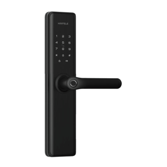
Product specifications Outside panel Inside panel Battery cover Touch keypad Card reader area Fingerprint sensor Safe handle Door handle switch Reset button Bottom cover CLOSE/OPEN button Reboot button Key cylinder Emergency power port Key cylinder Reboot button Emergency power port Mortise lock Sensor latch Deadbolt... -
Page 4: Components
Components 1. Battery cover (1 pc) 7. M6 Connecting screw bolt (2 pcs) 13. M5 Connecting screw bolt (3 pcs) 2. M6 mounting screw (2 pcs) 8. Bottom cover (1 pc) 14. Outside panel assembly (1 pc) 3. Inside panel assembly (1 pc) 9. -
Page 5: Prepare For Installation
Preparing for installation Check door open direction This product ts for all door open directions Left-in/Left-out/Right-in/Right-out Indoor Indoor Indoor Indoor Outdoor Outdoor Outdoor Outdoor When your door is Left-out or Right-in, please do the following two things 1. Change latch direction and directional screw 2. - Page 6 Preparing for installation 2. Change handle direction (For inside and outside panel) Please fix the screws in proper locations according to below diagram in the desired open direction. Screws Positioning disc Shield sleeve Mechanical key pick 1. Take out the 2 screws, 2.
-
Page 7: Installation
Installation Square shaft M6 Connecting screw bolt *2 Pressure spring Do not make the M5 Connecting mortise deadbolt screw bolt *3 come out. Spring: the big end is downward. 3. Pass the connection wire through the buttom bore. 4. Install the mounting plate with fixing screws Then align and insert square shaft into mortise holes tightly against the door surface. - Page 8 Installation 5. Place pressure spring and square shaft in the 6. Insert the connecting wires of front panel into the back panel in proper order. related sockets of the back panel. Then align and insert the square shaft into mortise hole, make the back panel fit against the door closely.
- Page 9 Installation 9. Please check handle, safe handle switch and mechanical key if they are working properly. Test if mechanical key works smoothly CLOSE after installation.
Need help?
Do you have a question about the DL7600 and is the answer not in the manual?
Questions and answers