Advertisement
Quick Links
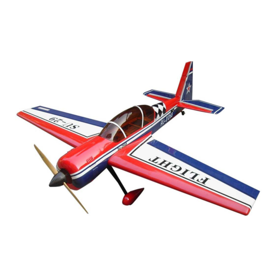
Wing Span:70.8in/1800mm;
Wing Area:62sq.dm;
Length:66.5in/1690mm;
CAUTION : this plane is not a toy!
Before use , please carefully read this manual.
●First-time builders should seek advice from people having building
experience in order to assemble the model correctly and to produce its
performance to full extent .
●Assemble this kit only in places out of children's reach!
●Take enough safety percautions prior to operating this model.
You are responsible for this model's assembly and safe operation!
●Always keep this instruction manual ready at hand for quick
reference,even after completing the assembly.
Flying Weight:3800g;
Radio:6channels 5servos;
Engine:26-30CC GAS;
P1
Advertisement

Related Manuals for Flight Model F136 SU-29 26-30CC


Summary of Contents for Flight Model F136 SU-29 26-30CC
- Page 1 Wing Span:70.8in/1800mm; Flying Weight:3800g; Wing Area:62sq.dm; Radio:6channels 5servos; Length:66.5in/1690mm; Engine:26-30CC GAS; CAUTION : this plane is not a toy! Before use , please carefully read this manual. ●First-time builders should seek advice from people having building experience in order to assemble the model correctly and to produce its performance to full extent .
-
Page 2: Main Wings
MAIN WINGS Connect the aileron and main wing with horns. Cut away covering film for the servo. Pull out the extention from the rib of the main wing. - Page 3 Find out the holes in each sides of fuselage, then remove the covering. Plastic Fixup the wings with plastic bolt bolts on both sides.
-
Page 4: Main Landing Gear
MAIN LANDING GEAR Gather the wheels,axles and collars as shown. Carbon Fiber Landing gear Wheel Pants Permanently tighten the axle to the gear strut by wrenches. Install wheel pants with two mounting bolts. - Page 5 Install the main landing gear on the bottom of the fuselage. Pay attention to:we have CB and AL landing gear for choice. and the assembly way is the same.
- Page 6 ELEVATOR AND RUDDER Elevator assemblies. Install elevator servos on each sides of tailplane. Elevator pushrod.
- Page 7 Rudder assemblies. Tighten the second loop through the brass swage tube.
- Page 8 Crimp the brass tube with a crimping tool or pliers. Rudder pushrod. Push rods Rudder servo arm...
-
Page 9: Tail Wheel
TAIL WHEEL Bend the tail landing gear to fit for the rudder and insert it into the rudder. Glue the tail wheel wire to the rudder securely. Install the tail wheel, and fasten the presser of the tail wheel to the stabilizer by screws. - Page 10 FUEL TANK wrap Place the hatch. Use two screws to secure it firmly.
- Page 11 Another method for the rudder and elevator servo installation Install the ball linkege connector.Calculate the length proportion between the servo arm and the horn.Rotate the ball linkage connector to an appropriate position. Connect the elevator and stabilizer with horns and U steel wire.
- Page 12 Insert elevator to the tailplane with U shape wire. Controled by only 1 elevator servo which is linked. ENGINE Gather the engine and spare parts as shown.
- Page 13 The finished picture as shown. Install the DLE 30CC as shown. Pay attention to:you have DLE and MLD for choice.
- Page 14 COWLING Mounting the cowling by wood screws.
- Page 15 CG POSITION & CONTROL THROWS...
- Page 16 Another scheme for choice. Flight Model MFG CO . ADD:No.10,Fu Ning Street,Xian Xi Industrial,Chang An Town,Dong Guan City,Guang Dong Province,China Tel: +86-769-85070618 / +86-769-81627996 / +86-769-89790965 Fax: +86-769-85091868 E-mail:info@flight-model.com / flight_model@126.com Web: http://www.flight-model.com/product/eindex.asp http://flight-model.preview.alibaba.com/...
Need help?
Do you have a question about the F136 SU-29 26-30CC and is the answer not in the manual?
Questions and answers