
Related Manuals for Metso ND9100H


Summary of Contents for Metso ND9100H
- Page 1 INTELLIGENT VALVE CONTROLLER ND9100H Rev. 2.2 Installation, Maintenance and Operating Instructions...
-
Page 2: Table Of Contents
General ..........7 DRAWINGS AND PARTS LISTS ....25 Mounting on EC and EJ actuators ..7 12.1 Exploded view and parts list, ND9100H. 25 Mounting on Metso actuators with 12.2 Exploded view and parts list, VDI/VDE mounting face ......7 ND9100H/K00 and ND9100H/I00 .. -
Page 3: Nd9000 Product Family Summary
1.1.5 Open solution 1.1.9 Predictive maintenance Metso is committed to delivering products that freely inter- ❑ face with software and hardware from a variety of manufac- Easy access to collected data with FieldCare software turers; and the ND9000 is no exception. This open ❑... -
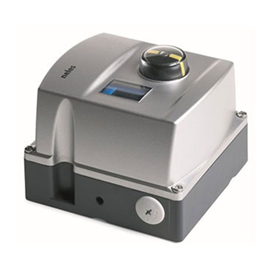
Page 4: Nd9100H Intelligent Valve Controller With Hart Communication
The valve controller is equipped with an identification face enabling local configuration. A PC with FieldCare plate sticker (Fig. 2). software can be connected to the ND9100H itself or to the control loop. The powerful 32-bit microcontroller controls the valve position. -
Page 5: Technical Specifications
7 ND91H 70 en Technical specifications Load voltage: up to 9.5 V DC/20 mA (corresponding 475 Ω.) ND9100H INTELLIGENT VALVE CONTROLLER Voltage: max 30 V DC General Polarity protection: -30 V DC Loop powered, no external power supply required. Over current protection: Suitable for rotary and sliding-stem valves. -
Page 6: Recycling And Disposal
Avoid earthing a welding machine in close proximity to Most parts have material marking. A material list is sup- an ND9100H valve controller. plied with the valve controller. In addition, separate Damage to the equipment may result. -
Page 7: Mounting
❑ Attach the bracket (1) to the actuator. The shaft (48) and tighten firmly. coupling of the ND9100H must fit into the ear (2) so ❑ Remove all protective plastic plugs (5 pcs.) from all that the pointer of the shaft washer (16) is located in pneumatic connections. -
Page 8: Table Of Contents
7 ND91H 70 en ❑ Mounting on linear actuator of Remove all plastic plugs from all actuator connec- tions (5 pcs.). Mount the metal plugs (54) with seal- nelesCV Globe ant to the unused controller connections at the See figure in Section 12.7. bottom of the controller. -
Page 9: Piping
FieldCare software. Connect the air supply to S (G1/4 ). Connect C1 and C2 (G1/4) to the actuator, see Fig. 6. ND9100H is connected direct to the EC or EJ actuator. Connections C1 and C2 (G1/4) must be plugged, see 12.3. - Page 10 7 ND91H 70 en Table 2 Piping Actuator Actuator piping Spool valve Stroke vol. / in 0.09 / 5 0.2 / 12 0.5 / 31 1.2 / 73 3.0 / 183 7.7 / 470 20.5 / 1250 Stroke vol. Spool valve / in 0.18 / 11 0.4 / 24...
- Page 11 7 ND91H 70 en DOUBLE-ACTING ACTUATOR Increasing input signal to open valve (shown) Default setting: DIR = OPE ROT = cC (close valve to clockwise) ATYP = 2-A PFA = CLO A0, CUTL and VTYP according to valve type 2. Increasing input signal to close valve (not recommended) Default setting: DIR = CLO ROT = cC (close valve to clockwise)
-
Page 12: Electrical Connections
Check using a feeler gauge that the clearance between the position indicator (109) and the electronics cover is 1 mm. NOTE: The ND9100H equals a load of 475 Ω in the current loop. HAZARDOUS LOCATION NONHAZARDOUS LOCATION Position Transmitter Exi barrier 53 µH... -
Page 13: Local User Interface (Lui)
Default / optional units of measurements Guided startup offers a fast view of the most critical Measurement Default unit Optional unit parameters of the ND9100H controller, actuator and valve position Percentage of full Angle, where 0 % valve configuration. After verifying the parameters the... -
Page 14: Configuration Menu
7 ND91H 70 en — brief push Fig. 11 Guided start-up NOTE: You may cancel any action by pressing the = button. Cancelling of operation returns user interface view one level up in menu hierarchy. — brief push Configuration menu Fig. -
Page 15: Configuration Parameters
7 ND91H 70 en ❑ Modify the parameter value by pressing + or - keys alternately until the desired value appears on the display. ❑ After the desired value is displayed, press the key ? to conclude the operation. 5.5.3 Signal direction, DIR The opening and closing direction of the valve with rais- ing current loop signal is defined by signal direction... - Page 16 5.5.8 Valve dead angle, A0 The α setting is made for Metso segment and ball valves. This setting takes into account the "dead angle" α of the ball valves. The entire signal range is then used for effec- tive valve opening 90°...
-
Page 17: Valve Travel Calibration
7 ND91H 70 en ❑ If the input signal is smaller than low cut-off, the lowing text: CALrun. After calibration the ND9100H scrolls valve will be fully closed. CALIBRATION SUCCESSFUL text. You may interrupt the cal- ❑ If the input signal is smaller than low limit, the ibration sequences at any time by pressing the = key. -
Page 18: Special Displays
Fig 19. The error message is displayed until the cause tion etc) during 1-point calibration, the calibration will of error is eliminated and the ND9100H unit is not end successfully. Check that the valve position is restarted, i.e. the power loop is momentarily discon- fully stable during this operation. -
Page 19: Hart Write Protection
7 ND91H 70 en HART write protection Prestage The ND9100H is delivered from the factory with the NOTE: default set as HART write protection OFF . Reading and The prestage must be handled carefully. In particular changing parameters is allowed. HART protection may... -
Page 20: Communication Circuit Board
7 ND91H 70 en 6.2.2 Installation ❑ Ensure that the gasket (174) is properly located in the groove on the bottom of the spool valve assembly. Mount the spool valve assembly on to the housing and tighten the M3 and M4 screws evenly. -
Page 21: Errors
7 ND91H 70 en Errors Warnings Display message Description Display message Description PRESTAGE CUT ERROR Prestage wire is cut or TOTAL OPERATION TIME Operating time exceeded connector is loose. WARNING limit. PRESSURE SENSOR 1 Actuator pressure sensor has VALVE FULL STROKES Valve stroke counter limit FAILURE failed. -
Page 22: Notifications
7 ND91H 70 en Notifications TROUBLE SHOOTING Mechanical/electrical defects Display message Description 1. A change in the valve position setpoint will not affect CALIBRATION Position calibration the position of the actuator SUCCESSFULL successfully performed. ❑ Supply pressure too low TEST CANCELLED Off-line test has been cancelled. -
Page 23: Nd9100H/K00, Nd9100H/I00 (With Limit Switches)
ND9100H/K00, ND9100H/I00 (WITH LIMIT SWITCHES) Introduction 9.1.1 General description ND9100H can be equipped with limit switches. ND9100H/K00 has 2 microswitches and ND9100H/I00 2 inductive proximity switches. Limit switches are used for electrical position indication of the valves and other devices. -
Page 24: Installing Nd9100H/K00 Or Nd9100H/I00 On A Valve Controller
Open Internal parts: Stainless steel and polymer Sealing: Nitrile and neoprene rubber Installing ND9100H/K00 or ND9100H/I00 on a valve controller The limit switch may be installed on an existing valve controller. ❑ If the valve controller is already mounted on an Fig. -
Page 25: Drawings And Parts Lists
7 ND91H 70 en DRAWINGS AND PARTS LISTS 12.1 Exploded view and parts list, ND9100H Item Description Spare modules Housing Exhaust cover Screw Shaft O-ring Washer Wave spring Bushing Grounding screw Electronics cover Screw Prestage cover Screw Screw Screw Screw... -
Page 26: Exploded View And Parts List, Nd9100H/K00 And Nd9100H/I00
7 ND91H 70 en 12.2 Exploded view and parts list, ND9100H/K00 and ND9100H/I00 Item Description Grounding screw Cover Screw Pointer Screw Local user interface (LUI) Housing Gasket Screw Screw Bracket Screw Bed of Local User Interface (LUI) Screw Screw Shaft... -
Page 27: Mounting Parts For E_05-14 Actuators, Rising Signal Opens Valve
7 ND91H 70 en 12.3 Mounting parts for EC05-14/EJ05-14 actuators, rising signal opens valve Item Description Screw Coupling Screw O-ring Coupler socket Screw E_05 - 14 O-ring Plug Plug (EJ only) ND9100 12.4 Mounting parts for B1C/B1J6-20 actuators ND9100 ND9100 VDI/VDE 3845 Neles attachment face... -
Page 28: Mounting Parts For B1C/B1J25-50, B1C502 And B1J322 Actuators
7 ND91H 70 en 12.5 Mounting parts for B1C/B1J25-50, B1C502 and B1J322 actuators Item Description Mounting bracket Draught piece Washer Screw Washer Screw Coupler socket Screw Plug (BJ actuators only) Plug ND9100 12.6 Mounting parts for Quadra-Powr® actuators Item Description Mounting bracket Screw Screw... -
Page 29: Mounting Parts For Linear Actuators Of Nelescv Globe
7 ND91H 70 en 12.7 Mounting parts for linear actuators of nelesCV Globe Set conical plug to the scale according to the stroke Item Description Washer Screw Conical plug Screw O-ring O-ring Mounting plate Feedback lever Screw Plug Plug... -
Page 30: Mounting Parts For Linear Actuators With Iec 60534 Mounting Face
7 ND91H 70 en 12.8 Mounting parts for linear actuators with IEC 60534 mounting face Feedback lever in horizontal position at mid travel of stroke. Stroke 10 - 120 mm Plane in the shaft in this position with feedback lever Scale on this side Allowed travel range 45–90°... -
Page 31: 12.9 Connection Diagrams
7 ND91H 70 en 12.9 Connection diagrams 12.9.1 ND9100H/K05 and ND9100H/K06 blue OPEN black blue CLOSED black Connection diagram shows limitswitch when actuator is in intermediate position. Switch A (upper) is activated at the open limit of the travel and switch K (lower) at the closed limit. - Page 32 7 ND91H 70 en 12.9.2 ND9100H/I0 blue OPEN brown blue CLOSED brown Factory adjustment: Active faces of proximity switches are covered when the actuator is in intermediate position. Active face A (upper switch) becomes free at open limit of travel and face K (lower switch) at closed limit.
- Page 33 7 ND91H 70 en 12.9.3 ND9100H/I56 black OPEN black black CLOSED black Factory adjustment: Active faces of proximity switches are free when the actuator is in the intermediate position. Active face A (upper switch) becomes covered at the open limit of the travel and face K (lower switch) at the closed limit.
- Page 34 7 ND91H 70 en 12.9.4 Control drawing HAZARDOUS LOCATION NONHAZARDOUS LOCATION Class I, Division 1 and 2, Groups A, B, C, D Class I, Zone 0, AEX ia, Group IIB/IIC T4/ T5/T6 T4: Ta = -40…80 °C T5: Ta = -40...65 °C T6: Ta = -40...50 °C Position Transmitter Exi barrier...
-
Page 35: Dimensions
7 ND91H 70 en DIMENSIONS ND9100 G1/4 0.75 15.5 0.61 M20 x 1.5 M6 x 12 0.16 29.5 1.16 F05-ø50(VDI/VDE3845) 35.4 1.39 G1/8 ø6/10 ND9100/I, ND9100/K F05-ø50(VDI/VDE3845) 35.4 G1/4 1.39 M6/10 0.55 0.74 G1/8 ø6 ø0.23 M20 x 1.5 0.78 G1/4 0.23 G1/8... -
Page 36: Ec Declaration Of Conformity
7 ND91H 70 en EC DECLARATION OF CONFORMITY... -
Page 37: Type Coding
7 ND91H 70 en TYPE CODING INTELLIGENT VALVE CONTROLLER ND9100H ND9100H WITH LIMIT SWITCH ND9100H/K00 OR ND9100H/I00 PRODUCT GROUP APPROVALS OF STANDARD ENCLOSURE VALVE CONTROLLER Intelligent Valve Controller FM / CSA certifications: - NI Class I, Division 2, Groups A, B, C, D, T4...T6. - Page 38 7 ND91H 70 en...
- Page 39 7 ND91H 70 en...
- Page 40 7 ND91H 70 en Metso Automation Inc. Europe, Levytie 6, P.O. Box 310, 00811 Helsinki, Finland. Tel. +358 20 483 150. Fax +358 20 483 151 North America, 44 Bowditch Drive, P.O. Box 8044, Shrewsbury, MA 01545, USA. Tel. +1 508 852 0200. Fax +1 508 852 8172 Latin America, Av.
Need help?
Do you have a question about the ND9100H and is the answer not in the manual?
Questions and answers