
Related Manuals for Metso Jamesbury Valv-Powr Value-Line D VPVL Series


Summary of Contents for Metso Jamesbury Valv-Powr Value-Line D VPVL Series
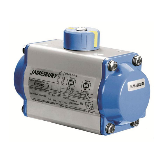
- Page 1 Valv-Powr® VPVL Mod D Value-Line® Double-Opposed Piston Actuators Installation, Maintenance and Operating Instructions...
-
Page 2: Table Of Contents
These instructions provide information about safe handling and operation of the actuator. If you require additional assistance, please contact the manufacturer or manufacturer’s representative. Addresses and phone numbers are printed on the back cover. See also www.metso.com/valves for the latest documentation. SAVE THESE INSTRUCTIONS! Subject to change without notice. -
Page 3: General
SPRING CARTRIDGE ASSEMBLY MAY RESULT IN SERIOUS PERSONAL INJURY! IF MAINTENANCE IS REQUIRED THE ENTIRE SPRING-RETURN ACTUATOR SHOULD BE DIRECTED TO A METSO SERVICE CENTER. SHUT OFF AND BLEED ALL SUPPLY LINES BEFORE INSTALLATION OR SERVICING THE ACTUATOR. BEFORE INSTALLING THE VALVE... -
Page 4: Installation
Metso desired, follow the disassembly procedure section 4.2. recommends inspecting actuators at least every five (5) Reverse the orientation of the pistons, then reassemble years. - Page 5 Re-tighten the end cap bolts and direct the complete actuator to a Metso Service Center for further maintenance. B. For spring return actuators, remove spring cartridges (17).
- Page 6 IMO-553 EN the bottom of the body (50). If the shaft (60) does not move freely, gently tap with a plastic mallet. C. Remove the top and bottom shaft bearings (6, 7) and top and bottom shaft o-rings (21, 22). Discard if replacing all soft parts.
-
Page 7: Assembly
IMO-553 EN Assembly C. Hold the body (50) in a horizontal position by inserting the top of the shaft in a vice, or inserting Prior to assembly, ensure that all components are clean the bottom of the shaft connection into a male drive and undamaged. - Page 8 IMO-553 EN F. Press the two pistons (40) simultaneously into the body (50) until the piston racks are engaged and rotate the body clockwise (if viewing the bottom of the actuator), or counter-clockwise (if viewing the top of the actuator), until the stroke is completed. G.
- Page 9 IMO-553 EN C. When the correct clockwise position is obtained, hold the adjusting screw (2) stationary while tightening the lock nut (4). D. Cycle the actuator/valve to the counter-clockwise end of travel and measure to determine if the valve is in the proper position.
-
Page 10: Safety Lockout Device
IMO-553 EN Figure 19 Double Acting Actuators: B. Open valve using air pressure. Note actuator will leak due to removed travel stop. A. Back off one travel stop screw, leaving it partially threaded in the end cap. Entirely remove the other C. - Page 11 IMO-553 EN 1. Removal of Stop Screws: B. Insert the Blocking Screw (226) and the Adjustment Screw (227) into the Actuator Body until the desired A. Remove from the Body both the existing Standard lock position is achieved then tighten the Special Stop Screws (02) together with Nut (04), Washer (03) Nut (228), see (Figure 21).
-
Page 12: Declutchable Manual Override (Do)
IMO-553 EN Declutchable Manual Override (DO) is achieved, hand tighten the stop screw and secure with the lock nut. The DO_ is a declutchable manual override quarter turn 5. Pull the knob outwards (3) then turn the selector (2) gearbox for single/double acting pneumatic actuators. To toward auto until the knob falls back into its locked prevent damage, it must be ensured that the actuator is not position. -
Page 13: Actuator Storage
For further information on spare parts and service or 1. If the actuators are not for immediate use, the following assistance visit our web-site at www.metso.com/valves. precautions must be taken for storage: NOTE: When ordering spare parts, always include the A. - Page 14 IMO-553 EN TABLE 3 - PARTS LIST FOR (FIGURE 24) Part # Part Description Material Octi-Cam (Stop Arrangement) Stainless Steel / Carbon Steel (1) Stop Cap Screw Stainless Steel Washer (Stop Cap Screw) Stainless Steel Nut (Stop Cap Screw) Stainless Steel Bearing (Piston Back) High Grade Polymer Bearing (Pinion Top)
- Page 15 IMO-553 EN TABLE 4 VPVL END CAP TORQUE VALUES End Cap Metric Torque Bolt Size Wrench Size in-lbs ft-lbs VPVL051 VPVL100 VPVL200 VPVL250 VPVL300 VPVL350 VPVL400 VPVL450 VPVL500 VPVL550 VPVL600 VPVL650 VPVL700 IMO 11/19...
- Page 16 Therefore, some of the situations in which the actuators are used are outside of the scope of this manual. If you have any questions concerning the use, application or compatibility of the actuator with the intended service, contact Metso for more infromation. HOW TO ORDER To specify a complete Valv-Powr Value-Line®...
Need help?
Do you have a question about the Jamesbury Valv-Powr Value-Line D VPVL Series and is the answer not in the manual?
Questions and answers