
Subscribe to Our Youtube Channel
Related Manuals for Metso Neles N1 Series


Summary of Contents for Metso Neles N1 Series
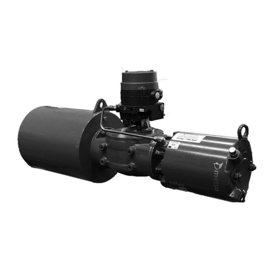
- Page 1 NELES® HIGH PERFORMANCE HEAVY DUTY SCOTCH YOKE ACTUATOR, SERIES N1 Installation, Maintenance and Operating Instructions...
-
Page 2: Table Of Contents
These instructions provide information about safe handling and operation of the device. If you require additional assistance, please contact the manufacturer or manufacturer’s representative. Addresses and phone numbers are printed on the back cover. See also www.metso.com/valves for the latest documentation. SAVE THESE INSTRUCTIONS! -
Page 3: General
Scope of the manual This instruction manual contains important information regarding the installation, operation and maintenance of Metso N1 series actuators. Please read these instructions carefully and save them for future reference. The manual can be changed or revised without any prior notice. -
Page 4: Specifications
6 N1 70 en Specifications Protection class: IP66, IP67 Ambient temperatures: Standard design -20° to 80 °C / -4° to 176 °F Maximum Supply pressure: Depends on model, See Table 3 Table 1 Stroke volume, dm - Single acting Cyl. Diam 1000 1100 1200 1300 Actuator Stroke volume, dm... -
Page 5: Safety Precautions
6 N1 70 en NOTE: MINIMUM STROKE MODEL OPENING/CLOSING Advisory and information comments provided to assist (mm) TIME (SECONDS) maintenance personnel to carry out maintenance proce- dures. WARNING FOR ATEX: If not observed, user incurs a high risk of severe dam- age to actuator and/or fatal injury to personnel. -
Page 6: Mounting And Demounting
These allow the installation position of the actuator to be Before installation please take care of the safety precau- changed in relation to the valve. Metso valves have a bevel tions mentioned in the Section 1.7. at the end of their shafts to facilitate installation. -
Page 7: Maintenance
Can significantly help to prevent unplanned downtime and in real terms reduce the total cost of ownership. Metso rec- ommends inspecting the actuators at least every five (5) years. - Page 8 6 N1 70 en For single acting actuator if port B is connected then check air leakage from exhaust port. For double acting actuator if port B is connected then check air leakage from exhaust port. NOTE: In order to ensure safe and effective operation, always use original spare parts to make sure that the actuator func- tions as intended.
-
Page 9: Maintenance Precautions Of The N1_E_C And N1_E_A Actuator
NOTE: If pneumatic pressure is not available to apply, use press the spring enough to move the yoke off the stop special Metso spanner for ring nut. screw of spring module side of the central block module. Step 6. Unscrew bolts (44) of rear side end cap (61) and remove end cap. - Page 10 6 N1 70 en Step 8. Remove hex cap screw /nut (38) with lock washer (37) from housing. Step 9. Remove spring module from actuator assembly, use Step 11. Fitment between top cover (12) and central block lugs provided on spring module assembly for lifting. (11) is tight, use screw driver as crowbar and put it in slot provided on central block cover to lift the cover.
- Page 11 6 N1 70 en 4.3.2 Spring Module Installation Step 1. To replace existing spring module first remove existing spring module from actuator refer chapter 4.3 sec- NOTE: tion 4.3.1 spring module removal. Skip procedure steps Review section 4.4.1 General Disassembly before proceed- from 2 to 4 for single acting.
- Page 12 Step 8. Install hex. Cap screw / stud thru housing in spring module and tighten to assembly the spring module with actuator. Step 10. Install o-ring seal (63) into the o-ring groove in the Step 9. Using special Metso spanners go thru the open end outboard end of spring module and then install rear cap (61).
- Page 13 6 N1 70 en 4.3.4 Pneumatic Cylinder Module Installation Step 1. Check to verify that o-ring seals (24), (33) are prop- Step 2. Using lifting equipment move the pneumatic cylin- erly fitted in its seal grove on the front cover (3) and guide der module up to central block module and align the piston rod (14) respectively.
-
Page 14: Actuator Disassembly
6 N1 70 en Actuator Disassembly CAUTION: Do not damage O-ring or O-ring grove while removing 4.4.1 General Disassembly top cover (12). WARNING: CAUTION: It is possible, that the actuator may contain a Spring module should be removed before starting pneu- dangerous gas and/or liquids. - Page 15 6 N1 70 en Step 9. Remove piston assembly (6) from tie rod. CAUTION: Step 6. The fit between cylinder tube (4) and rear cover (10) No not damage seals of guide bushing (7) while removing is very tight. Use screwdriver as crowbar to remove rear piston assembly (6).
- Page 16 6 N1 70 en Step 13. Remove 6 hex cap screw/nut (38) pneumatic cylinder assembly sides with lock washer (37) from central block housing (11). Step 14. Remove front cover (3) from actuator assembly Step 16. Remove retaining ring (36) to remove bearing with piston rod (9).
- Page 17 6 N1 70 en 4.4.3 Central block module disassembly NOTE: Stroke adjustment screw will be removed later in this pro- CAUTION: cedure. Spring module and pneumatic cylinder module should be removed before starting central block module removal NOTE: procedure. This procedure considers top cover (12) was removed (Review chapter 4.3 section 4.3.1 and 4.3.2).
- Page 18 6 N1 70 en Ste 6. Remove top roller (17) with yoke pin washer (16) from yoke (13) and yoke pin (16). Step 9. Remove bottom side bearing (46) of yoke (13) from central block housing (11). Step 7. Hold the yoke pin by hand and unscrew hex. Soc. Head set screw (51) from carrier (15) to remove yoke pin (16) from carrier.
-
Page 19: Actuator Reassembly
6 N1 70 en Actuator Reassembly 4.5.1 General reassembly CAUTION: Only new seals, which are still within the seal’s expectant shelf life, should be installed into the actuator being refur- bished. Remove and discard all old seals and gaskets. Parts should be cleaned to remove all dirt and other foreign material prior to inspection. - Page 20 6 N1 70 en Step 8. Install guide rod (14) in central block housing (11) and carrier (15). Step 5. Install the yoke assembly in the bottom bearing (46) of actuator with bottom side o-ring seal (28) Step 9. Install top cover (12) with o-ring (25) on central block housing (11) with the help of hex.soc.
- Page 21 6 N1 70 en 4.5.3 Pneumatic cylinder module reassembly NOTE: The actuator must be in appropriate over travel position Step 2. Install retaining ring (36) on guide bush. Step 1. Install outer o-ring (32) and rod seal (23) on guide bush, lubricate guide bush.
- Page 22 6 N1 70 en Step 6. Apply film of lubricant on tie rod (8) then install tie Step 10. Apply lubricant on cylinder tube (4) then install rod on front cover (3). cylinder tube thru piston (6) on front cover (3). Step 7.
-
Page 23: Stroke Screw Adjustment
6 N1 70 en Stroke screw adjustment 3. Loosen nut (43) & rotate stroke adjustment screw in counter clock wise (CCW) direction to set over travel and 1. Limit stop screw (42a, b) can be adjusted to get desired clock wise (CW) direction to set under travel. close &... -
Page 24: Tools
6 N1 70 en TOOLS For maintenance of the N1 series actuator, you will need a few common tools. Table 5 List of needed tools Tool style Location Tool size Allen key Allen key Allen key Ext. circlip Jaw spanner Jaw spanner Allen key 20, 41, *55... -
Page 25: Exploded Views And Parts List
6 N1 70 en EXPLODED VIEWS AND PARTS LIST Double acting actuators N1_D00 CYLINDER SIZES FROM 63 TO 150 Part no. DESCRIPTION QTY. SPARE CAT. Part no. DESCRIPTION QTY. SPARE CAT. CENTRAL BLOCK O-RING 1, 2 CYLINDER O-RING 1, 2 CYLINDER FRONT COVER O-RING 1, 2... - Page 26 6 N1 70 en CYLINDER SIZES FROM 200 TO 1000 31 39 7 35 6 8 30 29 36 9 24 23 50 52 Item no. DESCRIPTION QTY. SPARE CAT. Item no. DESCRIPTION QTY. SPARE CAT. CENTRAL BLOCK O-RING 1, 2 CYLINDER O-RING 1, 2...
-
Page 27: Single Acting Actuators N1_E_C And N1_E_A
6 N1 70 en Single acting actuators N1_E_C and N1_E_A CYLINDER SIZES FROM 63 TO 150 5 36 9 19 25 47 53 57 26 Item no. DESCRIPTION QTY. SPARE CAT. Item no. DESCRIPTION QTY. SPARE CAT. CENTRAL BLOCK O-RING 1, 2 CYLINDER O-RING... - Page 28 6 N1 70 en CYLINDER SIZES FROM 200 TO 1000 49 50 1 32 Item no. DESCRIPTION QTY. SPARE CAT. Item no. DESCRIPTION QTY. SPARE CAT. CENTRAL BLOCK O-RING 1, 2 CYLINDER O-RING 1, 2 CYLINDER FRONT COVER O-RING 1, 2 NAME PLATE O-RING 1, 2...
-
Page 29: Dimensions And Weights
6 N1 70 en DIMENSIONS AND WEIGHTS Dimensions double acting 'M'X'N' DEEP 4 NOS. X view Z view Wmax ØC MODEL T max N1X063 1/4'' NPT N1X080 1/4'' NPT N1X100 1/4'' NPT N1X125 1/4'' NPT N1A0100 1/4'' NPT N1A0125 1/4'' NPT N1A0150 3/8'' NPT N1A200... -
Page 30: Weights Double Acting
6 N1 70 en N1G0600 1'' NPT N1G0700 1035 1'' NPT N1G0800 1065 1'' NPT N1G0900 1095 1 1/2'' NPT N1G0700-2 1580 1'' NPT N1H0600 1187 1'' NPT N1H0700 1228 1'' NPT N1H0800 1253 1'' NPT N1H0900 1305 1 1/2'' NPT N1H1000 1251 1030... -
Page 31: Dimensions Single Acting
6 N1 70 en Dimensions single acting 'M'X'N' DEEP 4 NOS. X view Z view Wmax MODEL ØC T max ØY N1X063-E1-E5 1/4'' NPT N1X080-E1-E5 1/4'' NPT N1X100-E1-E4 1/4'' NPT N1X125-E1-E2 1/4'' NPT N1A0100-E7 1/4'' NPT N1A0100-E8-E11 1/4'' NPT N1A0125-E7 1/4'' NPT N1A0125-E8-E11 1/4'' NPT... -
Page 32: Weights Single Acting
6 N1 70 en MODEL ØC T max ØY N1G0600-E1-E4 2375 1'' NPT N1G0700-E1-E4 1035 2375 1'' NPT N1G0800-E1-E4 1065 2375 1'' NPT N1G0900-E1-E4 1095 2375 1 1/2'' NPT N1G0700-2-E1-E4 1580 2375 1'' NPT N1H0600-E3 1187 1480 1'' NPT N1H0700-E1 1228 2155 1'' NPT... -
Page 33: Attachment Dimensions
6 N1 70 en Attachment dimensions MOUNTING FACE DIMENSIONS ØTxW DEEP `G' X `H' DEEP 4 NOS. ØQ `G' X `H' DEEP `G1' X `H1' DEEP 4 NOS. `G' X `H' DEEP ØTxW DEEP 4 NOS. ØTxW DEEP ØQ 4 NOS. ØQ1 ØQ VIEW FROM-Z... -
Page 34: Type Code
6 N1 70 en TYPE CODE Heavy duty scotch yoke actuator 0250 * (NIL) * (NIL) Series Link type Neles heavy duty actuator Symmertric Frame size Cylinder type Single cylinder Dual cylinder Temperature range -20°...+80 °C Single / Double acting E01 ... - Page 35 6 N1 70 en...
- Page 36 6 N1 70 en Metso Flow Control Inc. Europe, Vanha Porvoontie 229, P.O. Box 304, FI-01301 Vantaa, Finland. Tel. +358 20 483 150. Fax +358 20 483 151 North America, 44 Bowditch Drive, P.O. Box 8044, Shrewsbury, M A 01545, USA. Tel. +1 508 852 0200. Fax +1 508 852 8172 South America, Av.
Need help?
Do you have a question about the Neles N1 Series and is the answer not in the manual?
Questions and answers