
Related Manuals for Metso Valvcon ADC Series


Summary of Contents for Metso Valvcon ADC Series
- Page 1 VALVCON® ADC-Series CONTINUOUS DUTY, UNIVERSAL ON/OFF & MODULATING ELECTRIC ACTUATORS With U2, UL2, UL3, U4, UL4, UL5, U6, UL6 & UL7 Options With “-UP” In The Model Number Installation, Maintenance and Operating Instructions...
-
Page 2: Table Of Contents
If you require additional assistance, please contact the manufacturer or manufacturer’s representative. Addresses and phone numbers are printed on the back cover. See also www.metso.com/electricactuators for the latest documentation. SAVE THESE INSTRUCTIONS! All trademarks are property of their respective owners. -
Page 3: General
CLASS II, DIV I, GR. E, F & G; CLASS III. ® WARNING: DO NOT OPEN WHILE ENERGIZED OR WHEN AN EXPLOSIVE ATMOSPHERE IS PRESENT METSO AUTOMATION 44 BOWDITCH DRIVE SHREWSBURY, MA 01545 USA 1-508-595-5083 (6) (5) (4) Description of ADC-Series Universal... -
Page 4: Universal Control Board P/N
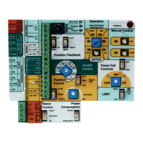
IMO-I4900 EN Universal Control Board P/N WARNING VCB00010 DANGEROUS VOLTAGES ARE PRESENT INSIDE THE ACTUATOR The Universal Control Board can be configured for either COVER UNLESS THE POWER SUPPLY TO THE ACTUATOR HAS BEEN “Two-Wire” or “Three-Wire” On/Off control, or “4-20mA SHUT OFF OR DISCONNECTED. -
Page 5: General Installation Information
IMO-I4900 EN GENERAL INSTALLATION 5 - MAN (MANUAL) – A continuous yellow LED indicates that INFORMATION Manual Control mode has been selected. The actuator will not respond to external control signals and the [CW] and [CCW] push buttons are enabled for manually driving the Interface actuator in either direction. -
Page 6: Operation Mode Selector Pot
IMO-I4900 EN are inside of the electronically saved travel stop positions, or some other increase in the torque load on the actuator. 11 - Battery Charging* – A continuous yellow LED indicates that the battery charging circuit is active to either charge or maintain the voltage on the Battery. -
Page 7: Cam Limit
IMO-I4900 EN 4.4.2 Cam Limit When “Cam” is selected as the limit type, two limit switches operated by the stainless steel cams on the output shaft extension are used to determine the exact positions where the actuator will stop at each end of CW and CCW travel. The bottom limit switch determines the clockwise stop position. -
Page 8: 12Vdc Or 24Vdc Power Wiring
IMO-I4900 EN On/Off Control Signal Wiring WARNING IF USING 24VAC TO POWER THE ACTUATOR, A DEDICATED POWER SUPPLY OR ISOLATION TRANSFORMER MUST BE USED. 12VDC or 24VDC Power Wiring If using 12VDC or 24VDC as the MAIN Input Power: 12/24 VDC must be supplied constantly to the Universal Control Board as follows: - Terminal 19 (DC POS) -
Page 9: Set Up And Calibration
IMO-I4900 EN On/Off Control Wiring On/O C ontrol Hot / L1 High V oltage P ower 115/230V AC Neut. / L2 Hot / L1 C W High V oltage Hot / L1 MID 115/230V AC Hot / L1 C C W mA / V DC - On / O C ontrol Opt. -
Page 10: Verify End-Of-Travel Settings
IMO-I4900 EN Set SPAN (typically CCW): 7.1.1 “4-20mA Current Analog” Control Turn the Mode Selector Dial to [SPAN] and press [ENTER] The actuator will modulate between positions in direct for 2 seconds. The [SPAN] LED will begin to flash. response to the change in the input current signal. Set 4 mA as the Zero position and 20mA as Span for normal operation Drive the actuator to desired counterclockwise position or set 4mA as Span and 20mA as Zero for reverse acting. -
Page 11: Set Up And Calibration
IMO-I4900 EN Positioning Control Wiring P os ition C ontrol Hot / L1 High V oltage P ower 115/230V AC Neut. / L2 mA / V DC - Opt. E xternal +24V DC F eedback mA / V DC + C W S witch 1 C OM Auxiliary S witches C C W S witch 2 C OM... -
Page 12: Verify End-Of-Travel Settings
IMO-I4900 EN Set MID: (if applicable) Align cover so that the override shaft will pass through the override bushing and carefully push it down so Turn the Mode Selector Dial to [MID] and press [ENTER] that the cover flange contacts the base flange. for 2 seconds. -
Page 13: Position Feedback And Status Indicators
IMO-I4900 EN POSITION FEEDBACK AND STATUS The 4-20mA Feedback circuit will power down if no INDICATORS impedance is measured on the output terminals in both Normal and Energy Save Mode operation. This is to stop any Position Feedback unnecessary power drain while the 4-20mA feedback circuit is not connected. -
Page 14: Power Fail Controls
Universal Control Board charging circuit, which is calibrated to provide the proper voltage and current for Manually Drive the Actuator (Using the Battery) During maximum battery pack life, or from a Metso recommended Power Outage (If using “Park” Power Fail Control selection) battery charger. -
Page 15: Board Installation / Replacement
IMO-I4900 EN BOARD INSTALLATION / BOARD REMOVAL REPLACEMENT 11.1 Step by Step Instructions for the Removal of a Universal ADC/LADC- 10.1 Safety Precautions Series Actuator Control Board: WARNING DANGEROUS VOLTAGES ARE PRESENT INSIDE THE ACTUATOR COVER UNLESS THE POWER SUPPLY TO THE ACTUATOR HAS BEEN SHUT OFF OR DISCONNECTED. -
Page 16: Board Installation
IMO-I4900 EN Remove the three Philips head screws that hold the VCB00010 Board in place with the #1 Philips screwdriver, and save them for later use. Figure 20 Connect the upper power supply cable and the auxiliary Figure 18 limit switch cables as shown in Figure 20. Unplug all cables attached to the VCB00010 and remove the board. -
Page 17: Reassembly
IMO-I4900 EN REASSEMBLY Figure 22 Re-install the board overlay. Figure 24 NOTE: For actuators including hazardous location certifica- tion. Prior to installing cover, inspect machined flange surfaces for any damage, scratches, or dents. Damage, scratches, or dents that will not fit completely in a circle having a diam- eter of 1/64”... -
Page 18: Default Settings And Modes
IMO-I4900 EN DEFAULT SETTINGS AND MODES Board Section Function Condition State Back of Board Torque Small Actuator Pot Mid Large Actuator Pot Full CW Heater Low Power Full CCW Battery (with battery installed) Sealed Lead Acid Pot 3/4 CW Battery (no battery installed) None Full CW Position Feedback... -
Page 19: General Operating Information
16.5 Lubrication Certifications Metso offers two versions of ADC-Series actuator enclosures: the “W” enclosure is weathertight, and the “WX” All rotating power train components are permanently enclosure which is weathertight and explosion-proof. -
Page 20: Specifications & Technical Information
IMO-I4900 EN SPECIFICATIONS & TECHNICAL INFORMATION Table 1 12VDC 24VDC 24VAC 115VAC 230VAC Duty Torque Cycle Cycle Current Cycle Current Cycle Current Cycle Current Cycle Current Output at/below Time Draw Time Draw Time Draw Time Draw Time Draw 40°C/104°F (sec/90°) (Amps) (sec/90°) (Amps) -
Page 21: Adc-Series Universal Control Board
IMO-I4900 EN 17.1 ADC-SERIES UNIVERSAL CONTROL BOARD Table 3 Control Board Specifications Input Impedance Voltage Input: 35K ohms (Analog Control) Current Input: 200 ohms Analog Control Signal May be either 4-20mA or 0-10VDC (selectable via on-board slide swithch) Fully compatible with ISA-S50. 1 as a type 4, class L, power isolated device. Input minus (-) and transmit minus (-) are tied together and isolated from power and earth ground. -
Page 22: Dimensions
IMO-I4900 EN 17.2 DIMENSIONS ADC-SERIES ENCLOSURES (150-600 LB-IN) Mounting Flange, ISO 5211 F05 / F07 Actuator Size Drive Option Drive Type Drive Size Depth 150-600 lb-in (12-50 lb-ft; 17-68 Nm) Standard Square 0.750 (19mm) 0.90 (22.9mm) 150-600 lb-in (12-50 lb-ft; 17-68 Nm) Option "I1"... -
Page 23: Adc-Series Actuators By Model Number
IMO-I4900 EN ADC-SERIES ACTUATORS BY MODEL NUMBER Table 4 How To Order - ADC-Series Electric Actuators (see note 1) Actuator Operating Enclosure Type Torque Board Options (see note 2) Other Options Series Voltage Order Description Order Description Order Description Order Code Description Order Description Code... -
Page 24: Additional Actuator Products And Accessories From Metso
IMO-I4900 EN ADDITIONAL ACTUATOR PRODUCTS • Economical NEMA 4/4X/7&9 solution AND ACCESSORIES FROM METSO • 12VDC & 24VDC voltages • 80% Duty Cycle V-Series • CSA (C US) Certified • Up to 3000 inch pounds (250 lb-ft; 339 Nm) for On/Off, •...
Need help?
Do you have a question about the Valvcon ADC Series and is the answer not in the manual?
Questions and answers