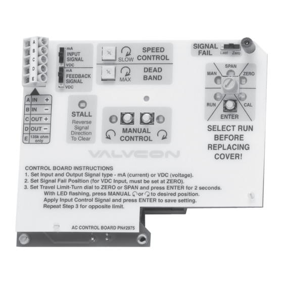
Metso VALVCON V-Series Installation, Maintenance & Operating Instructions
Electric actuators 115 vac and 230 vac with control board installed (option c)
Hide thumbs
Also See for VALVCON V-Series:
Summary of Contents for Metso VALVCON V-Series
- Page 1 VALVCON® V-Series ELECTRIC ACTUATORS 115 VAC AND 230 VAC With Iso/Readback Board Installed (Option “U”) Installation, Maintenance and Operating Instructions...
-
Page 2: Table Of Contents
These instructions provide information about safe handling and operation of the actuator. If you require additional assistance, please contact the manufacturer or manufacturer’s representative. Addresses and phone numbers are printed on the back cover. See also www.metso.com/electricactuators for the latest documentation. SAVE THESE INSTRUCTIONS! Subject to change without notice. -
Page 3: General
This instruction manual contains important information ACTUATOR AND/OR PERSONAL INJURY. regarding the installation, operation and maintenance of the Valvcon V-Series electric actuator. Please read these WARNING instructions carefully and save them for future reference. BEWARE OF MOVEMENT OF THE FINAL DRIVE ELEMENT AND ANY... -
Page 4: Operation
IMO-I5500 EN Position indication is available at terminals 5 and 6 on the Motor Board (for discrete end of travel indication), and at terminals D and E on the Iso/Readback Board (for analog position readback). Note: This option will fit all V-Series 115 & 230 VAC actuators with the letter “N”... - Page 5 IMO-I5500 EN IMO 10/17...
-
Page 6: Operation For On/Off Or Jogging
IMO-I5500 EN Wiring Diagram – Retransmit Only MOTOR CAPACITOR Motor Board CCW RED MOTOR RET BLACK CONNECTOR CW WHITE Motor Terminal 4 CW Hot (Must Connect) HEATER CW HOT HEATER Terminal 3 CCW Hot (Must Connect) OPTION Board CCW HOT Terminal 2 AC Common (Must Connect) CONNECTOR BRAKE SOLENOID... -
Page 7: Proper Actuator Cover Installation
IMO-I5500 EN travel, and the second cam, (from the bottom) controls Plug Pot connector into the 3-pin connector on the front the counter-clockwise end-of-tavel (See Figure 3). of the Iso/Readback Board (“J1”). Plug Iso/Readback Board into Motor Board (P/N VC002015) via 10-pin Move the actuator to the desired STOP position connector and secure to the existing bracket with Apply power according to desired mode of operation... -
Page 8: V-Series Standard Options
IMO-I5500 EN Optional Locking Exploded View Brake Assembly Motor Board Optional Retransmit Terminals 1 & 2 Terminals - Connect D&E 1 (AC Hot), 2 (Neutral) DC Control Signal Terminals - A, B & C Pot Connector AC Control Signal Terminals - F, G & H P/N VC002065 Board To install P/N VC002065... -
Page 9: Option "K" - Mechanical Brake
IMO-I5500 EN Option “K” – Mechanical Brake Option “S2” – Two Auxiliary Limit P/N VC099715 Switches P/N VC099000 The brake option prevents back-driving; it is required The extra switches and stainless steel cams provide dry on all butterfly valve and damper applications. It is also contacts and are fully adjustable to trip at any position. -
Page 10: Option "Y" - Keyed Output
Actuator Mounting Certifications The actuator may be mounted in any position including Metso offers two versions of V-Series actuator enclosures: upside-down. It must be firmly secured to a direct mount the “W” enclosure is weathertight, and the “WX” enclosure flange or sturdy mounting bracket. A minimum of four bolts which is weathertight and explosion-proof. -
Page 11: Operating Temperature Limits
To request a Return Authorization for an actuator within the IN DAMAGE TO THE ACTUATOR GEARING. ENSURE THAT THE warranty period, please consult your local Metso distributor. OVERRIDE IS FULLY DISENGAGED AND DO NOT USE EXCESSIVE FORCE WHEN MANUALLY POSITIONING ACTUATOR. DO NOT DRIVE THE ACTUATOR BEYOND THE TRAVEL LIMIT SETTINGS. -
Page 12: Specifications & Technical Information
IMO-I5500 EN SPECIFICATIONS & TECHNICAL INFORMATION Table 1 - Torque & VA Ratings Speed Torque Max Running Max Effective Peak (seconds Duty Output at VA Rating Current at Full Load Inrush Current (= .66 x) per 90˚ Cycle breakaway (True MS) Peak rush rotation) 115 VAC... -
Page 13: Dimensions
IMO-I5500 EN Dimensions LV-SERIES LV-SERIES ENCLOSURES Mounting Flange, ISO 5211 F07/F10 4 X M8-1.25 0.75" MIN. 4 X M10-1.5 0.75" MIN. 2.756" B. C. 4.016" B. C. 20 mm 10.8 SEE TABLE 22.4 mm 4.8 mm Female Square Drive Female Keyed Drive Actuator Size Drive Option Drive Type... -
Page 14: Exploded View
IMO-I5500 EN V-Series spare Parts List Exploded View Item No. Part No. Description Cover Cover screw VCK00012 Small enclosure (150 – 600 lb•in) VCK00013 Large enclosure (1000 – 3000 lb•in) Potentiometer/Cam Shaft Gears VC099090 90 degree Operation VC099180 180 degree Operation VC099270 270 degree Operation Override shaft (replacement only) -
Page 15: V-Series Actuators By Model Number
IMO-I5500 EN V-SERIES ACTUATORS BY MODEL NUMBER Table 3 Standard V/LV-Series Actuators (with “N” in model number before the voltage code) Board Options 1 Series Enclosure Type Torque Other Options Operating Voltage Code Description Code Description Code Description Code Description Code Description Weathertight... - Page 16 IMO-I5500 EN ADDITIONAL ACTUATOR PRODUCTS AND ACCESSORIES FROM METSO ADC-Series QX-Series • • Universal Control Board for On/Off and Modulating Up to 3000 inch pounds (250 lb-ft; 339 Nm) for On/Off applications applications • Up to 3000 inch pounds (250 lb•ft; 339 Nm) •...


Need help?
Do you have a question about the VALVCON V-Series and is the answer not in the manual?
Questions and answers