
Related Manuals for Edwards 18B4B


Summary of Contents for Edwards 18B4B
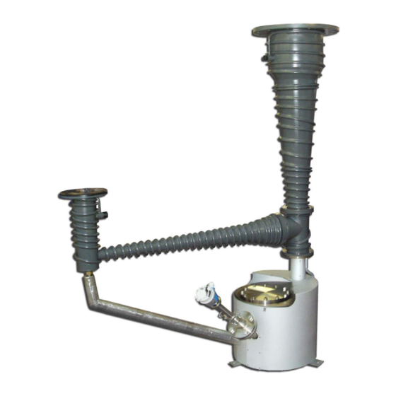
- Page 1 B06510880 Issue D Instruction Manual 18B4B Vapour Booster Pumps Original Instructions...
- Page 2 This page has been intentionally left blank.
-
Page 3: Table Of Contents
Filling procedure for adjustment of the fluid low level switch ..........29 3.13 Connect the optional fluid low level switch (if fitted) ............29 © Edwards Limited 2020. All rights reserved. Page i Edwards and the Edwards logo are trademarks of Edwards Limited. - Page 4 Spares ........................51 Accessories .......................51 Index ....................53 For return of equipment, complete the HS Forms at the end of this manual. Page ii © Edwards Limited 2020. All rights reserved. Edwards and the Edwards logo are trademarks of Edwards Limited.
- Page 5 Checklist of items .......................15 Vapour pump fluid thermal breakdown ................28 Maintenance plan .......................38 Fault finding ......................47 18B4B accessories .......................51 18B4B pump spares .....................52 © Edwards Limited 2020. All rights reserved. Page iii Edwards and the Edwards logo are trademarks of Edwards Limited.
- Page 6 ® Fomblin is a registered trademark of Solvey Solexis ® Apiezon is a registered trademark of M & I Materials, UK Page iv © Edwards Limited 2020. All rights reserved. Edwards and the Edwards logo are trademarks of Edwards Limited.
-
Page 7: Introduction
Description The 18B4B pumps are high performance vapour booster pumps, and have pumping speeds of up to 4000 l s The pumps are rugged and reliable and have high performance even with relatively high backing pressures. -
Page 8: Construction
Construction Refer to Figure 1 which shows a part-sectional view of the 18B4B pump. The pump has: A vertical top cone assembly (45) which incorporates the three diffusion pump stages (42, 6 and 5). A horizontal side cone assembly (14). -
Page 9: Over-Temperature Protection
Install an anti-moisture heater under the base of the pump. Switch on this heater when you switch off the pump. © Edwards Limited 2020. All rights reserved. Page 3 Edwards and the Edwards logo are trademarks of Edwards Limited. - Page 10 Application Note P40050000 from your supplier or Edwards. Figure 1 - Part sectional view of the 18B4B pump: key 1. Inlet 25. Heater retaining nut 2.
-
Page 11: Part-Sectional View Of The 18B4B Pump
B06510880 Issue D Figure 1 - Part-sectional view of the 18B4B pump © Edwards Limited 2020. All rights reserved. Page 5 Edwards and the Edwards logo are trademarks of Edwards Limited. - Page 12 B06510880 Issue D This page has been intentionally left blank. Page 6 © Edwards Limited 2020. All rights reserved. Edwards and the Edwards logo are trademarks of Edwards Limited.
-
Page 13: Technical Data
The performance data in Table 2 and in Figure 2 is for use of the pump with Edwards 201 fluid. The pumping speeds and throughput specified below and shown in Figure 2 were calculated from measurements made with partial pressure gauges. If total pressure gauges are used, the calculated values for pumping speeds are approximately 10% lower. -
Page 14: Mechanical Data
BSP female (with inch NPT male adaptors) Pump fluid data Note: A Edwards Material Safety Data Sheet for the fluid specified below is available on request. Table 4 - Pump fluid data Recommended fluid type Edwards 201 or AP201... -
Page 15: Electrical Data
Internal pump ‘O’ rings Fluoroelastomer Jet stack gasket Aramid fibre in nitrile rubber binder Boiler port gasket Carbon fibre in nitrile rubber binder © Edwards Limited 2020. All rights reserved. Page 9 Edwards and the Edwards logo are trademarks of Edwards Limited. -
Page 16: Pump Item Numbers
B06532240 380 V B06512380 B06522380 B06532380 440 V B06512440 B06522440 B06532440 480 V B06512480 B06522480 B06532480 18B4B pump, with Pt100 and fluid low level switch 200 V B06513200 B06523200 B06533200 220 V B06513220 B06523220 B06533220 240 V B06513240 B06523240 B06533240... -
Page 17: Typical Performance Curves
1. Pumping speed (l s ) against inlet pressure (mbar/Pa) for nitrogen 2. Throughput (mbar l s ) against inlet pressure (mbar/Pa) for nitrogen © Edwards Limited 2020. All rights reserved. Page 11 Edwards and the Edwards logo are trademarks of Edwards Limited. - Page 18 12 holes Ø25.4 on 431.8 PCD (ANSI inlet) 8 holes Ø11 on 387.4 PCD (EHVI inlet) ØA ØB ANSI 482.6 228.6 EHVI Page 12 © Edwards Limited 2020. All rights reserved. Edwards and the Edwards logo are trademarks of Edwards Limited.
- Page 19 B06510880 Issue D Figure 3 - Dimensions (mm) © Edwards Limited 2020. All rights reserved. Page 13 Edwards and the Edwards logo are trademarks of Edwards Limited.
- Page 20 B06510880 Issue D This page has been intentionally left blank. Page 14 © Edwards Limited 2020. All rights reserved. Edwards and the Edwards logo are trademarks of Edwards Limited.
-
Page 21: Installation
Only supplied if the corresponding optional device is fitted: refer to the list of Supplementary Publications at the end of the contents list. © Edwards Limited 2020. All rights reserved. Page 15 Edwards and the Edwards logo are trademarks of Edwards Limited. -
Page 22: Locate The Pump
Note that surfaces of the pump can get very hot during operation. Ensure that people cannot accidentally touch the hot surfaces of the pump. If necessary, fit guard rails. Page 16 © Edwards Limited 2020. All rights reserved. Edwards and the Edwards logo are trademarks of Edwards Limited. -
Page 23: Installation On A Vacuum System
Vacuum connections 3.4.1 System design WARNING You must fit a backing pressure-interlock. Consider the following points when you design your system: © Edwards Limited 2020. All rights reserved. Page 17 Edwards and the Edwards logo are trademarks of Edwards Limited. -
Page 24: Connect The Pump Inlet
The pump is tested with Edwards 201 fluid before delivery. Internal surfaces of the pump are therefore covered with a thin film of Edwards 201 fluid. Use acetone or another suitable cleaning solution to clean the pump flanges before you connect the pump to your vacuum system. -
Page 25: Cooling-Water Connections
Maintain the cooling-water inlet temperature as low as possible, preferably below 25 °C. Ensure that the cooling- water flow is satisfactory before you switch the pump heaters on: refer to Section 4.3. © Edwards Limited 2020. All rights reserved. Page 19 Edwards and the Edwards logo are trademarks of Edwards Limited. -
Page 26: Pump Fluid Drain Connection (Optional)
Check the earth (ground) resistance of the pump electrical supply before switch on. Figure 10 shows the recommended control circuit. Page 20 © Edwards Limited 2020. All rights reserved. Edwards and the Edwards logo are trademarks of Edwards Limited. -
Page 27: Connect The Supply To The Pump
3. Ensure that the earth (ground) wires on the terminal block cover (4) and the electrical box cover (1) are properly secured to the two earth (ground) points on the bottom of the electrical box. Figure 4 - Heater wiring connections © Edwards Limited 2020. All rights reserved. Page 21 Edwards and the Edwards logo are trademarks of Edwards Limited. -
Page 28: Terminal Block
B06510880 Issue D Figure 5 - Terminal block A. Top edge Figure 6 - Terminal block links for Star connections Page 22 © Edwards Limited 2020. All rights reserved. Edwards and the Edwards logo are trademarks of Edwards Limited. -
Page 29: Star Connection Wiring Diagram
Figure 7 - Star connection wiring diagram Figure 8 - Terminal block links for Delta connections Figure 9 - Delta connection wiring diagram © Edwards Limited 2020. All rights reserved. Page 23 Edwards and the Edwards logo are trademarks of Edwards Limited. -
Page 30: Recommended Control Circuit
3. Contactor 9. Contactor coil 4. Off load isolator 10. On switch 5. Fuses 11. Connection to thermal snap-switches 6. Electrical supply Page 24 © Edwards Limited 2020. All rights reserved. Edwards and the Edwards logo are trademarks of Edwards Limited. -
Page 31: Connect The Thermal Snap-Switches
You must adjust the boiler protection thermal snap-switch when you first switch on the pump: refer to Section 4.5. Connect the optional Pt100 temperature probe (if fitted) If you have ordered your 18B4B pump with the optional Pt100 temperature probe, the pump will be supplied with the probe fitted as shown in Figure 1, item 30. -
Page 32: Leak Test The System
Recommended pump fluids WARNING Do not use perfluoropolyether (PFPE) pump fluids in the 18B4B pump. The thermal breakdown temperature of PFPE fluids is near to the operating temperature of the pump. The thermal breakdown products of PFPE fluids are very dangerous. -
Page 33: Filling Procedure
General filling procedure Use the best fluid for your application. The pump is tested with Edwards 201 pump fluid and will contain traces of this fluid when supplied. (If you have ordered the pump for use with another fluid, the pump will be tested with the appropriate fluid.) You must refill the pump with the same type of fluid. -
Page 34: Filling Procedure For Adjustment Of The Fluid Low Level Switch
Connect the fluid low level switch outputs to your control or indicator equipment as described in the manufacturer’s instructions supplied. Refer to Section 2.6 for the output electrical characteristics. Page 28 © Edwards Limited 2020. All rights reserved. Edwards and the Edwards logo are trademarks of Edwards Limited. -
Page 35: Operation
Introduction WARNING Do not pump gases which are flammable at pressures in the operating pressure range of the 18B4B pump. If you do, this may result in an explosion or fire. If in doubt about the compatibility of gases with the use of the 18B4B pump, contact Edwards for advice. -
Page 36: Start-Up
1 M after the heater has been baked for 24 hours, then the heater is faulty and you must replace it with a new heater. Note: The following sections apply to 18B4B pumps which are operated in conjunction with a fully valved pumping system, as shown in Figure... -
Page 37: Adjust The Boiler Protection Thermal Snap-Switch (If Necessary)
Adjust the boiler protection thermal snap-switch (if necessary) Note: You must adjust the thermal snap-switch when the 18B4B pump is fully charged with fluid, is at operating temperature and is under vacuum. If you do not, the snap-switch may not operate at the correct temperature, and the pump may overheat. -
Page 38: Re-Admission Of Air To Your Vacuum System
1. Close the baffle valve. 2. Switch off the electrical supply to the 18B4B pump heater and allow the pump to cool for at least 2 hours. If you do not allow the pump to cool before you admit air, on re-evacuation the pump fluid will superheat and evolve vapour, which will pass into the backing pipeline. -
Page 39: Typical Pumping System
9. Backing valve 4. High-vacuum baffle-valve 10. Holding valve 5. High-vacuum gauge head 11. Holding pump 6. Work chamber 12. Backing pump © Edwards Limited 2020. All rights reserved. Page 33 Edwards and the Edwards logo are trademarks of Edwards Limited. - Page 40 B06510880 Issue D This page has been intentionally left blank. Page 34 © Edwards Limited 2020. All rights reserved. Edwards and the Edwards logo are trademarks of Edwards Limited.
-
Page 41: Maintenance
‘O’ rings. The pump may have overheated if it was misused, if it malfunctioned or if it was in a fire. Edwards Material Safety Data Sheets for fluorinated materials used in the pump are available on request;... -
Page 42: Maintenance Plan
If the pump fails to give satisfactory performance on a leak tight system, inspect the condition of the pump fluid as described below. 1. Allow the pump to cool and open it to atmospheric pressure. Page 36 © Edwards Limited 2020. All rights reserved. Edwards and the Edwards logo are trademarks of Edwards Limited. -
Page 43: Clean And Inspect The Pump
6. Loosen the 1 inch union nut on the fluid drain connection (see Note 1 above), and allow the pump fluid to drain into the container. © Edwards Limited 2020. All rights reserved. Page 37 Edwards and the Edwards logo are trademarks of Edwards Limited. -
Page 44: Clean The Main Pump Components
2. Use a cleaning solution (suitable for the pump fluid used) to clean the components. Page 38 © Edwards Limited 2020. All rights reserved. Edwards and the Edwards logo are trademarks of Edwards Limited. -
Page 45: Clean The Interior Components
We recommend that you replace all of the ‘O’ ring and gasket seals when you reassemble the pump. You must replace the cleaning port gasket. Refer to Section 7.3 for the Item Numbers of spare seals. © Edwards Limited 2020. All rights reserved. Page 39 Edwards and the Edwards logo are trademarks of Edwards Limited. -
Page 46: Prepare The Pump For Operation
Set the gap to 1.6 mm for use with Edwards 201 fluid. If you use the pump with another fluid, contact your supplier or Edwards for advice. Loosen and re-tighten the retaining screws as necessary to obtain the correct gap setting. -
Page 47: Clean The Radiation Shield
(4) and outlet (15) on the pump. 6. If necessary, disconnect the thermal snap-switch wires from the cooling-fail thermal snap-switch (Figure item 9). © Edwards Limited 2020. All rights reserved. Page 41 Edwards and the Edwards logo are trademarks of Edwards Limited. -
Page 48: Identify And Remove The Defective Heater
11. Carefully remove the defective heater (9) and the backing plate (6): pull the heater wires through the holes in the radiation shield (5). 12. Remove the defective heater (9) from the backing plate (6). Page 42 © Edwards Limited 2020. All rights reserved. Edwards and the Edwards logo are trademarks of Edwards Limited. -
Page 49: Replace A Heater
7. Heater sleeve 14. Half nut and washer 20. Cut-outs (in clamp plates) 8. Heater mounting stud 21. Earth (ground) stud © Edwards Limited 2020. All rights reserved. Page 43 Edwards and the Edwards logo are trademarks of Edwards Limited. -
Page 50: Assemble And Fit The New Heater
(ground) leakage, identify and rectify the problem. 10. Refer to Figure 13. Reconnect the electrical supply wires to the terminal block (16). Page 44 © Edwards Limited 2020. All rights reserved. Edwards and the Edwards logo are trademarks of Edwards Limited. -
Page 51: Check The Heater Clamp Plate And Retaining Nuts
A list of fault conditions and their possible causes is provided in Table 11 to assist you in basic fault-finding. If problems persist, contact your supplier or your nearest Edwards Service Centre. Table 11 - Fault finding Fault symptom Possible causes The pump will not start. - Page 52 The cooling-water temperature is too high. The pump is stalled due to a high gas load or high backing pipeline pressure. Page 46 © Edwards Limited 2020. All rights reserved. Edwards and the Edwards logo are trademarks of Edwards Limited.
-
Page 53: Storage And Disposal
Breakdown products which may be present if the pump fluid has been subjected to temperatures above the fluid breakdown temperature. Components or used pump fluid which have been contaminated with dangerous process substances. © Edwards Limited 2020. All rights reserved. Page 47 Edwards and the Edwards logo are trademarks of Edwards Limited. - Page 54 B06510880 Issue D This page has been intentionally left blank. Page 48 © Edwards Limited 2020. All rights reserved. Edwards and the Edwards logo are trademarks of Edwards Limited.
-
Page 55: Service, Spares And Accessories
The majority of these employ service engineers who have undergone comprehensive Edwards training courses. Order spare parts and accessories from your nearest Edwards company or distributor. When you order, please state for each part required: Model and Item Number of your equipment ... -
Page 56: Spares
Cooling-fail thermal snap-switch B02302000 Boiler protection thermal snap-switch B06401113 This adaptor flange is required to fit the P12R12A baffle and isolation valve to the 18B4B pump, and is only available for EHVI flanged pumps. Table 13 - 18B4B pump spares Spare... - Page 57 2 inch backing union ‘O’ ring (EHVI) H02106159 Heater spares packs contain heaters, crimps, terminals, wires and ceramic insulation beads. † As marked on the heater. © Edwards Limited 2020. All rights reserved. Page 51 Edwards and the Edwards logo are trademarks of Edwards Limited.
-
Page 58: Index
Reassemble the pump Disposal Recommended pump fluids Re-evacuation of your vacuum system Electrical data Replace a pump heater Electrical safety Rough pumping © Edwards Limited 2020. All rights reserved. Page 53 Edwards and the Edwards logo are trademarks of Edwards Limited. - Page 59 Spares Start-up Storage and disposal System design Technical data Temperature indication Tools and equipment required Unpack and inspect Vacuum connections Warnings Page 54 © Edwards Limited 2020. All rights reserved. Edwards and the Edwards logo are trademarks of Edwards Limited.
- Page 60 Jana Sigmunda 300 Burgess Hill Lutín , 78349 West Sussex Czech Republic RH15 9TW T: +42(0) 580 582 728 documentation@edwardsvacuum.com The product specified and listed below • 18B4B Vapour Booster • B065-10-XXX B065-20-XXX B065-30-XXX B065-11-XXX B065-21-XXX B065-31-XXX • • B065-12-XXX B065-22-XXX B065-32-XXX •...
- Page 61 You must retain the signed legal declaration for future reference This declaration becomes invalid if modifications are made to the product without prior agreement. Signed for and on behalf of Edwards Ltd Andries De Bock – Vice President Engineering Jan Vecera – General Manager...
- Page 62 ADDITIONAL LEGISLATION AND COMPLIANCE INFORMATION EMC (EU, UK): Class A/B Industrial equipment This product is not in scope: it has no active electronics and is inherently benign. RoHS (EU, UK): Material Exemption Information This product is compliant with the following Exemptions Annex III: 6(c) Copper alloy containing up to 4% lead by weight •...
- Page 63 This page has been intentionally left blank.
- Page 64 edwardsvacuum.com...
Need help?
Do you have a question about the 18B4B and is the answer not in the manual?
Questions and answers