Table of Contents
Advertisement
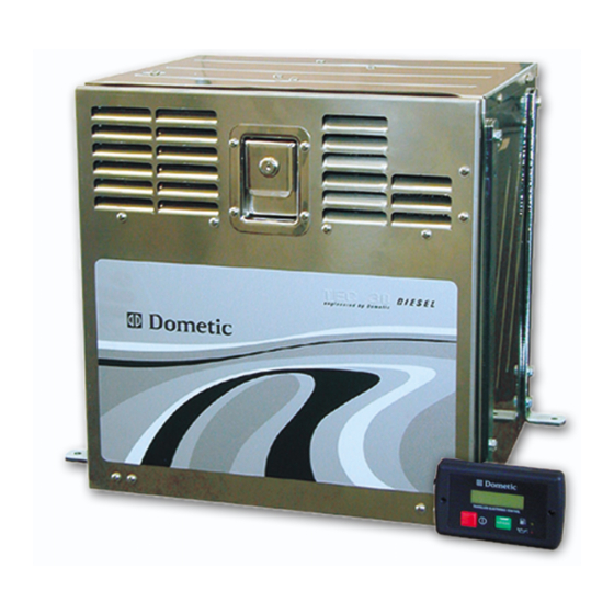
TEC 30
D I E S E L G E N E R A T O R
Operation, maintenance and installation manual
Libretto istruzioni per l'uso, la manutenzione e l'installazione
Betriebs-, Wartungs- und Installationsanleitung
Manuel d'utilisation, d'entretien et d'installation
Bedienings-, onderhouds- en installatiehandleiding
Manual de instrucciones para el uso, mantenimiento e instalación
Manual de instruções de uso, manutenção e instalação
Handbok för användning, underhåll och installation
Käyttö-, huolto- ja asennusohje
Bruks- vedlikeholds- og installasjonsanvisning
Betjenings-, vedligeholdelses- og installationsvejledning
Advertisement
Table of Contents

Subscribe to Our Youtube Channel
Related Manuals for Dometic TEC 30


Summary of Contents for Dometic TEC 30
- Page 1 TEC 30 D I E S E L G E N E R A T O R Operation, maintenance and installation manual Libretto istruzioni per l’uso, la manutenzione e l’installazione Betriebs-, Wartungs- und Installationsanleitung Manuel d’utilisation, d’entretien et d’installation Bedienings-, onderhouds- en installatiehandleiding Manual de instrucciones para el uso, mantenimiento e instalación...
- Page 2 La garantie Européenne Med Dometic kan du føle deg hjemme overalt. Takk for at du bestemte deg for å kjøpe Dometic vous offre, où que vous soyez, la possibilité de profi ter partout de votre matériel.
- Page 3 ©DOMETIC - 2004 All rights reserved - Printed in Italy - No part of this manual may be reproduced, copied or transmitted in any form or by any means without prior written permission from DOMETIC. Figures, descriptions, references and technical data contained in this manual are given as mere example and are not binding.
- Page 4 The Manufacturer’s warranty does not extend to Product failures, defects or damage arising from and/or attributable to a wrong installation. The Consumer is entitled to let the Product be installed by an authorised dealer, not bound by Dometic. The warranty extends to failures or defects in the gen-sets which shall become apparent within the warranty period.
-
Page 5: Table Of Contents
Extraordinary maintenance..........22 Brukerveiledning og manual til vedlikehold og installasjon Generator TEC 30 wiring diagram............24 TEC 30 wiring diagram - 2 TEC in parallel......25 Brugervejledning og manual TEC 30 spare parts table............. 26 til vedligeholdelse og installation Generaattori... -
Page 6: General Information
Information on the protection of the environment. Manufacturer’s data Manufactured by WTA v.Virgilio,3 Forlì-Italy Conformity marking PRODUCT No. MODEL SERIAL Model/Serial number xxxxxxxx 958 500 221 TEC 30 Year of manufacture Date 2003 Voltage V230 Output max W2900 Technical data Frequency Hz 50... -
Page 7: Safety
General information 1 • The company Dometic is not responsible for any damage caused by Exhaust gases contain carbon monoxide, an extremely poisonous generator malfunctions. gas, which is odourless and colourless. Avoid inhaling exhaust gases. Do not run the engine of the generator in a closed garage 1.3 Safety... -
Page 8: Description Of The Generator
1.7 Fuel Warning All diesel oils which satisfy the following specifications are suitable: The TEC 30 generator has been designed and produced to be used only on caravans, motor homes and commercial vehicles. EN 590 or Therefore it has not been designed to be used on other types of vehicles DIN 51601 - DK or or on any kind of watercraft. -
Page 9: Operating Description
General information 1 1.8 Operation description The main elements of the TEC 30 generator are: an engine (a), a permanent magnet alternator (b), an inverter (c), an internal control panel (d), a terminal board (e) and an external control panel (f). -
Page 10: External Control Panel
OIL INDICATOR: indicates a low oil level and the engine automatically stops EMERGENCY STOP SWITCH: stops the generator immediately in an emergency CUT OUT SWITCH: continuous current thermal cut out protection user’s manual TEC 30... -
Page 11: Technical Data
W W W W W ± ± ± ± ± ± ± ± ± ± % % % % % 1 1 1 1 1 6 5 . 6 5 . 6 5 . 6 5 . user’s manual TEC 30... -
Page 12: Display Messages
1 General information 1.12 Table describing the alarm messages appearing on the display l l i “ . ” user’s manual TEC 30... -
Page 13: Routine Maintenance
Perform all of the checks making sure the generator is in a horizontal standard are used. position. IMPORTANT: Remember to reconnect the positive pole (+) of the vehicle’s battery and set the switch back to “I” (ON) once you have finished the checks. user’s manual TEC 30... -
Page 14: Installation Instructions
Use the pre-printed cardboard sheet supplied with the package as a shape template to secure AG129/ST brackets onto the supporting wall. Secure the generator unit onto the hanging brackets with the vibration dampers supplied. Mount the bent exhaust pipe and secure the flexible connecting pipe with clamps to the additional muffler user’s manual TEC 30... - Page 15 Mount the straight exhaust pipe and secure the flexible connecting pipe with clamps to the additional muffler. Ensure that the flexible connection pipe is not overbent once secured. The minimum bending radius should be the same as recommended in the figure. user’s manual TEC 30...
-
Page 16: Instructions For Installing The Exhaust Terminal
The accessory AG134 is available upon request to improve the soundproof. WARNING Do not make any sharp bends in the hose which could obstruct the exhaust gas. EXTENSION FIXING AG163 (OPTIONAL) EXHAUST EXTENSION TEC 30 MUFFLER AG125 AG134 (OPTIONAL) user’s manual TEC 30... - Page 17 Installation instructions 2 Instructions for installing the exhaust system AG163 user’s manual TEC 30...
- Page 18 2 Installation instructions Instructions for installing the exhaust system AG163 AG163 AG163 user’s manual TEC 30...
-
Page 19: Instructions For Installing The Fuel Tank
The fuel tank should be installed with the tank basis at a maximum depth of 1.5 meters below the lower edge of the generator box. For safety reasons ensure not to mount the generator box top edge higher than the tank top edge. TANK MAXIMUM LOWER EDGE Max 1.5m TANK MAXIMUM TOP EDGE user’s manual TEC 30... -
Page 20: Instructions For The Electrical Connection
2 Installation instructions 2.3 Instructions for the electrical connection The Dometic generator is a source of alternate 230V 50Hz tension, 2 2 2 2 2 2 2 2 2 2 2 2 2 2 2 2 2 2 2 2 able to cope with various power needs. - Page 21 External control panel connection (+) Plus Choose the desired position inside the vehicle, use the extension lead pole (supplied) to connect the external control panel to the internal control panel of the generator. (-) negative pole Inserts user’s manual TEC 30...
-
Page 22: Troubleshooting, Maintenance, Recycling
The ge ne ra tor sta rts, the n stops a nd displa y “ ge ne ra tor a lle rt” m e ssa ge The produce d curre nt oscilla te s user’s manual TEC 30... -
Page 23: Checks - Nature And Service Intervals
. t s i t a t l i f . t n t - y i t a l i o t l i f o i t i x i t n i user’s manual TEC 30... -
Page 24: Extraordinary Maintenance
Refill the generator Limit stop screw Fixing with oil of the recommended type, through the oil filler. screw The quantity of oil is: Internal position Oil drain plug 0.9 Litres user’s manual TEC 30... - Page 25 If the air filter is dirty this reduces the flow of air to the engine. Therefore, to prevent malfunctions we recommend checking the state of the filter periodically, and more often if you are using the TEC 30 in particularly dusty areas.
-
Page 26: Tec 30 Wiring Diagram
TEC 30 WIRING DIAGRAM DESCRIPTION THREE-PHASE WINDING AUXILIARY WINDING CYAN CYAN AUXILIARY WINDING CYAN INVERTER MODULE YELLOW BLACK BLACK YELLOW 9-PIN CONNECTOR WHITE WHITE 12V REGULATOR 0/1 EMERGENCY STOP SWITCH PRESSURE CONTROL DEVICE START RELAY STARTING MOTOR 9-PIN CONNECTOR HATZ 6-PIN CONNECTOR M... -
Page 27: Tec 30 Wiring Diagram - 2 Tec In Parallel
WIRING DIAGRAM - 2 TEC30 IN PARALLEL MODE For parallel connection of 2 TEC30 follow the diagram in the picture . LOAD AG 113 (Accessory sold upon request) Ø 2.5 mm TEC 30 MAINS Ø 2.5 mm 2 Ø 4 mm Ø 4 mm BATTERY Ø... -
Page 28: Tec 30 Spare Parts Table
TEC 30 SPARE PARTS TABLE accessory accessory AG129 AG164 OPTIONAL OPTIONAL AG163 OPTIONAL AG165 user’s manual TEC 30... - Page 29 TEC 30 SPARE PARTS TABLE H O S E C L A M P 1B20V ENGINE TERMINAL STATOR TERMINAL S IL E N C E R ROTOR BIPOLAR SWITCH V IB R A T IO N D A M P E R...
Need help?
Do you have a question about the TEC 30 and is the answer not in the manual?
Questions and answers