
Subscribe to Our Youtube Channel
Related Manuals for Kval 995-H


Summary of Contents for Kval 995-H
- Page 1 Operation and Service Manual Published: March 5, 2021 Innovation, Quality & Honesty 995-H Jamb Routing System...
- Page 2 Proprietary Notice This Manual is confidential and contains proprietary information and intellectual property of KVAL Inc., and is to be used solely by Customer as an operating manual for KVAL Inc. machines. Neither this Manual nor any of the information contained herein may be reproduced or disclosed under any circumstances without the express written permission of KVAL Inc.
- Page 3 KVAL 995-H Operation and Service Manual Your Feedback is Welcome: NOTE: KVAL 995-H Operation and Service Manual...
- Page 4 KVAL 995-H Operation and Service Manual...
-
Page 5: Table Of Contents
Download Application .................1-16 Safety Sign-Off Sheet .............. 1-19 A Note to the Operator................1-19 Operation of the 995-H Chapter 2 Operator’s Tour ................ 2-2 The 995-H Process Summary ..............2-2 Machine Components................2-2 Top View of Machine................2-3 KVAL 995-H Routing and Hinge Application System... - Page 6 Description of the Six Light Panel ............2-16 About Switches and Sensors........... 2-17 Quick Start ................2-19 Powering Operations for the 995-H ......... 2-21 How to Power Up the 995-H ...............2-21 Home the 995-H .................2-22 How to Power Down the 995-H ............2-22 Emergency Shutdown and Recovery ..........2-23...
- Page 7 Clean inside Hopper ................4-12 72,000 Cycle Maintenance Steps ..........4-13 Inspect Nuts and Bolts................4-13 Electrical .....................4-13 Computer Backup ................4-13 Wash Filter and Lubricator Bowls ............4-13 Tool Changing Schedule............4-14 Maintenance NO-GOES ............4-16 KVAL 995-H Routing and Hinge Application System...
- Page 8 Air Input with Lubrication ..............4-28 Air Line Without Lubricator ..............4-29 Replacing Tooling in the Front Section ........4-30 Tool Locations in the 995-H Carriage Head........4-30 How to Access to Bit Assemblies............4-31 Remove and Replace the Router or Pre-Drill Bits (Point to Point) ..4-31 Remove and Replace the Screwdriver Bits ........4-33...
- Page 9 Troubleshooting Electrical Problems ........5-18 If the Power Stops During Normal Operation ........5-18 Troubleshooting with the Status Light Panel ......5-20 Network System Overview............5-24 Connections to Servo Drives ..............5-24 Symptoms and Possible Causes ..........5-25 KVAL 995-H Routing and Hinge Application System...
- Page 10 Table of Contents KVAL 995-H Operation/Service Manual...
-
Page 11: Chapter 1 At A Glance
Introduction to the 995-H CHAPTER 1 This chapter provides an overview of the KVAL 995-H Routing and Hinge Application System Included is important safety Information and Lockout Tagout procedures. Chapter 1 at a Glance The following information is available in this chapter: Summary of Chapter TABLE 1- 1. -
Page 12: Overview Of The
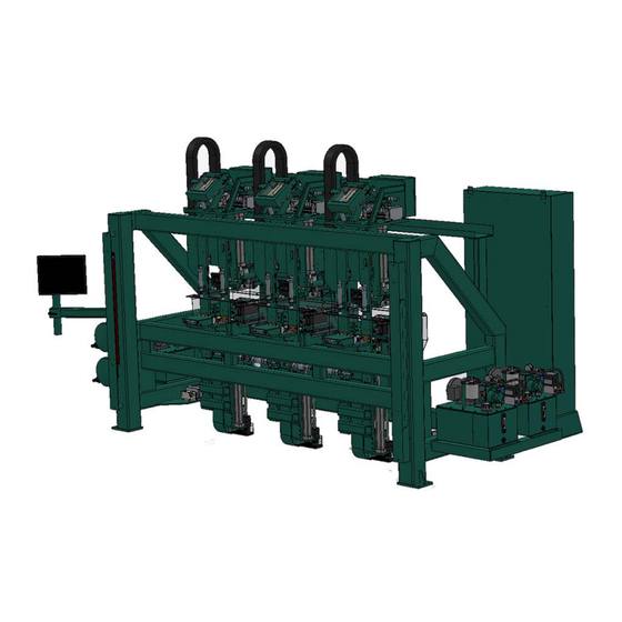
6'-8" and 7'-0" jambs for three hinges and 8'-0" jambs with four hinges. The 995-H is equipped with the Kval Three Shooter Screw gun, which is supported on ball bear- ing equipped steel wheels, is mounted on an overhead track that is precisely aligned to ensure the hinge is properly positioned into the pocket at each hinge location. -
Page 13: About This Manual
Descriptions of how to power machine line, and operator inter- face user screens. System IT Descriptions of the PLC system, Administration and computer system. Maintenance Maintenance steps for the machine line Troubleshooting Troubleshooting tips and theory of operation. KVAL 995-H Operation/Service Manual... -
Page 14: Safety First
Safety First! Safety First! Failure to do so can result in dam- age to equipment and/or serious injury to personnel. Safety Sheet Sign-Off Sheet Safety Terminology of Labels DANGER WARNING CAUTION Safety Guidelines Training... - Page 15 Before performing any mainte- nance or repairs on this machine turn off the main air disconnect. Lockout and tagout this connection. See “Lockout Tagout Procedure” on page 1-9. KVAL 995-H Operation/Service Manual...
- Page 16 Safety First! Electrical still power on the top side of the disconnect switch must be installed at all locations Before Conducting Maintenance Laser Warnings...
- Page 17 Safety First! Compliance with Codes and Regulations Other Hazard Control Action Report a Hazard STOP Before You Report an Accident Follow Your Company’s Safety Procedures...
-
Page 18: Lockout-Tagout Guidelines
O..OFF! Shut off all power sources and isolating devices P..Place lock and tag E..ENERGY: Release stored energy to a zero-energy state R ..Recheck controls and test to ensure they are in the “OFF” state KVAL 995-H Operation/Service Manual... -
Page 19: Lockout Tagout Procedure
Turn Switch to the Lock and Tag out Insert Lock into hole. OFF position Note: When multiple people are working on the machine, each person needs to have a lock on the handle in the extra holes provided. KVAL 995-H Operation/Service Manual... -
Page 20: Lockout Tagout Air Supply
The lock and tag can now be removed (only by the person(s) who placed them), and the machine can be re-energized. The tags must be destroyed and the locks and keys returned to the lockout center. KVAL 995-H Operation/Service Manual 1-10... -
Page 21: Zero-Energy To Start-Up
Replace Guards Replace all equipment guards. If part of equipment cannot be properly adjusted after start-up with guard on, contact the KVAL Service team. See “Getting Help from KVAL” on page 1-13. Check Controls Confirm that all switches are in the “OFF”... - Page 22 Be sure to follow the P-R-O- P-E-R lockout/tagout procedures, and that those around you do also. Close the Cage Gate Verify all cage gates are securely closed. Ensure all safety protocols are in effect. KVAL 995-H Operation/Service Manual 1-12...
-
Page 23: Getting Help From Kval
Getting Help from KVAL Getting Help from KVAL Air Driven Machines Pre -2019 Machines, look for the brass plate. -
Page 24: Kval Return And Warranty Policy
KVAL Return and Warranty Policy KVAL Return and Warranty Policy KVAL's goal is to provide customers with high quality products. If, for any reason, you are not completely satisfied with your purchase, please contact us at: Email: parts@kvalinc.com +1 (800) 553-5825 Phone: •... -
Page 25: Customer Errors
Kval provides a warranty to products that are deemed defective. Within 30 days of discovery of said defect, please notify Kval, but no more than one (1) year after delivery will the product be covered under Warranty. The repair, replacement, or payment in the manner described above shall be the exclusive remedy of Buyer for breach of Kval’s warranty or for claims based upon failure... -
Page 26: How To Download The Service Application
How to Download the Service Application How to Download the Service Application Download Application Support Note: Sample of Google Browser: Located at the bottom left of the screen. Sample of i.e Explorer: Located at the bottom of the screen. select the arrow and choose Save and Run... - Page 27 Session code: An internal number to track this machine. It is auto filled. Your Name Field: Enter your name. The KVAL tech- nician will use this field to identify this machine. Description: Enter machine Serial number and issue.
- Page 28 How to Download the Service Application Page Intentionally Left Blank KVAL 995-H Operation/Service Manual 1-18...
-
Page 29: Safety Sign-Off Sheet
Note: It is recommended you make a copy of this sheet for new operators. If a copy is needed, you may download a PDF at the KVAL website (http://www.kvalinc.com). You may also contact our Service Department at (800) 553-5825 or email at service@kvalinc.com. - Page 30 Safety Sign-Off Sheet KVAL 995-H Operation/Service Manual 1-20...
- Page 31 Operation of the 995-H CHAPTER 2 This chapter describes components, assemblies, and the user interface of the KVAL 995-H Door Hanging System. The content is geared to help operators understand the basic operation of the 995-H. Included are instructions to calibrate the machine and run a door.
-
Page 32: Operator's Tour
Operator’s Tour Operator’s Tour This section takes you on a tour of the 995-H Jamb Processing machine The 995-H Process Summary • Cut a hinge pocket on a jamb (Carriage Assembly) • Drill pilot holes for the hinge screws (Carriage Assembly) •... -
Page 33: Top View Of Machine
Creates Infrared Beam. If Beam is broken Machine Stops. Electrical Panel # 2 Operator Station: Touch Screen Three Shooter Fluid Machine Controls Pump Assemblies Identification of Key Assemblies of 995-H FIGURE 2-1. KVAL 995-H Operation/Service Manual... -
Page 34: Front Section
Safety Curtain X2 and secure the hinge to the jamb. Located on each side of the front section of the machine. Creates Infrared Beam. If Beam is broken Machine Stops. Front View of 995-H FIGURE 2-2. KVAL 995-H Operation/Service Manual... -
Page 35: Operator Station
Front Section Operator Station The 995-H includes a LCD touch screen monitor and machine controls to operate the machine. Operator Interface Screen: Touch Screen to operate machine. Control Transformer Activate to power up the Start/Stop system Activate ready the pro- See “How to Power Up the... -
Page 36: About The Safety Curtain
This may cause misalignment, if the system is mis- aligned the machine will not start Receiver Emitter Receiver Emitter Receiver Emitter Breaking of any beam stops the machine Machine in operation Location of Safety Curtain Arrays FIGURE 2-4. KVAL 995-H Operation/Service Manual... -
Page 37: About The Three Shooter And Hinge Carriage
Front Section About the Three Shooter and Hinge Carriage Hopper Screw Tracking Plate: 3 Shooter Screw Delivery System: Screw Driver Assembly: Hinge Placement Assembly: Hinge Carriage: Router: Pre-Drill: Chisels (X2): Hinge Carriage Overview FIGURE 2-5. KVAL 995-H Operation/Service Manual... -
Page 38: Hinge Carriage
• A pre-drill to drill pilot holes in the hinge pockets to ready the insertion of screws • by the three shooter Option Counter Rotate Router Option Counter Rotate Router Drill CR Router Standard Router Left Chisel Right Chisel Locations of Routers, Chisels, and Predrills FIGURE 2-6. KVAL 995-H Operation/Service Manual... -
Page 39: Standard Tool Set
Servo Motor ‘X’ Axis Head (x3): This servo motor drives the head in highly accurate steps in the horizontal direction. Servo Motor ‘Y’ Axis Head (x3): This servo motor drives the head in highly accurate steps in the vertical direction. KVAL 995-H Operation/Service Manual... -
Page 40: Three Shooter System
Front Section Three Shooter System Hopper Screw Tracking Plate: Contains the screws and delivers them to the Screw Receiver by way of the Screw Delivery System. Screw Delivery System: Three tubes that deliver the screws to the screw receiver for application to the jamb. - Page 41 Hopper Hopper Cyl- to organize the screws and deliver them to the inders Screw Tracking Plate monitors the quantity of screws delivered to the to the Gate Assembly Screw Tracking Plate Assembly KVAL 995-H Operation/Service Manual 2-11...
-
Page 42: About The Jamb Screw Delivery
Press the button on the Three Shooter panel located mid machine on the front Reset section. Fill the Hopper with new screws. About the Jamb Screw Delivery Screw Delivery to Index and Jamb KVAL 995-H Operation/Service Manual 2-12... - Page 43 The brakes will operate Driver Assembly: when air pressure goes down a set ref- erence level. Hinge Application: See “Driver Assembly” on page 2-14 Three Shooter Call-Outs FIGURE 2-8. KVAL 995-H Operation/Service Manual 2-13...
-
Page 44: Driver Assembly
Designed for split hinges. tion. Latch Arm: Latch Arm Cylinder: Latches to H Block Moves latch arm in and out to secure in place. of position Overview of Main Electrical Panel and High Frequency Panel FIGURE 2-9. KVAL 995-H Operation/Service Manual 2-14... -
Page 45: About The Electrical Panels
About the Electrical Panels About the Electrical Panels The 995-H has a Main Electrical Panel and a High Frequency Panel. Figure 2-9 below, is an over- view of the location of assemblies in the panel Warning: High Voltage is present in this panel at the top of the Three Phase Input even with the disconnect off. -
Page 46: Description Of The Six Light Panel
Description of the Six Light Panel Description of the Six Light Panel... -
Page 47: About Switches And Sensors
About Switches and Sensors About Switches and Sensors Photo Electronic Detector Photo Eye Detectors no object One Package Proximity Sensor Sensors on Piston and Cylinder Switch Arm... -
Page 48: Quick Start
Quick Start Quick Start Main Screen Preset Preset Buttons Main Screen Jamb Stop Pins Preset Pin Stop. Located at Each Jamb Stop Holder... - Page 49 Quick Start Jamb Clamp Watch Caution: the jamb clamp could crush hands. Three-Shooter Heads Start Sequence...
-
Page 50: Powering Operations For The 995-H
Powering Operations for the 995-H Powering Operations for the 995-H This section describe how to power up and to power down the 995-H. Powering up the system includes: • Applying power to the entire system • Starting the Control Circuit Powering down the system includes: •... -
Page 51: Home The 995-H
Powering Operations for the 995-H Home the 995-H Machine Feedback “Machine Ready”. Home Machine Main Screen The 995-H is now ready for work. How to Power Down the 995-H Shut Down System Main Screen Note: Shut Down System Main Screen... -
Page 52: Emergency Shutdown And Recovery
Powering Operations for the 995-H Emergency Shutdown and Recovery There are emergency shutdown (E-Stop) switches located at key points around the machine. The E-Stop switches are to be used when the machine is out of control or is about to damage personnel or equipment. -
Page 53: Screen Selection Menu Map
• Select Clear Screws Un-Clamp • Enable /Disable Screw Drop • Select to Inject Air Jog Hinge Carriage 1-3 • X-Axis (Right, Left) Program Control • Y Axis (Up, Down) • Select Exit Application • Z-Axis (In, Out) KVAL 995-H Operation/Service Manual 2-23... - Page 54 See “Diagnostic Screen” on page 2-42. Diagnostics • Captures all Programming steps made by machine • Total Jamb Count • Daily Jamb Count (Resettable) • Access to E-Stop Location Screen • Access to I/O location Screen KVAL 995-H Operation/Service Manual 2-24...
-
Page 55: Description Of User Interface Screens
Controlling Access to Setup Screens The 995-H has the ability to lock out changes to certain parameters such a presets and calibra- tions. To allow the operator to make changes to parameters, turn the Set Up Lock to the On position. -
Page 56: Main Screen
Main Screen Main Screen Main Screen Descriptions Main Some machines have a Main Screen with a slightly different footprint. The content is the same . Main Screen FIGURE 2- 11. - Page 57 Main Screen Machine Control Buttons Home Machine: Reset Machine: before Home Machine Stop Door Sequence: Shut Down System: Preset Selection Button Group Main Screen Modify Preset Main Screen Modify Preset...
- Page 58 Main Screen Jamb Spec Group Length: Screw Insert Button: Hinge 2 Button: Hinge Spec Group Length: Height: Depth: Radius: Program Window: Speed: Pre-Drill Pattern: Pre-Drill Pre-Drill...
- Page 59 Main Screen Auto Unclamp and Refresh List Buttons Auto Unclamp Button: Refresh List Button: Hinge Spec Group. Reset Safety System After a tripped E-Stop is mechanically reset, press this button to reset the safety system. Emergency Stop Indicator Reset Safety System Home Push to Locate the E-Stop Location...
-
Page 60: Manual Operation
Manual Operation Manual Operation Manual Manual Jog Manual Jog Screen Manual Screen FIGURE 2- 12. - Page 61 Manual Operation Jog Hinge Carriage 1-3 Group Left Right Reference Point from the front the machine Setup Hinge 1 Setup Hinge 2 Setup Hinge 3 Hinge Designation...
- Page 62 Manual Operation Additional Functions Group Skip Hinge 1-3: Jamb Knockout: Test Mode: Auto Unclamp Button: Manual Screw Insert Group Left, Center, Right Buttons: • Hoppers Loaded: Clear Screws: Screw Drop: Push to Press and Hold Manual Air Injection: System Buttons Exit Application: Reset Machine: before...
-
Page 63: About The Calibration
Perform a visual check of the assem- bly to be calibrated and check the for error reporting. Find- Diagnostic Screen ing errors from these screens will help localize problem areas. KVAL 995-H Operation/Service Manual 2-33... -
Page 64: Enter A Positive Or Negative Number
‘X’ axis. Left Hand Rule Looking at the Front of the Machine Y Axis Positive movement Z Axis Negative movement X Axis Negative movement Carriage Carriage Carriage Head 2 Head 1 Head 3 KVAL 995-H Operation/Service Manual 2-34... -
Page 65: Setup Hinges 1-3 Screens
About the Calibration Setup Hinges 1-3 Screens Setup and Setup Hinge #1- #3 Setup Hinge 3 Setup Hinge 2 Setup Hinge 1 Options with the CCR include a CCR cali- bration. Hinge Setup Menu (1 of 3) FIGURE 2- 13. - Page 66 About the Calibration Hinge Carriage Hinge Carriage Location: Router AND CCR Router Router and CCW Router: router (pocket) only Offset Offset Offset Offset Jamb Z: positive Offset plunges IN Z: negative Offset retracts Out...
- Page 67 About the Calibration Chisel Upper Left Chisel • Upper Right Chisel: Lower Left Chisel: Lower Right Chisel: Chisels only Upper Upper Right Left Offset Jamb Offset Offset Offset Z: positive Offset plunges IN Z: negative Offset retracts Out...
- Page 68 About the Calibration Pre-Drill Pre-Drill: Pre-Drills only Offset Offset Jamb Offset Offset Z: positive Offset plunges IN Z: negative Offset retracts Out...
-
Page 69: About The Pre-Drill Screen
The jamb pre-drill holes are equal to the mirror image of the parameters entered. This allows for less time entering data and keeps precision drilling patterns. The number '0' entered in both X and Y are equal to no drill. KVAL 995-H Operation/Service Manual 2-39... - Page 70 Positive Direction Negative Direction 'X' Zero Point Referenced from the bottom and middle of the cut to the middle of the hole. Pre-Drill Screen Description FIGURE 2- 14. KVAL 995-H Operation/Service Manual 2-40...
- Page 71 Referenced from the bottom of the cut to the middle of the hole. Positive Direction Negative Direction 'X' Zero Point Referenced from the bot- tom and middle of the cut to the middle of the hole. KVAL 995-H Operation/Service Manual 2-41...
-
Page 72: Diagnostic Screen
Diagnostic Screen Diagnostic Screen Diagnostic iagnos- tic Screen Total Door Count: Daily Count: 995-H I/O: Machine E-Stops:... - Page 73 Diagnostic Screen Front Section I/O Front Section Servo I/O...
- Page 74 Diagnostic Screen E-Stops...
- Page 75 System IT Administration CHAPTER 3 This chapter describes the KVAL 995-H controller. The controller is an on board computer that supplies the user interface and controls the operation of the machine. With the controller, KVAL can remotely help troubleshoot your machine.
-
Page 76: About The 995-H Computer
System IT Administration System IT Administration About the 995-H Computer Connections on the PLC Smart Power Supply CPU Module and EtherCat RJ45 to Interface to Servos Intranet Compact Battery Interface to DVI/USB Module to Flash Card Frame User Interface Connections on the Controller... -
Page 77: Backing Up The Computer
About Remote Connection to KVAL Service Remote access is a powerful tool to help fix issues that occur with the 995-H machine. With the remote access, our KVAL service technician is able to observe your user screen in real time, read ®... - Page 78 System IT Administration KVAL 995-H Operation/Service Manual...
-
Page 79: Chapter 4 Maintenance Of 995-H
This chapter describes preventative maintenance steps for this machine. The content is geared to guide technicians to keep a regular maintenance schedule for your KVAL machine. Keeping your KVAL machine maintained is an important piece for successful operation of your door production process. -
Page 80: Maintenance Schedule
Maintenance Schedule Maintenance Schedule Note: 300 Cycles Clean Use pressured air to blow off dust and debris on entire machine Clean Blow out dust collection cans 600 Cycles Inspect Air Pressure Gages. Adjust, if necessary, to the proper PSI located on the label. (Adjust only if Trained in Maintenance) Inspect Inspect Air Filter Water Traps. - Page 81 Inspect all nuts and bolts for tightnesses Tighten is necessary. Inspect Check that there is a smooth transition with a door feeding into and out of machine. Back-up Backup computer software. Clean Wash filter and lubricator bowls with soapy water. KVAL 995-H Operation/Service Manual...
-
Page 82: 300 Cycle Maintenance Steps
300 Cycle Maintenance Steps 300 Cycle Maintenance Steps Clean, Clean, Clean! entire machine High Dust Accumulation Areas Front Section: Underneath Carriage Heads Jamb Clamp area. -
Page 83: 600 Cycle Maintenance Steps
600 Cycle Maintenance Steps 600 Cycle Maintenance Steps Check Air Gauges and Inspect Water Traps (Adjust only if Trained in Maintenance) Inspect Tooling... -
Page 84: Lubricate Inside Of Hopper
600 Cycle Maintenance Steps Lubricate inside of Hopper Empty Dust Collection Units Filters Dust Collection Containers Typical Dust Collection Unit FIGURE 4. -
Page 85: 3,000 Cycle Maintenance Steps
3,000 Cycle Maintenance Steps 3,000 Cycle Maintenance Steps Inspect Screw Drop Tubes on Six Shooter Inspect all Photo Eyes Check Nut that attaches Photo Eye to Machine Check Connection to Photo Eye Inspect Limit Switches Note:... -
Page 86: Inspect Screw Receiver Parts
3,000 Cycle Maintenance Steps Inspect Screw Receiver Parts... -
Page 87: Inspect Airlines
3,000 Cycle Maintenance Steps Inspect Airlines Check Hoses for kinks and rubbing, manifold connections and Air Cylinder connections. Refill Lubricators Slide locking switch down twist bowl and remove. Refill bowl. Reverse action when installing trap. -
Page 88: Grease Ball Screw Bearings
3,000 Cycle Maintenance Steps Grease Ball Screw Bearings Clean Bearing Shafts... -
Page 89: 12,000 Cycle Maintenance Steps
12,000 Cycle Maintenance Steps 12,000 Cycle Maintenance Steps Inspect Air Cylinders Inspect Hydraulic Lines Inspect Ball Rail Shafts Example of a Pitted Ball Rail Clean and Lubricate Slides, Cylinder Rods and Bearing Shafts... -
Page 90: Clean Inside Hopper
12,000 Cycle Maintenance Steps Clean inside Hopper... -
Page 91: 72,000 Cycle Maintenance Steps
Wash filter and lubricator bowls with soapy water. • Slide lock down to unlock. • Twist bowl to remove it. • Remove filter from Air filter assembly. Inspect and clean or replace if necessary. • Clean bowls and reas- semble. KVAL 995-H Operation/Service Manual 4-13... -
Page 92: Tool Changing Schedule
Tool Changing Schedule Tool Changing Schedule Note: Hinge Router and Pre-Drill Tooling Hinge Router Bit 1500 cycles Chisels Inserts 1500 cycles Chip-Out Block 10,000-20,000 cycles 9/64” Pre-Drill Bit 10,000-20,000 cycles 1/8” Pre-Drill Bit 10,000-20,000 cycles Lock Section Tooling Face Plate Router Bit 2,500 cycles 2-1/8”... - Page 93 Tool Changing Schedule Screw Receiver and 6-Shooter Tooling Screwdriver Bits 1,500 cycles Steel Rings 7,500 cycles Rubber Rings 7,500 cycles Screw Receivers 30,000 cycles Split Shells 30,000 cycles Springs 30,000 cycles KVAL 995-H Operation/Service Manual 4-15...
-
Page 94: Maintenance No-Goes
• Do not adjust any and all flow controls from factory settings • Do not remove shim stock • Do not Change or Alter any safety assemblies (E-Stops, Gate Locks, etc) • Do not Change programs in PLC’s or PC’s • Do not Alter Electrical Components KVAL 995-H Operation/Service Manual 4-16... -
Page 95: Lubrication Schedule
Lubrication Schedule Lubrication Schedule KVAL recommends the following lubrication schedule to ensure that the machine operates prop- erly. Recommended Lubrication Schedule TABLE 4-2. Type of Recommended Schedule Recommended Assembly Lubrication Type Linear Bearing Pillow Block Bearing Every 250 Hours of Machine Operation... -
Page 96: Lubrication Requirements
Lubrication Requirements Lubrication Requirements Zerk Fitting Note: Note: Pillow Block Bearing Housings Closed Pillow Block Hub Style Opened Pillow Block parallel perpendicular mount Greasing Every 250 hours of operation. Pillow Block Bearings FIGURE 4-1. -
Page 97: Flange Bearing Housings
X,Y, or Z direction. Greasing Ball Rail Bearing Approximatively 1 Gram (one pump from grease gun) of Dura-Lith Grease (KVAL P/ Every 250 hours N: Lube EP-2). of operation. Ball Rail Bearings FIGURE 4-3. KVAL 995-H Operation/Service Manual 4-19... -
Page 98: About Taper Bearings
Lubrication Requirements About Taper Bearings Note: Greasing Cross Section of Recommend One Pump 4 X Tapered Bearing a Year Tapered Bearing Sample of Tapered Bearing FIGURE 4-4. Tapered Bearing Housings Tapered Bearing Housing Tapered Bear- ing Housing Tapered Bear- ing Seals Tapered Bearing Housing FIGURE 4-5. -
Page 99: Ball Screw Nut
Ball Screw Drive Assembly. Ball Screw Nut Recommended every 80 Hrs Servo Motor Pillow Block (Hub Style Recommended every 250 Hrs Tapered Bearing Housing Recommend One Pump 4 X a Year Ball Screw Drive Assembly FIGURE 4-7. KVAL 995-H Operation/Service Manual 4-21... -
Page 100: Grease Locations For The 995-H
Grease Locations for the 995-H Grease Locations for the 995-H Caution “Lock Out Tag Out procedures Locations of Carriage Head Bearings Carriage Head Note: Lockout/Tagout. Lockout/Tagout X Axis Bearings: Four Bearings move the Carriage Head laterally. Located on the bot- tom of the plate. -
Page 101: Locations Of Bearings On The Tool Box
Grease Locations for the 995-H Locations of Bearings on the Tool Box Tool Box Note: Lockout/Tagout Lockout/Tagout X Axis Bearings: Four Bearings move the Tool Box laterally. Located on the bottom of the plate. Z Axis Bearings: Four Bearings move the Tool Box to... -
Page 102: Locations Of Bearings For Each Tool
Grease Locations for the 995-H Locations of Bearings for Each Tool Note: Lockout/Tagout Lockout/Tagout Chisels Bearings(X2) Router Bearings(X2) Chisels CR Router Bearings(X2) Bearings(X2) Predrill Bearings(X2) location of Bearings for Each Tool FIGURE 4- 10. -
Page 103: Standard Tool Set
Grease Locations for the 995-H Standard Tool Set Counter Rotate Router. Predrill Chisels Router Chisels Bearings(X3) Bearings(X2) Bearings(X3) Bearings(X2) Location of Bearings for Each Tool FIGURE 4- 11. -
Page 104: Locations Of Bearings On The Screw Driver Assembly
Grease Locations for the 995-H Locations of Bearings on the Screw Driver Assembly Note: Lockout/Tagout Lockout/Tagout X Axis Bearings: Two Bearings move the Screw Assembly laterally. Y Axis Bearings: Four Bearings move the Screw Assembly vertically up and down. Z Axis Bearings:... - Page 105 Grease Locations for the 995-H Servo Motor Drive Assembly Locations (965-X) For recommended greasing schedule, see “Ball Screw Drive Assembly” on page 4-21. The figure below shows the location of the lubrication points on the servo drive assemblies. Perform Lockout/Tagout.
-
Page 106: Description Of Air Input System
Description of Air Input System Description of Air Input System There are two types of air inputs on KVAL machinery. Not all machines have lubricator option installed. Check your machine or Air prints to verify installation. Air Input with Lubrication The air input system takes in shop air and supplies clean dry air (CDA) and lubricated air to the machine. -
Page 107: Air Line Without Lubricator
The air input system takes in shop air and supplies clean dry air (CDA). Shop Clean Dry Air (CDA) to Air Blow Off Input Air On- Off Knob Muffler Filter (purge) Pressure Gauge with adjust Air Distribution Block Air Filter without Lubricator FIGURE 4-15. KVAL 995-H Operation/Service Manual 4-29... -
Page 108: Replacing Tooling In The Front Section
Failure to do so can result in damage to equipment and/or serious injury to person- nel. Tool Locations in the 995-H Carriage Head This section describes the steps to change the tooling in the Carriage Heads and the Six Shooter Figure 5 below... -
Page 109: How To Access To Bit Assemblies
Replacing Tooling in the Front Section How to Access to Bit Assemblies Caution: Remove and Replace the Router or Pre-Drill Bits (Point to Point) Caution: 3/ 8 “Collet Wrench (PN: PERER16W 17 mm Shaft Wrench (PN: WRENCH17MM) Removing Pre-Drill or Router Bit FIGURE 6. - Page 110 Replacing Tooling in the Front Section Collet Spindle Collet Verify that there is no damage or bluing on the side of the collet Collet Assembly FIGURE 7. Drill Depth Router Depth Set to 2.0” Set to 1 3/4 “ 1 3/4 ““ 2.0 “...
-
Page 111: Remove And Replace The Screwdriver Bits
Replacing Tooling in the Front Section Remove and Replace the Screwdriver Bits Caution: Adjust Six Shooter to Gain Access to Receiver Block Location of Areas of Adjustment Slide Air Connector Receiver Adjustments o n the Six Shooter FIGURE 9. Disconnect Air Connect to Bleed- Off Air Disconnect Air FIGURE 10. - Page 112 Replacing Tooling in the Front Section 1st: Push the Six Shooter toward the Machine 2nd: Push the Slide away from your to bypass the stop Stop Move Slide to Bypass Stop FIGURE 11. pull the Six-Shooter assembly away Remove and Replace the Screw Driver Bits Location of Driver Bits Bit Holder Hinge Applicator...
- Page 113 Shooter assembly and hold while inserting new bit. Release holder to secure bit. Move Six-Shooter assembly back toward machine and pull the back slide toward you; then move assembly away from machine to restore assembly to original start- ing position KVAL 995-H Operation/Service Manual 4-35...
-
Page 114: Changing Chisels On A Machine
Verify that the chisel does not wobble in the fixture after tightening. Chisels should be rigid and straight in the assembly. Push the chisel cylinder back into the machine head. Clear the machine area and turn back on air and power to the mach KVAL 995-H Operation/Service Manual 4-36... -
Page 115: Collet Torque Values
Collet Torque Values Collet Torque Values KVAL recommends torquing the collets. Torquing adds consistency is important for repeatable machining. Follow the torque tool manufacturers method of torquing. KVAL 995-H Operation/Service Manual 4-37... - Page 116 Collet Torque Values KVAL 995-H Operation/Service Manual 4-38...
- Page 117 CHAPTER 5 This chapter describes troubleshooting steps to help technicians solve issues that may occur with your KVAL machine. If help is needed, call or contact our KVAL Service team at (800) 553-5825 or http://www.kvalinc.com. Refer to the Air and Electrical drawings provided with delivery of the machine.
-
Page 118: About Motion Control
KVAL Machinery. Sequencing: Sequencing is a series of events executed in a predetermined order. Most KVAL machines use a form of sequential motion control. A typical series of events for a KVAL machine are: Move the door into position. - Page 119 About Motion Control Basic Motion Control Circuit Position Feedback (Optional) Positioning User Interface Controller Load System Positioning Translated Force Instructions Positioning (Optional) Instructions Process Complete OK to move Machine’s Other Subsystems Block Diagram of Basic Motion Control FIGURE5- 1. The User Interface: The Controller: Positioning System: The Position Feedback.
-
Page 120: Troubleshooting Basics
Analyze the Sub Systems Check the Load for mechanical issues • Is the Load “bound up? • Is there sufficient lubrication? • Is it an alignment issue? • Is anything damaged? Check the Position Feed Back. KVAL 995-H Operation/Service Manual... - Page 121 • Bad Output: Relay may be stuck • Air Solenoid Valve: May be stuck or not working. Check the Positioning System Follow the circuit from the Controller output to the Load and check for component failures. KVAL 995-H Operation/Service Manual...
-
Page 122: About A Typical Contactor Control
About a Typical Contactor Control About a Typical Contactor Control injury or death. must Line Should measure Should measure Voltage Control Voltage Control Voltage (Power) 24 VDC here 120 VAC here Should measure Line Voltage here Note: Pre-2006 Fuse(s) machines may Pre 2006 Machines do not have this Relay. -
Page 123: About Contactor Troubleshooting
About a Typical Contactor Control Contactor Thermal Overload Contactor Bank FIGURE 5- 3. About Contactor Troubleshooting... -
Page 124: About Typical Vfd Motor Drive Control
About Typical VFD Motor Drive Control About Typical VFD Motor Drive Control injury or death. must Common Motor Drive Control: Note: The output to he output to moto “C” contains moto “C” contains pulse signals at Line varying frequencies. Voltage A DMM may not be (Power) able to measure the... -
Page 125: About The Vfd
About Typical VFD Motor Drive Control About the VFD Operation Panel: Fault Errors Control Circuit Board: Line Voltage IN Converted Signal OUT to Motor Sample of VFD FIGURE 5- 5. -
Page 126: About Vfd Troubleshooting
Note: The number of reset buttons depends on the machine type and option. The fig- ure above shows a machine with 11 VFDs The VFD manuals are located in the Electrical Panels. On some machines, documentation can be found in the operation station in the documen- tation folder. KVAL 995-H Operation/Service Manual 5-10... -
Page 127: About A Typical Pneumatic Circuit
About a Typical Pneumatic Circuit About a Typical Pneumatic Circuit High Measure Note: Pre-2006 Pressure Control Voltage machines may 24 VDC here not contain the Should have High 24 Volt relay. Pressure air here 120 Vac is directly fed into Output Input the Control Coil. -
Page 128: Typical Pneumatic Assembly
About a Typical Pneumatic Circuit Typical Pneumatic Assembly This is a general overview of a pneumatic assembly See the machine’s Air Print for detailed information. Electrical Wiring Box: Coil (Solenoid): Receives Manifold: Base to accept air Contains inputs from PLC input(24V) from PLC to open a port input and output air. -
Page 129: About Cylinder Operation
About a Typical Pneumatic Circuit About Cylinder Operation Extend Motion Retract Motion “A” “B” Cross-section of Air Cylinder FIGURE 5- 10. How the Pneumatic System Works This is a generalized representative: this section describes the process to move a router to the extend and the retract position with a double valve. Extend Process Router Control Valve... - Page 130 About a Typical Pneumatic Circuit Extend Sensor Control Valve. EXTENDED Position Feed Back Router Assembly (Load) Extend Sensor Activated Cylinder Air Pressure Extends Cylinder and Router Assembly Control Valve Air In 24 V Applied Position Feedback Extend Sensor: Activated Translated Retracted Sensor: Positioning Force...
-
Page 131: Important Notice About Adjusting Cylinder Speed
Positioning Load System Important Notice about Adjusting Cylinder Speed Do not adjust the cylinders to speed up production. If more than 1/2 turn on adjustment knobs are needed, call in a specialist or check with KVAL customer service at 1-800-553-5825. -
Page 132: Adjusting Cylinder Extend Speed
Adjusting Cylinder Extend Speed Adjusting Cylinder Retraction Speed Tip: If Installing a new flow control assembly, shut down the flow control and back out 4 to 5 turns. this position is a good starting point for kine adjust. KVAL 995-H Operation/Service Manual 5-16... -
Page 133: Using Sensors To Trouble Shoot
• Check the output voltages of the sensors in inactive mode.The voltage should effec- tively equal 24 VDC • The distance from an eye to the door should be in range. Typically the range should be 3/4'' to 7/8'' from the top of all eyes to the door. KVAL 995-H Operation/Service Manual 5-17... -
Page 134: Troubleshooting Electrical Problems
Refer to Air and Electrical Schematics provided with delivery of the machine. Schematics are located in the Electrical Panel. If copies NOTE: are unavailable, contact the KVAL Service Department. Have model number and serial number of machine readily available. Warning The following checks require the electrical panel to be energized. - Page 135 Note: Most electrical problems are related to mechanical malfunction (e.g., stuck motors, jammed chain, blocked photo sensors etc.) Note: If a solenoid valve is suspected, and not cleared in the air checks section (see), it can be electrically jumped to check operation. KVAL 995-H Operation/Service Manual 5-19...
-
Page 136: Troubleshooting With The Status Light Panel
STEP 4: Stop (Amber) If light is OFF go to item page 5-22. STEP 5: Start (Amber) If light is OFF go to item page 5-23. STEP 6: 24VDC (Green light is OFF go to item page 5-23. KVAL 995-H Operation/Service Manual 5-20... - Page 137 Troubleshooting with the Status Light Panel Control Power Light OFF Switch Typical Control Transformer Input Output High Vac 120 Vac...
- Page 138 Troubleshooting with the Status Light Panel Overload Relay Light OFF Trip Indicator Contactors Test or Stop Factory Set Current Overload Rating Adjust Relays Reset Button. Fac- tory set on the ''H'' Setting. E-Stop Light OFF NOTE: Stop Light OFF...
- Page 139 Troubleshooting with the Status Light Panel Start Light OFF Start 24VDC Light OFF If no voltage: Input 120 VAC Output 24 VDC If there is 24VDC:...
-
Page 140: Network System Overview
• The Head X, Y and Z motors • Feed motors • Back section location X, Y, and Z motors. • Width Adjust • Locations of Hinges and Locks For detailed wiring information, see your machine’s electrical drawings. KVAL 995-H Operation/Service Manual 5-24... -
Page 141: Symptoms And Possible Causes
Replace or Rebuild Router Fails to Extend Six Shooter not Actuating the Move to Home Location to Pocket Position Limit Switch for the Home Loca- Adjust Limit Switch Arm tions Limit Switch Out of Adjustment KVAL 995-H Operation/Service Manual 5-25... - Page 142 Empty Hopper Put Screws in the Hopper Jammed Split Shells Disassemble the Screw Receiver Routers Not Moving Through Beams Not Lined Up Pick Up on the Last Router Car- Into Home Position riage to realign. KVAL 995-H Operation/Service Manual 5-26...
- Page 143 2-37 4-32 hinge spec group computer description as a PLC 2-29 home button backing up 3-2, 3-3 description user interface 2-28 contact information using control panel light 2-22 KVAL 995-H Operation / Service Manual...
- Page 144 1-16 router interface 2-27 user interface description manual operation 2-37 interface 2-31 manual screw insert safety guidelines user interface descriptions 2-33 Safety Sign Off Sheet menu map 2-24 Safety Concerns 1-19 KVAL 995-H Operation / Service Manual...
- Page 145 2-16 stop sequence button description user interface 2-28 tagout procedure troubleshooting using status lights 5-20 TwinCAT 2® software automation software USB module user interface screens menu map 2-26 location in high frequency panel 2-15 KVAL 995-H Operation / Service Manual...
- Page 146 Index KVAL 995-H Operation / Service Manual...
- Page 148 Contacting KVAL Customer Service Phone and Fax: Mailing address: In the U.S and Canada, call (800) 553-5825 or fax Customer Support Department (707) 762-0485 Kval Incorporated Outside the U.S. and Canada, call (707) 762-7367 825 Petaluma Boulevard South or fax (707) 762-0485 Petaluma, CA 94952 Email: service@kvalinc.com...
Need help?
Do you have a question about the 995-H and is the answer not in the manual?
Questions and answers