Kval 990-H Operation Manual
Pre-hanging door system
Hide thumbs
Also See for 990-H:
- Service manual (66 pages) ,
- Operation manual (88 pages) ,
- Service manual (104 pages)

Related Manuals for Kval 990-H


Summary of Contents for Kval 990-H
- Page 1 Innovation, Quality & Honesty 990-H Pre-Hanging Door System Operation Manual Published: 2/2/15...
- Page 2 Proprietary Notice This Manual is confidential and contains proprietary information and intellectual property of KVAL Inc., and is to be used solely by Customer as an operating manual for KVAL Inc. machines. Neither this Manual nor any of the information contained herein may be reproduced or disclosed under any circumstances without the express written permission of KVAL Inc.
- Page 3 KVAL 990-H Operation Manual Your Feedback is Welcome: To help us design products that make your job easier and your business more successful, we'd like to gain your perspective about your user experience with our product - that is, the manual, the machinery, the software, etc.
- Page 4 KVAL 990-H Operation Manual...
-
Page 5: Table Of Contents
Table of Contents Introduction to the 990-H Door Hanging System Chapter 1 Chapter 1 at a Glance.............. 1-1 Overview of the 990-H Door Hanging System......1-2 About this Manual .................1-2 Safety First!................1-3 Safety Sheet Sign-Off Sheet..............1-3 Safety Terminology of Labels..............1-3 Safety Guidelines..................1-3... - Page 6 Calibration of 990-H Chapter 3 About Calibration ..............3-2 Before you Calibrate ................3-2 Flow Chart of Calibration ..............3-3 About the KVAL Calibration Routine........3-4 Calibration Slot Drilling Specifications ..........3-5 Run the Calibration Routine............. 3-6 Select Calibration..................3-6 Select Door Parameters ...............3-6 Load the Door and Start the Cut ............3-6...
-
Page 7: Chapter 1 At A Glance
CHAPTER 1 Introduction to the 990-H Door Hanging System This chapter provides an overview of the KVAL 990-H Door Hanging System and important safety information to follow when operating the machine. Chapter 1 at a Glance Chapter 1 at a Glance .................. -
Page 8: Overview Of The 990-H Door Hanging System
KVAL's 990-H is the fastest and most productive pre-hanging system available in the industry. The 990-H will rout and chisel a door and jamb for three hinges, drill pilot holes for the hinge screws, mortise for the lock, and apply three hinges. This machine is generally used in conjunc- tion with the ON-2012 for in-feed and out-feed operations. -
Page 9: Safety First
• CAUTION means if the precaution is not taken, it may cause minor or moderate injury. Safety Guidelines In addition to the caution and warning labels affixed to the 990-H system, follow the guidelines below to help ensure the safety of equipment and personnel. Training... - Page 10 Before performing any mainte- nance or repairs on this machine turn off the main air disconnect. Lockout and tagout this connection. See “Lockout Tagout Procedure” on page 1-7. KVAL 990-H Operation Manual...
- Page 11 Prior to performing any maintenance, repairs, cleaning or when clearing jammed debris, you must disconnect, tag out, or lock out the elec- trical and air pressure systems. This should be done in accordance with applicable state and/ or federal code requirements. KVAL 990-H Operation Manual...
- Page 12 Safety First! Compliance with Codes and Regulations KVAL advises that you request an on-site state safety review of your installation of this machine. This is to ensure conformance to any additional specific safety and health regula- tions which apply in your geographic area.
-
Page 13: Lockout Tagout Procedure
This policy is required by OSHA regulation 1910.147 and Cal OSHA’S SB198 ruling of July 1991. Use the following lockout procedure to secure the 990-H while it is powered down. During a lockout, you disconnect all power and shut off the air supply. Be sure to use the tagout guidelines noted below. - Page 14 • If more than one person is working on the machine, then each additional person places a lock and tag on each disconnect. • Only each operator may remove their own lock and tag. KVAL 990-H Operation Manual...
-
Page 15: Follow The P-R-O-P-E-R Lockout Rule Of Thumb
O..OFF! Shut off all power sources and isolating devices P..Place lock and tag E..ENERGY: Release stored energy to a zero-energy state R ..Recheck controls and test to insure they are in the “OFF” state KVAL 990-H Operation Manual... -
Page 16: Zero-Energy To Start-Up
Replace Guards Replace all equipment guards. If part of equipment cannot be properly adjusted after start-up with guard on, contact the KVAL Service team. See “Contacting KVAL” on page 1-2. Check Controls Confirm that all switches are in the “OFF”... - Page 17 Be sure to follow the P- R-O-P-E-R lockout/tagout procedures, and that those around you do also. Close the Cage Gate Verify all cage gates are securely closed. Ensure all safety protocols are in effect. 1-11 KVAL 990-H Operation Manual...
-
Page 18: Getting Help From Kval
Chapter 3 “System IT Administration” on page 3-1,for more information. Product Return Procedure If you’ve contacted Kval for help and it is determined that a return is necessary, use the procedure below to return the machine or part. Non-Warranty returns are subject to a 15% restocking charge. - Page 19 • With what equipment is the unit interfaced? • What was the application? • What was the system environment (temperature, spacing, contaminants, etc.)? Call Kval customer support for a Return Material Authorization (RMA). When you call: • Have the packing slip or invoice numbers available.
-
Page 20: Safety Sign-Off Sheet
It is recommended you make a copy of this sheet for new operators. If a copy is Note: needed, you may download a PDF at the KVAL website (http:// www.kvalinc.com). You may also contact our Service departmental at (800) 553- 5825 or email at service@kvalinc.com. - Page 21 Safety Sign-Off Sheet 1-15 KVAL 990-H Operation Manual...
- Page 22 Safety Sign-Off Sheet 1-16 KVAL 990-H Operation Manual...
-
Page 23: Chapter 2 Operation Of The 990-H
CHAPTER 2 Operation of the 990-H This chapter describes components, assemblies, and the user interface of the KVAL 990-H Door Hanging System. The content is geared to help operators understand the basic operation of the 990H. Included are instructions to calibrate the machine and run a door. -
Page 24: Operator's Tour
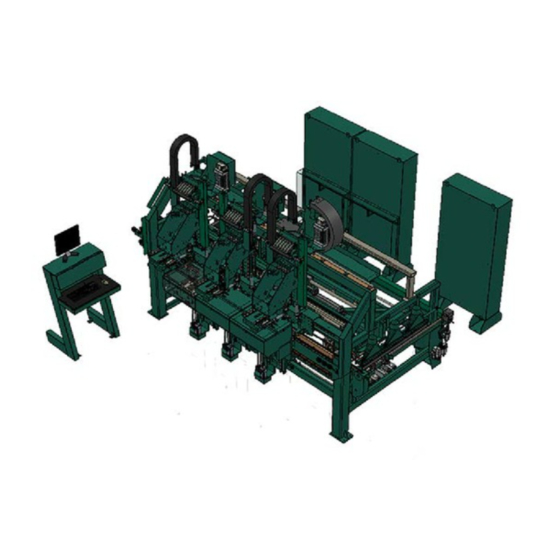
While the hinge process takes place a door lock and face plate is drilled. Feeding the door to the 990-H, is an ON-2012 config- ured as a feeder. On the output is an ON-2012 configured as a stacker. Figure 2- 1 below, shows... -
Page 25: 990-H Machine Tour
Operator’s Tour 990-H Machine Tour The 990-H can be paired with different feeder and stacker model numbers. This manual assumes the ON-2012 as a feeder and stacker. These machines are addressed in separate manuals. 990-H Door Hanger ON-2012 Stacker ON-2012 Feeder The 990-H Door Hanging System FIGURE 2- 2. - Page 26 • The door is automatically positioned while the operator loads and clamps the hinge jamb. Hinge Applicator Head Lock Back Section Operator Controls Feed System Hydraulic Tanks for Six Shooters Key Assemblies on the In-Feed Section FIGURE 2- 3. KVAL 990-H Operation Manual...
- Page 27 • Includes hinge attachment for three hinge butts on both door and jamb Six Shooter Hinge Router Head Valve Bank Hopper Screw Driver Drill Router Chisel Chisel Right Left Key Assemblies on the Front Section FIGURE 2- 4. KVAL 990-H Operation Manual...
- Page 28 • Works in partnership with front section process • Includes faceplate routing • Includes boring for lock and bolt. Hydraulic Main Air Supply Lock Bore Motor Tanks for Six Valve Shooters Key Assemblies on the Back Section FIGURE 2- 5. KVAL 990-H Operation Manual...
- Page 29 Operator’s Tour Out-Feed: • .The door is automatically positioned to be feed into stacker Dust Collection Blow -Off Feed Belts Key Assemblies on the Out-Feed Section FIGURE 2- 6. KVAL 990-H Operation Manual...
-
Page 30: About The Electrical Panels
Operator’s Tour About the Electrical Panels The 990-H has a Main Electrical Panel and a High Frequency Panel. Figure 2- 7 below, is an overview of the location of assemblies in the panels The High Frequency Panel The Main Electrical Panel: •... -
Page 31: Description Of The Six Light Panel
Operator’s Tour Description of the Six Light Panel The six lights on this panel indicate the status of the 990-H system. Refer to the “KVAL 990-H Service Manual” for information on using this panel Note: for troubleshooting. The Sequence that the lights activate is as follows:... -
Page 32: About Sensors
Operator’s Tour About Sensors On the 990-H, sensors provide input to the PLC as part of the automation of the door cutting pro- cess. It is important to keep the sensors cleaned and aligned to keep the door process running smoothly. -
Page 33: Quick Start
Quick Start Quick Start Ensure factory air is present at machine and the 990-H main air supply valve is turned on. Power up the 990-H.See “How to Power Up the 990-H” on page 2-13. Home the 990-H. See “Home the 990-H” on page 2-14. - Page 34 When the process is completed the door will feed out and a new door will feed in To continue processing another door go to step 7. 2-12 KVAL 990-H Operation Manual...
-
Page 35: Powering Operations For The 990-H
Powering Operations for the 990-H Powering Operations for the 990-H This section describe how to power up and to power down the 990-H. Powering up the system includes: • Applying power to the entire system • Starting the Control Circuit Powering down the system includes: •... -
Page 36: Home The 990-H
The 990-H must go through a homing routine before any operations are performed. The homing routine sets a zero reference from which the 990-H measures its movement and cutting process. If power is lost or the 990-H is re-set, the homing routine must be performed again to reset the zero reference... -
Page 37: Emergency Shutdown And Recovery
Shooters becoming “stuck” as they move into position, causing delay and potentially damaging the 990-H. During normal operation, remove each of the three red safety hooks from the Six-Shooter heads and place in the hanging storage spot above the in-feed end of the 990-H. 2-15 KVAL 990-H Operation Manual... -
Page 38: Description Of User Interface Screens
This section describes the user interface screens. The user interface allows the operator to use a touch screen to control the door cutting process, auto-run, manually run the door, store door pro- files, and use diagnostics to help troubleshoot the 990-H. Screen Selection Menu Map Below are the menu selections for the 990-H. -
Page 39: Machine Feed Back
Note: Use this information to isolate issues if having problems with the machine. Controlling Access to User Screens The 990-H has the ability to lock out changes to certain parameters such a presets and calibra- tions. Locked out parameters may vary due to customer design wants. -
Page 40: Main Screen
Description of User Interface Screens Main Screen The Main Screen is also the startup screen for the 990-H. From this screen, all the basic user inter- face controls are available to run a door. Main Screen FIGURE 2- 9. 2-18... - Page 41 This button stops the door in the process. Shut Down System Button This button shuts down the computer. Use this button as part of the shutdown pro- cess.See “How to Power Down the 990-H” on page 2-14 Preset Selection Button Group Pressing a preset button, calls one of twelve presets stored in mem- ory.
- Page 42 Backsection The settings include lock specifications for 3 lock settings, the ability to enable and disable lock bore, bolt drill, and face plate routing. indicates the backset distance for the each downloaded preset. Lock Backset 2-20 KVAL 990-H Operation Manual...
- Page 43 For manual operation, see “Width Adjust Group” on page 2-31 . Refresh File List Button The refresh button rescans the operating files for new code rou- tines that are added during updates or troubleshooting. 2-21 KVAL 990-H Operation Manual...
-
Page 44: Setup Screens
Pre-Drill Setup Main Cal Screen From this screen you can perform machine calibration, change machine timing and speeds. The screen addresses the back section (lock parameters) of the 990-H. Main Cal Setup Menu FIGURE 2- 10. 2-22... - Page 45 Disable the button to use the three stages. Enable the button to Single Step Single Step by pass the three stages and perform the bore with one single cut. 2-23 KVAL 990-H Operation Manual...
- Page 46 Longer times will allow the door to feed longer. Out feed Stop: This is the time, in seconds, between the period the door covers the “before-out feed eye” and when the door clamps. Longer times will allow the door to feed longer. 2-24 KVAL 990-H Operation Manual...
-
Page 47: Setup Hinges 1-3 Screens
From these screens you can adjust the parameters of each head. Refer to Figure 2- 1 on page 2- 2 for head locations. • adjusts left head. Setup Hinge 1 • adjusts center head. Setup Hinge 2 • adjusts right head. Setup Hinge 3 Hinge Setup Menu (1 of 3) FIGURE 2- 11. 2-25 KVAL 990-H Operation Manual... - Page 48 X, Y, and Z direction. Lower Right Chisel (X, X,Y,and Z): Adjustments here moves just the lower right chisel in the X, Y, and Z direction. 2-26 KVAL 990-H Operation Manual...
-
Page 49: Pre-Drill Screen
Setup Screens Pre-Drill Pre-Drill: Adjustments move the point-to-point drill in the X, Y, and Z direction 2-27 KVAL 990-H Operation Manual... -
Page 50: About The Pre-Drill Screen
Delrin. Mirror Image of Jamb Parameters Entered Positive Door Direction 'Y' Zero Point Positive Direction Negative Direction 'X' Zero Point Pre-Drill Screen Description FIGURE 2- 12. 2-28 KVAL 990-H Operation Manual... -
Page 51: Manual Operation
Manual Operation Manual Operation From this screen you can control certain functions of the machine in manual mode. Manual Screen FIGURE 2- 13. 2-29 KVAL 990-H Operation Manual... - Page 52 Test Mode runs the hinge cycle, but does not extend the tools. This is primarily used to verify a new template is correct and the hinge car- riage will not bump into the H-Block or other assemblies. 2-30 KVAL 990-H Operation Manual...
- Page 53 • Hoppers can be toggled on or off • Can clear the screws in the hopper system • Control the air supply to the hoppers • Enable or disable screw drop • Move Heads into position 2-31 KVAL 990-H Operation Manual...
-
Page 54: Diagnostic Screen
The top line will have the most current routine that is running. If the machine issue can not be resolved, call KVAL Inc. (1-800-553-5825). Have any error code that is displayed, ready to give the KVAL representa- tive. -
Page 55: Chapter 3 Calibration Of 990-H
CHAPTER 3 Calibration of 990-H This chapter describes the steps to calibrate the 990-H, Door Pre-Hanging Machine Chapter 3 at a Glance About Calibration .................... 3-2 Flow Chart of Calibration ................3-2 Before you Calibrate .................. 3-3 About the KVAL Calibration Routine ............. -
Page 56: About Calibration
The KVAL 990-H has a built in Calibration routine to cut a horizontal slot with known parame- ters. The routine allows you to make the cut, measure, observe any anomalies, and help isolate to the component that causes the problem. -
Page 57: Flow Chart Of Calibration
About Calibration Flow Chart of Calibration The flow chart below illustrates the steps in performing a calibration on the 990-H. Calibration Process Flowchart FIGURE 3- 1. KVAL 990-H Operation Manual... -
Page 58: About The Kval Calibration Routine
About the KVAL Calibration Routine About the KVAL Calibration Routine The calibration routine creates a reference cut to check settings against a “known good” source. The routine is used to verify the front section. It routes a horizontal slot and drills a center hole at precise specifications. -
Page 59: Calibration Slot Drilling Specifications
About the KVAL Calibration Routine Calibration Slot Drilling Specifications The calibration routine will route the following slot with the dimensions and positioning below Slot Position: Center of Door Edge Center Between H Block H Block Inside Slot: Pilot Hole: • Length = 20.00 mm + Diameter •... -
Page 60: Run The Calibration Routine
Choose door Length. Disable three of the hinges leaving one hinge enabled. Load the Door and Start the Cut Load the test door into the in-feed of the 990-H. Verify the setup and check for machine is safe to run. Press the button, to begin the process. -
Page 61: Check Specifications Of The Front Section
Sample of Adjustment Menu FIGURE3- 5. Note: KVAL suggests to follow the steps in the order below. Step 1 Verify and Adjust the Hinge Carriage Step 2 Verify and Adjust the Router Calibration Step 3 Verify and Adjust the Pre-Drill Calibration... -
Page 62: Step 1: Hinge Carriage Calibration
Exit out of the Setup screen and rerun the Calibration test. Re-measure the slot. If slot is not centered, repeat the steps above until the slot is centered. After centering is achieved, select to store the corrections. Combine with Base KVAL 990-H Operation Manual... - Page 63 Enter the offset in this box. Select the check mark to confirm this number and exit to go back to the Setup screen. Exit out of the Setup screen and rerun the Calibration test. Re-measure the parameters of slot. KVAL 990-H Operation Manual...
-
Page 64: Step 2: Router Calibration
• The width is the diameter of the bit. • The slot should be centered in the H-block and center on the thickness of the door. Adjusting the Router: Run the Calibration Routine. See “Run the Calibration Routine” on page 3-6. 3-10 KVAL 990-H Operation Manual... -
Page 65: Step 3: Pre-Drill Calibration
Run the Calibration Routine. See “Run the Calibration Routine” on page 3-6. Check, measure, and calculate specifications of Pre-Drill cut. To set a new reference, go to the calibration menu and select Combine with Base Enter calculations. 3-11 KVAL 990-H Operation Manual... -
Page 66: Step 4: Chisel Calibration
After the hinge run is finished, check all four corners of the hinge to see if the chis- els are in the correct location. If the corners of the hinge are out of specification, continue the process on the next page. 3-12 KVAL 990-H Operation Manual... - Page 67 Select the button to combine the two numbers to create refer- Combine with Base ence. 3-13 KVAL 990-H Operation Manual...
-
Page 68: Check Specifications Of The Back Section
Run a known good lock cut at a standard location on a Right Hand or Left Hand door. Once the lock cut is completed, check the distance from the top of the door to the center of the lock. Note the measurement value. Measure Reference Door Lock FIGURE 3- 11. 3-14 KVAL 990-H Operation Manual... -
Page 69: Strike Plate Calibration
Run a known good Strike Plate at a standard location on a Right Hand or Left Hand door. Once the lock cut is completed, check the distance from the top of the door to the center of the Strike Plate. Note the measurement value. Measure 3-15 KVAL 990-H Operation Manual... -
Page 70: Adjusting Fast Lock Plate Timing
This number is in seconds. If there is a delay before the vertical moves, enter a smaller number in this box. Fast Lock Plate Timing Menu FIGURE 3- 12. 3-16 KVAL 990-H Operation Manual... -
Page 71: Adjusting Slow Lock Plate-Timing
This number is in seconds. If there is a delay before the vertical moves, enter a smaller number in this box. Slow Lock Plate Timing Menu FIGURE 3- 13. 3-17 KVAL 990-H Operation Manual... - Page 72 Check Specifications of the Back Section 3-18 KVAL 990-H Operation Manual...
-
Page 73: Chapter 4 System It Administration
CHAPTER 4 System IT Administration This chapter describes the KVAL 990-H controller. The controller is an on board computer that supplies the user interface and controls the operation of the machine. With the controller, KVAL can remotely help troubleshoot your machine. - Page 74 Support will be able to access your machine through your company’s Intranet and help solve any issues that may occur. Connection to the Intranet is achieved by interfacing with the 990-H con- troller. The location of the Intranet connection is identified in the figure below (RJ45 to Intranet.) About the 990-H Computer ®...
- Page 75 About Remote Connection to KVAL Service Remote access is a powerful tool to help fix issues that occur with the 990-H machine. With the remote access, our KVAL service technician is able to observe your user screen in real time, read ®...
- Page 76 System IT Administration KVAL 990-H Operation Manual...
- Page 77 3-11 router slot dimensions description 2-24 router, steps to front section 3-10 slot dimensions key assemblies slow lock timing front section status 3-17 steps before feedback 2-17 strike plate 3-15 suggested order of steps KVAL 990-H Operation Manual...
- Page 78 2-11 jog hinge carriage key assemblies user interface description overload relay light description 2-30 LCD display plate routine timers smart power supply description 2-24 KVAL 558 Operation Manual...
- Page 79 2-16 method to use 2-15 Safety Sign Off Sheet 1-11 Safety Concerns voltage levels 1-14 sensors sensors 2-10 types 2-10 voltage levels location in high frequency panel 2-10 service connecting your machine to KVAL Service KVAL 990-H Operation Manual...
- Page 80 2-31 Windows CE® operating system,about X-axis calibration routine illustration of adjustment Y-axis calibration hinges illustration of calibration 3-10 zero-energy start-up clean up 1-10 inspect 1-10 KVAL 558 Operation Manual...
Need help?
Do you have a question about the 990-H and is the answer not in the manual?
Questions and answers