Advertisement
Quick Links
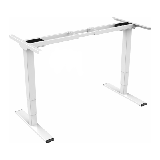
Item No.: SPE-226A
Installation guide
Technical data
Column Stage
3
Max. Weight Capacity
100KG
Height Range
645-1300mm(With tabletop)
Width Range
1100-1700mm
Component list
Qty No.
Qty
No.
Part
Part
1
2
2
2
Feet
Lifting Column
Qty No.
Qty
No.
Part
Part
3
2
4
2
Left
Connection rod
Supporting Beam
Qty No.
Qty
No.
Part
Part
5
2
6
2
Right
Supporting Beam
Side bracket
No.
Part
Qty No.
Part
Qty
1
7
8
1
Adapter arm
Adapter
Qty No.
Qty
No.
Part
Part
10
9
1
1
Handset
(Option)
Control Box
Qty No.
Qty
No.
Part
Part
11
1
12
1
Adapter cable
Power Plug
Accessory list
Attention: The drawings below are for guidance only and they may differ
slightly from the product and fittings received. Please contact our customer
service department if you have any queries.
Image
No.
Spec
A
M6
B
M6
C
M6
D
St4. 2
E
Cable tie
F
St4. 2
Allen Key
G
4x4mm
9
8
3
7
5
12
11
2
1
STEP 1
Install the supporting beam and the side bracket
A
x4
If the connecting rod cannot be inserted
into the supporting beam, please loosen
the screws on the beam.
G
4x4
3
5
Qty
4
Using screws (A) to connect the connection rod (3) with the left
8
supporting beam (4) and the right supporting beam (5), and
tighten them with the allen key (G).
8
6
STEP 2
Install the lifting column
6
B
16
x8
1
G
4x4
2
6
STEP 3
Install the feet
10
C
x8
G
4x4
1
2
Tighten it
4
G
A
6
Using screws (A) to connect the side bracket (6) with the left
supporting beam (4) and the right supporting beam (5), and
tighten them with the allen key (G).
G
B
5
4
Using screws (B) to connect the lifting column (2) with the left
supporting beam (4) and the right supporting beam (5), and
tighten them with the allen key (G).
G
C
Connect the feet(1) and the lifting column (2) with screws (C),
and tighten them with the allen key (G).
4
5
Advertisement

Related Manuals for Spacetronik SPE-226A


Summary of Contents for Spacetronik SPE-226A
- Page 1 STEP 1 Install the supporting beam and the side bracket Item No.: SPE-226A Tighten it Installation guide If the connecting rod cannot be inserted into the supporting beam, please loosen the screws on the beam. Accessory list Attention: The drawings below are for guidance only and they may differ slightly from the product and fittings received.
- Page 2 Loosen STEP 4 Install the adapter arm The expansion of supporting beam cannot exceed this hole. Attention Common fault treatment 1. Power supply: AC100V-240V,50/60Hz 2. Service Environment: 0-40℃ 3. Unplug the power plug before cleaning, wipe the dust on surface with slight wet dishcloth when cleaning, be careful not to let the drops into the internal parts, not loose Fault phenomenon Method...
Need help?
Do you have a question about the SPE-226A and is the answer not in the manual?
Questions and answers