Sign In
Upload
Manuals
Brands
Phoenix Contact Manuals
Controller
AXC F XT SPLC 1000
User Manuals: Phoenix Contact AXC F XT SPLC 1000 Module
Manuals and User Guides for Phoenix Contact AXC F XT SPLC 1000 Module. We have
1
Phoenix Contact AXC F XT SPLC 1000 Module manual available for free PDF download: User Manual
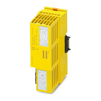
Phoenix Contact AXC F XT SPLC 1000 User Manual (202 pages)
left-alignable safety-related controller
Brand:
Phoenix Contact
| Category:
Controller
| Size: 7 MB
Table of Contents
Section 1
3
Table of Contents
3
For Your Safety
9
Identification of Warning Notes
9
Qualification of Users
9
Information about this User Manual
9
Purpose of this User Manual
9
Validity of the User Manual
10
Information on Open Source Software Licenses and Requesting Source Code
10
General Safety Notes
11
Field of Application of the Product
13
Intended Use
13
Note on Security
14
Product Changes
14
Foreseeable Misuse
14
Safety Notes
15
Electrical Safety
16
Safety of the Machine or System
17
Standards and Directives
18
Documentation
18
System Requirements (Hardware and Software)
20
Abbreviations Used
21
Safety Hotline
22
Transport, Storage, and Unpacking
23
Transport
23
Storage
23
Unpacking
23
General Description of the SPLC 1000
25
Description of the AXC F XT SPLC 1000
25
Description of the Safety-Related Functioning of the SPLC 1000
27
Calculating/Determining the Response Time (Safety Function Response Time, SFRT)
31
Determining SFRT F_Wd_Time out
32
F_Wd_Time out Max
32
Max
32
And F_Wd_Time in
32
Determining F_Wd_Time in Min /F_Wd_Time out Min
35
Can be Implemented
44
Possible Fields of Application of the SPLC 1000
45
SPLC 1000 Components
45
Connection and Operating Elements
45
SPLC 1000 Printing and Test Mark
46
Diagnostic and Status Indicators
47
Internal Basic Circuit Diagram
50
Mounting Hardware
51
Safety Notes
51
Basic Information
52
Recommended End Brackets
52
Structure of an Axioline F Station
54
Mounting the SPLC 1000
55
Removing the Plcnext Control Supply Connector
56
Removing Other Connectors from the Plcnext Control
57
Unlatching Electronics Modules
57
Mounting the Bus Base Modules
58
Snapping on Electronics Modules
60
Connecting Connectors to the Plcnext Control Device
60
Connecting the Supply Connector
60
Connecting and Wiring the Hardware
61
Sizing of the Power Supply
61
DC Distribution Network According to IEC 61326-3-1
63
Connecting the Supply Voltage
63
Supply Voltage
63
Supply Connector: Terminal Point Assignment
64
Supply Connector: Assembling and Connecting Cables
64
Feed-In of the Supply Voltage
64
Connecting the Supply Connector
65
Commissioning and Validation
67
Initial Commissioning
68
Steps for Initial Commissioning of the SPLC 1000
68
Recommissioning after Replacing the SPLC 1000
70
Recommissioning after Replacing the Plcnext Control with the Use of a New SD Card that Contains a Safety-Related and a Non-Safety-Related Project
71
Recommissioning after Replacing the Plcnext Control with the Use of a New, Empty SD Card
71
Recommissioning after Replacing the Plcnext Control Without the Use of an SD Card
71
Recommissioning after Replacing the Plcnext Control
71
Example SPLC 1000 Commissioning
72
Example: the SPLC 1000 as the F-Host for Axioline F and Axioline Smart Elements F-Devices
72
Further Example Configurations
73
Integration of the SPLC 1000 as the F-Host in Plcnext Engineer
76
Software Requirements
77
Plcnext Engineer Software
77
Installing Plcnext Engineer
77
Plcnext Engineer License
77
User Interface
78
Creating a New Project
80
Defining a Project Password
81
Figure 6-8 IP Address Range Set in the Project
82
Figure 6-9 Controller IP Address Set
82
Further Actions/Steps in the Plcnext Engineer Software
82
Setting the IP Address of the Controller in the Project
82
Creating the IP Address Range in the Project
82
Connecting Plcnext Engineer to the Controller
83
User Authentication
83
Figure 6-10 Configured Controller Assigned to an Online Device
83
Figure 6-11 "SECURE DEVICE LOGIN" Dialog
83
Figure 6-12 Controller Successfully Connected
83
Configuring PROFINET Devices
84
Adding PROFINET Devices
84
Figure 6-13 Role Picker for Selecting PROFINET Devices
84
Figure 6-14 PROFINET Devices in the "PLANT" Area and in the Device List
85
Figure 6-15: Role Picker for Selecting the I/O Modules
86
Adding I/O Modules (F-Devices)
86
Figure 6-16: Entering the Project Password
87
Figure 6-17: Successful Login to the Safety-Related Area
87
Figure 6-18: I/O Modules Connected to the PROFINET Device
87
Figure 6-19: Role Picker for Selecting the I/O Modules
88
Figure 6-20: Role Picker for Selecting the I/O Modules
88
Figure 6-21 Example Project
89
Programming in Accordance with IEC 61131-3 - Non-Safety-Related Example Program
90
Creating a POU
90
Figure 6-22: "Add Program" Program POU Context Menu
90
Instantiating Programs
91
Figure 6-23: Program Pous: Main and S_Main
91
Figure 6-24 Tasks and Program Instances in the "Tasks and Events" Editor
92
Programming in Accordance with IEC 61131-3 - Safety-Related Example Program
93
Assigning/Checking the Profisafe Address (F-Address) of Profisafe Devices
93
Figure 6-25: F-Address of the F-Host: F_Source_Add (F_Source_Address)
93
Checking/Setting Safety Parameters for Configured F-Devices
95
Figure 6-27 "Safety Parameters" Editor: AXL F PSDO8/3 1F
95
Figure 6-28 "Safety Parameters" Editor: AXL SE PSDO4/2 2A
96
Figure 6-29: "Safety Parameters" Editor: AXL SE PSDI8/3
97
Safety-Related Parameters in the Example
97
Management/Diagnostic Variables for F-Devices
98
Figure 6-30 Management/Diagnostic Variables for each Configured F-Device
98
Figure 6-31 Management/Diagnostic Variables for All Configured F-Devices
99
Figure 6-32 Management/Diagnostic Variables of F-Devices (Default)
100
Figure 6-33 Exchange Variables in the Example
101
Creating Variables (Exchange Variables)
101
Figure 6-34 "Add Variable (Safety PLC)" Context Menu
102
Figure 6-35 Setting the Data Direction
102
Opening a Safety-Related POU
103
Creating Safety-Related Variables
104
Figure 6-36: Creating Variables for a POU (in the Example: for the "S_Main" POU)
104
Input/Output Variables in the Example
104
Figure 6-37 Selecting Diagnostic/Management Variables
105
Creating a Safety-Related Program
106
Figure 6-38 Safety-Related Example Program with Errors Displayed
107
Figure 6-39 Error List
107
Assigning Safety-Related Process Data
108
Figure 6-40 Assigning Safety-Related Process Data
108
Figure 6-42 Safety-Related Program Without Errors
109
Figure 6-41 Safety-Related Variables: Process Data Assigned
109
Transferring Projects to the Plcnext Control Device and SPLC 1000 and Displaying Online Values
110
Transferring a Non-Safety-Related Project to the Plcnext Control
110
Transferring a Safety-Related Project to the SPLC 1000 (Specifying a Controller Password if Necessary)
112
Displaying Safety-Related Online Values
115
Plcnext Engineer - Debug Mode
117
Operator Acknowledge
118
Errors: Diagnostics, Messages, and Removal
121
Diagnostics for F-Devices
121
Diagnostics for SPLC 1000
121
Possible Errors
122
Errors and Error Codes of the SPLC 1000 as the F-Host
124
Errors Codes of the SPLC 1000 as the F-Host
124
Errors and Error Codes of the SPLC 1000 as an F-Device
130
Errors Codes of the SPLC 1000 as an F-Device
130
Evaluation and Acknowledgment of Module-Specific Diagnostic Messages
131
Asyncom_Pn_1 Function Block
131
Pnfd_Axl_Diag_2 Function Block
132
System Variables and Status Information
133
General Information
133
Data Structures
133
System Variables of the SPLC 1000
135
SPLC System Variable
135
SPLC System Variable and Elements of the SPNSV2_TYPE
135
Diagnostic Status Register of the SPLC 1000
135
Splc.diag.status_Reg.XXX Diagnostic Status Register
137
Splc.diag.status_Reg
137
SPLC_PROFISAFE_DIAG System Variable and Elements of the PROFISAFE_DIAG_OUT Structure
141
SPLC_PROFISAFE_DIAG System Variable
141
System Variables
142
Data Structure
142
SPLC_CONTROL_COMMAND System Variable and Elements of
142
SPLC_CONTROL_CONFIRM System Variable and Elements of
142
Fdev_Inx and Fdev_Outx (X = 0
143
Management/Diagnostic Variables for each Configured F-Device
144
Global Management/Diagnostic Variables for F-Devices
147
Management/Diagnostic Variables for F-Devices
147
Management/Diagnostic Variables of the SPLC 1000 as an F-Device
149
Profisafe: Device Diagnostics Variables (Local Device)
149
PLC_CRC_PRJ System Variable
152
Profisafe: Collective Diagnostics Variables (Local Device)
152
Removing Hardware
153
Safety Notes
153
Removing Cables
154
Removing the Connector
154
Unlatching the SPLC 1000
155
Removing the Bus Base Module
155
10 Device Replacement, Device Defects, and Repairs
157
Device Replacement
157
Device Defect and Repair
158
11 Maintenance, Decommissioning, and Disposal
159
Maintenance
159
Decommissioning and Disposal
159
Extended SPLC 1000 Settings and Further Useful Information
161
Startup Parameterization of PROFINET Devices
161
Function Block for Managing PROFINET Application Relationships (AR)
163
Substitute Value Behavior for PROFINET Devices and Profisafe F-Devices
164
13 Technical Data and Ordering Data
165
Ordering Data
165
Extension Module
165
Controller
165
Modules
165
Accessories
166
Software
166
Documentation
166
Technical Data
168
A Appendix: Terms for Profisafe
173
B Appendix: Checklists
175
Planning
176
B 1 System-Specific Checklists
176
B 1.2 Programming
178
B 1.3 Commissioning
179
B 1.4 Validation
180
B 2 Device-Specific Checklists
182
Planning
182
B 2.2 Assembly and Electrical Installation
183
B 2.3 Commissioning and Parameterization
184
B 2.4 "Initial Commissioning" and "Recommissioning/Device Replacement" Validation
185
C Appendix For Document Lists
187
List of Figures
187
Section 2
189
C 2 List of Tables Section 1 Section 2
193
List of Tables
193
Index
195
D Appendix: Revision History
197
Advertisement
Advertisement
Related Products
Phoenix Contact SCK-M-I-8S-20A
Phoenix Contact SCK-M-U-1500V
Phoenix Contact SCX 2POE 2LX
Phoenix Contact SCX 4POE 2T
Phoenix Contact CHARX SEC-3150
Phoenix Contact CHARX SEC-3050
Phoenix Contact SOL-SC-WTH-STN
Phoenix Contact Axioline Smart Element AXL SE AO4 U 0-10
Phoenix Contact Axioline F SBT V3
Phoenix Contact FL NAT SMN 8TX-M
Phoenix Contact Categories
Controller
Control Unit
Switch
Power Supply
Media Converter
More Phoenix Contact Manuals
Login
Sign In
OR
Sign in with Facebook
Sign in with Google
Upload manual
Upload from disk
Upload from URL