
Subscribe to Our Youtube Channel
Related Manuals for Lattice Semiconductor MachXO2-1200ZE


Summary of Contents for Lattice Semiconductor MachXO2-1200ZE
- Page 1 MachXO2-1200ZE Breakout Board Evaluation Kit User’s Guide January 2012 Revision: EB68_01.1...
- Page 2 Features The MachXO2-1200ZE Breakout Board Evaluation Kit includes: • MachXO2-1200ZE Breakout Board – The board is a 3” x 3” form factor that features the following on-board components and circuits: – MachXO2-1200ZE PLD (LCMXO2-1200ZE-1TG144C) –...
-
Page 3: Storage And Handling
• FTDI Chip USB hardware drivers (installed as an option within the Diamond installation program) MachXO2-1200ZE Device This board features the MachXO2-1200ZE PLD which offers embedded Flash technology for instant-on, non-vola- tile operation in a single chip. Numerous system functions are included, such as a PLL and 64Kbits of embedded RAM plus hardened implementations of I C, SPI, timer/counter, and user Flash memory. -
Page 4: Demonstration Design
Sheet. Demonstration Design Lattice provides a simple, pre-programmed demo to illustrate basic operation of the MachXO2-1200ZE device. The design integrates an up-counter with the on-chip oscillator. Note: You may obtain your Breakout Board after it has been reprogrammed. To restore the factory default demo... -
Page 5: Download Demo Designs
Programming a Demo Design with the Lattice Diamond Programmer The demonstration design is pre-programmed into the MachXO2-1200ZE Breakout Board by Lattice. If you have changed the design but now want to restore the Breakout Board to factory settings, use the procedure described below. - Page 6 This section describes the features of the MachXO2-1200ZE Breakout Board in detail. Overview The Breakout Board is a complete development platform for the MachXO2-1200ZE PLD. The board includes a pro- totyping area, a USB program/power port, an LED array, and header landings with electrical connections to most of the PLD’s programmable I/O, power, and JTAG pins.
- Page 7 This section describes the principle sub systems for the Breakout Board in alphabetical order. Clock Sources All clocks for the counter demonstration designs originate from the MachXO2-1200ZE PLD on-chip oscillator. You may use an expansion header landing to drive a PLD input with an external clock source.
- Page 8 MachXO2-1200ZE Breakout Board Lattice Semiconductor Evaluation Kit User’s Guide Table 3. Expansion Header Pin Information (J2) Pin Number Function MachXO2-1200ZE Pin VCCIO0 118, 123, 135 PT17D/DONE PT17C/INITn PT17B PT17A PT16D PT16C PT16B PT16A PT15D/PROGn PT15C/JTAGen PT15B PT15A PT12D/SDA/PCLKC0_0 PT12C/SCL/PCLKT0_0 PT12B/PCLKC0_1...
- Page 9 MachXO2-1200ZE Breakout Board Lattice Semiconductor Evaluation Kit User’s Guide Table 4. Expansion Header Pin Information (J3) Pin Number Function MachXO2-1200ZE Pin VCC_1.2V 36, 72, 108, 144 VCCIO1 79, 88, 102 VCC_1.2V 36, 72, 108, 144 PR10C PR10D PR10A PR10B PR9C...
- Page 10 MachXO2-1200ZE Breakout Board Lattice Semiconductor Evaluation Kit User’s Guide Table 5. Expansion Header Pin Information (J4) Pin Number Function MachXO2-1200ZE Pin VCC_3.3V VCCIO3 7, 16, 30 VCC_3.3V PL2A/L_GPLLT_FB PL2B/L_GPPLC_FB PL2C/L_GPLLT_IN PL2D/L_GPLLC_IN PL3A/PCLKT3_2 PL3B/PCLKC3_2 PL3C PL3D PL4A PL4B PL4C PL4D PL5A/PCLKT3_1...
- Page 11 MachXO2-1200ZE Breakout Board Lattice Semiconductor Evaluation Kit User’s Guide Table 6. Expansion Header Pin Information (J5) Pin Number Function MachXO2-1200ZE Pin VCCIO2 37, 51, 66 SI/SISPI/PB20D PB20B SN/PB20C PB20A PB18D PB18B PB18C PB18A PB15D PB15B PB15C PB15A PCLKC2_1/PB11B PB11D PCLKT2_1/PB11A...
- Page 12 MachXO2-1200ZE Breakout Board Lattice Semiconductor Evaluation Kit User’s Guide Figure 4. J2/J4 Header Landing Callout Top Side Figure 5. J3/J5 Header Landing Callout Top Side...
- Page 13 LED5 LED4 LED3 LED2 LED1 LED0 MachXO2-1200ZE PLD The MachXO2-1200ZE-1TG144C is a 144-pin TQFP package PLD device which provides 108 I/Os in a 20 x 20mm package. Table 7. MachXO PLD Interface Reference Item Description Reference Designators Part Number LCMXO2-1200ZE-1TG144C...
- Page 14 The USB mini-B socket of the Breakout Board serves as the programming and debug interface. JTAG Programming: For JTAG programming, a preprogrammed USB PHY peripheral controller is provided on the Breakout Board to serve as the programming interface to the MachXO2-1200ZE PLD. Programming requires the Lattice Diamond or ispVM System software.
-
Page 15: Troubleshooting
MachXO2-1200ZE Breakout Board Lattice Semiconductor Evaluation Kit User’s Guide Board Modifications This section describes modifications to the board to change or add functionality. Bypassing the USB Programming Interface The USB programming interface circuit (USB Programming and Debug Interface section) may be optionally bypassed by removing the 0 ohm resistors: R5, R6, R7, R8 (See Appendix A. -
Page 16: Ordering Information
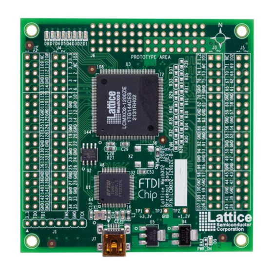
Figure “MachXO2-1200ZE Breakout Board, Top Side” updated with revi- sion B board photo. © 2012 Lattice Semiconductor Corp. All Lattice trademarks, registered trademarks, patents, and disclaimers are as listed at www.latticesemi.com/legal. All other brand or product names are trademarks or registered trademarks of...
Need help?
Do you have a question about the MachXO2-1200ZE and is the answer not in the manual?
Questions and answers