Advertisement
ASSEMBLY, INSTALLATION, CARE, MAINTENANCE AND USER INSTRUCTIONS
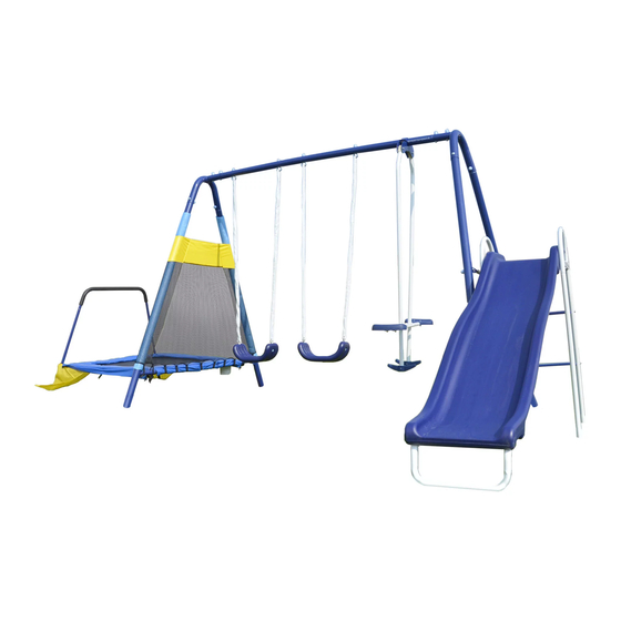
This product is designed to be used simultaneously by up to 6 children between ages 3 to 8.
Maximum weight of each user is 100lbs(45kg). Combined weight of all users must not exceed
600lbs(272kg).
Carefully read this entire instruction manual before you start to assemble or use this swing set.
You must follow all instructions and warnings while using this equipment.
Do not use this swing set on hard packed soil, concrete, or any kind of hard surface.
This equipment must be anchored (anchors not included). You should consult your local contractor
regarding the best way to anchor the product in your location of installation.
Assembly requires at least two adults.
For Customer Service, please call 1-866-370-2131 or visit
Flat M, Kaiser Estate Phase 3, 11 Hok Yuen Street, Hunghom, Kowloon, Hong Kong
MODEL#MSC-3242-6FT
Almansor Metal Swing Set
OWNER'S MANUAL
FOR RESIDENTIAL USE ONLY
Monday – Friday 9:00 AM – 5:00 PM Eastern Time
Sportspower Ltd.
Corporate Office 1-800-497-6106
WARNING
1
www.sportspowerltd.net
Advertisement

Subscribe to Our Youtube Channel
Related Manuals for SPORTSPOWER Almansor MSC-3242-6FT


Summary of Contents for SPORTSPOWER Almansor MSC-3242-6FT
- Page 1 Assembly requires at least two adults. For Customer Service, please call 1-866-370-2131 or visit www.sportspowerltd.net Monday – Friday 9:00 AM – 5:00 PM Eastern Time Sportspower Ltd. Flat M, Kaiser Estate Phase 3, 11 Hok Yuen Street, Hunghom, Kowloon, Hong Kong Corporate Office 1-800-497-6106 1 ...
- Page 2 INTRODUCTION Dear Valued Customer, Congratulations on your Sportspower play set purchase! Please read and completely understand the contents of this owner’s manual. This manual contains specific instructions and warnings that must be followed to prevent injuries. This play set is for residential use only. This play set is NOT intended for public or commercial use.
-
Page 3: Table Of Contents
TABLE OF CONTENTS IMPORTANT INSTRUCTIONS AND WARNINGS ...................... 4 IMPORTANT CONSUMER INFORMATION SHEET ...................... 8 ANCHORING .................................. 9 CARE AND MAINTENANCE CHECKLIST ........................ 1 1 TOOLS NEEDED ................................ 1 2 PARTS LIST .................................. 1 3 ASSEMBLY AND INSTALLATION INSTRUCTIONS ... -
Page 4: Important Instructions And Warnings
IMPORTANT INSTRUCTIONS AND WARNINGS WARNING READ ALL INSTRUCTIONS BEFORE ASSEMBLING OR USING THIS EQUIPMENT AGE LIMIT This product is designed to be used by up to six (6) children between the ages of 3 to 8. Maximum user weight is 100 pounds (45kg) each with a combined maximum weight of 600 pounds (272kg). ... - Page 5 Some consumers want an anchoring system that allows the product to be moved to different locations. Other consumers want to keep their swing set in a permanent location. There are different types and different methods of anchoring this product. Sportspower does not make a specific anchoring recommendation as each consumer’s need and conditions can vary.
- Page 6 ALWAYS return safely to the ground before approaching another play area. DO NOT allow children to climb on structural parts (e.g. legs, top bar). These are structural components and are not designed for play. ALWAYS check the slide or other parts exposed to the body for extreme heat from the sun before allowing children to use the equipment.
- Page 7 Supervisor’s or owner’s role in preventing injuries It is the responsibility of the supervisor(s) of the trampoline users to provide knowledgeable and mature supervision. They need to know and enforce all the rules and warnings set forth in this manual in order to minimize the likelihood of accidents and injuries and to inform users of these rules.
-
Page 8: Important Consumer Information Sheet
IMPORTANT CONSUMER INFORMATION SHEET The Consumer Product Safety Commission estimates there are more than 200,000 playground related injuries involving children each year. Injuries involving this hazard pattern tend to be among the most serious of all playground injuries and have the potential to be fatal, particularly when the injury is to the head. The surface under and around playground equipment can be a major factor in determining the injury-causing potential of a fall. -
Page 9: Anchoring
ANCHORING (NOTE:ANCHORS ARE NOT INCLUDED - MUST BE PURCHASED SEPARATELY) There are different ways of anchoring the equipment, depending on the type of ground on which the equipment is to be installed. Make sure that all anchors are below ground level to prevent tripping. You should consult your local contractor to decide the most appropriate way to anchor the equipment in your location. - Page 10 FRAME 12-5/8” CONCRETE 5” 2” BRICK OR GRAVEL Note: The maximum fall height for this product is 6 feet. The minimum ground clearance between the bottom of the suspended plays and the playing or ground surface must be 8 inches. ...
-
Page 11: Care And Maintenance Checklist
CARE AND MAINTENANCE CHECKLIST AT THE BEGINNING OF EACH PLAY SEASON: Tighten all hardware. Lubricate all metallic moving parts per manufacturer’s instructions. Check all protective coverings on bolts, pipes, edges, and corners. Replace if they are loose, cracked, or missing. -
Page 12: Tools Needed
TOOLS NEEDED Please prepare the following tools prior to assembling this equipment. TOOLS INCLUDED: Special Socket Wrench Big Allen Wrench Spring Loading Tool Wrench TOOLS NOT INCLUDED: Tape Measure Flat and Philips Head Screwdriver Hammer Wrench Small Allen Wrench 12 ... -
Page 13: Parts List
Parts list for main Frame assembly SIDE TOP BAR 2pcs TOP BAR LEG WITH FOAM 2pcs 2pcs CROSS BAR (WITH TWO HOLES) Hardware used for main frame assembly BOLT 5/16”*2.5” (8MM*63MM) 8pcs BOLT 5/16”*2.5” (8MM*68MM) 2pcs NYLON NUT 5/16’’ 10pcs PLASTIC CAP (WITH ARC WASHER) 10pcs... - Page 14 Part list for trampoline assembly PROTECTIVE NET JUMP MAT FRAME PAD T4A-N L-SHAPED TUBE (LEFT) T4B-N L-SHAPED TUBE (RIGHT) T5-N STRAIGHT TUBE T6-N HANDLE BAR WITH FOAM T7A-N HANDLE BAR BASE TUBE(LEFT) T7B-N HANDLE BAR BASE TUBE(RIGHT) SUPPORTING TUBE SPRINGS 28pcs Hardware used for trampoline assembly...
- Page 15 Bracket used for glide ride assembly BRACKET BRACKET CLAMP REINFORCING STEEL SPACER 2pcs BOLT 5/16”x1” (8MM*25MM) 2pcs NYLON NUT 5/16’’ 2pcs Part list for glide ride assembly L1-N TOP SECTION HANGER 2pcs L2-N GLIDE SEAT SUPPORT 2pcs TUBE CAP(PRE-ASSEMBLED) 2pcs SMALL NYLON BEARING 2pcs...
- Page 16 Hardware used for glide ride assembly BOLT 1/4”x1.5” (6.5MMx37MM) 4pcs BOLT 1/4’’x1.7” (6.5MMx43MM) 2pcs SCREW 0.22”x3/4” (5.5MMx19MM) 4pcs J-BOLT 2pcs SPRING WASHER (MEDIUM) 4pcs CAP BOLT 1/4”x5/10” 2pcs (6.5MMx14MM) CAP NUT 1/4” 4pcs NUT 1/4” 2pcs SPRING WASHER (LARGE) 2pcs SPRING WASHER (MEDIUM) 4pcs...
- Page 17 Part list for slide assembly X1-N SLIDE SUPPORT (WITH OPENING) X2-N SLIDE SUPPORT X3-N SLIDE LEG TUBE X4-N SLIDE TOP SUPPORT BAR X5-N SLIDE FRONT SUPPORT SLIDE LADDER STEPS SLIDE Hardware used for slide assembly PLASTIC CONNECTOR BOLT 1/4” x 38mm ...
- Page 18 ASSEMBLY INSTRUCTIONS Place the playground equipment on level ground and not less than 6ft (1.8m) from any structure or obstruction such as a fence, garage, house, overhanging branches, laundry line or electrical wires. Do not install the playground equipment over concrete, asphalt, packed earth or any other hard surface.
-
Page 19: Assembly And Installation Instructions
ASSEMBLY AND INSTALLATION INSTRUCTIONS REFERENCE FOR LOCATION OF INSTALLATION STEP 1 – Assemble the top bar frame of the swing set Connect A1 to the two ends of A2 and secure with B1, B5, B4 and B3 as shown in FIGURE 1. Note: All round holes should be facing up and concave holes facing down. - Page 20 REFERENCE FOR LOCATION OF INSTALLATION Step 2 – Assemble the side of swing set with trampoline attachment Insert small end of A3 into the sleeves of T1. Connect Leg with Foam (A3) to A1 using B1, B5, B4 and B3 as shown in the FIGURE 2. FIGURE 2 20 ...
- Page 21 REFERENCE FOR LOCATION OF INSTALLATION STEP 3 Attach Legs (A4) to Top Bar (A1) using B1, B5, B4 and B3 as shown in the enlarged diagram in all places circled in the DIAGRAM A. Attach Cross Bar (A5) to Legs (A4) using B2, B6, B4 and B3 as shown in the FIGURE 3. IMPORTANT NOTE: The 2 holes on A5 will be used for connection to the slide in later steps.
- Page 22 STEP 4 – Attach the trampoline frame to the swing set Insert the ends of T8 into the sockets of A3. Align the holes and secure using T15, T19, T18 and T13 as shown. Connect T4A-N, T4B-N and T5-N using T16, T19, T18 and T13 and insert the ends of T4A-N and T4B-N into the sockets of T8 as shown in the FIGURE 4.
- Page 23 STEP 5 – Attach the trampoline frame to the swing set Align the holes on the trampoline frame legs (T7A-N and T7B-N) to the welding brackets on the corner of the assembled trampoline frame. Secure the top hole using T10 (which is longer than T11), T12 and T14.
- Page 24 STEP 6 - Attach the jump mat IMPORTANT: Make sure to wear heavy duty gloves to protect your hands from pinching and goggles to protect the eyes from injuries during installation of the springs. Lay out T2 (Jump mat) in the center of the frame and install spring (T9) to the four corners as shown in DIAGRAM A.
- Page 25 Continue to install all remaining springs in the same manner until the mat is full installed as shown in FIGURE 6. ENLARGED DIAGRAM FIGURE 6 25 ...
- Page 26 STEP 7- Attach the frame pad Pull the Frame Pad (T3) through the trampoline legs and fully cover all springs and trampoline frame. IMPORTANT: Make sure all metal parts are covered to avoid injuries from body contact. ENLARGED DIAGRAM FIGURE 7 26 ...
- Page 27 STEP 8-Attach the handle bar with foam to trampoline frame legs Connect Handle Bar with Foam (T6-N) to T7A-N and T7B-N. Align holes and secure using T17 and T20. FIGURE 8 27 ...
- Page 28 STEP 9-Secure the jump pad to the swing set Pull the hook with elastic band (stitched onto T1) under T8 and attach it to the triangle ring beneath the pad as shown. Tie all the straps sewn on T1 around T8 as shown in FIGURE 9. FIGURE 9 28 ...
- Page 29 STEP 10-Secure the jump pad to the frame Loop the straps located beneath the jump pad through the nearest triangle rings and securely tie a bow knot as shown. Make sure all straps are securely fastened and the jump pad is fully covering all metal parts.
- Page 30 Swing Seat Assembly STEP 11 Insert Eye Bolt for Swing Chain (J3) into the holes on A2 and secure with J6 and J8 as shown in DIAGRAM A. Attach Swing Seat (K1) to J3 using J7, J9 and J6 as shown in DIAGRAM B. DIAGRAM A DIAGRAM B ...
- Page 31 Glide Ride Assembly STEP 12 Attach L4 and L3 to A2 using N3R, L5 and N7 as shown in FIGURE 12. Use special socket wrench and screwdriver to tighten N3R and N7. Use special socket wrench and screw driver to tighten N7. FIGURE 12 31 ...
- Page 32 STEP 13 Insert L1-N (straight end) into M5 and secure with N4 and N12 on both sides. Attach M1 to the top of L1-N (curved end). Align holes and insert M2 as shown in DIAGRAM A. Attach L1-N to L3 on both sides and secure with N2R and N10 as shown in DIAGRAM B. DIAGRAM A DIAGRAM B ...
- Page 33 STEP 14 Attach L2-N to L1-N on both sides and secure with N5, M3, N11 and N8 as shown in FIGURE Concave holes face up Round holes face down FIGURE 14 33 ...
- Page 34 STEP 15 Attach M4 to L2-N and secure with N1, N6 and N9 as shown in FIGURE 15. FIGURE 15 34 ...
- Page 35 Slide Assembly STEP 16-Slide Assembly Insert Slide Front Support (X5-N) into Slide (Y2) and secure with Z9 and Z6. Connect (X4-N) into Slide (Y2) as shown in FIGURE 16. Bolt holes face up FIGURE 16 35 ...
- Page 36 STEP 17-Slide Assembly (continued) Connect Slide Ladder Steps (X6) to Slide Supports (X1-N and X2-N). Secure both sides using Z8, Z6 and Z4 as shown in FIGURE 17. Insert Slide Leg Tube (X3-N) into X1-N and X2-N as shown. Align the holes and hold in position.
- Page 37 STEP 18-Slide assembly (continued) Secure X4-N to the ladder using Z1, Z3, Z6 and Z5 as shown in DIAGRAM A. Place Slide (Y2) onto the assembled step ladder and secure both sides to the leg tubes using Z2, Z6, Z6 and Z4 as shown in DIAGRAM B.
- Page 38 STEP 19-Connect the slide to the swing set Connect the assembled slide to the swing set frame. Place Plastic Connector (Y1) between A5 and X1-N and secure together using Z7, Z6, Z3 and Z5 as shown in FIGURE 19. X1‐N FIGURE 19 38 ...
- Page 39 Congratulations! You have now completed installing the equipment. Please make sure to go back and check all hardware and ensure all bolts and nuts are securely tightened before using the playground equipment. Warning: Do not let children use the playground equipment until it is properly assembled and anchored.
-
Page 40: Manufacturer's Limited Warranty
MANUFACTURER’S LIMITED WARRANTY Sportspower Ltd warrants its products to be free from defects in material and workmanship under normal use and service conditions for ninety (90) days after the date of purchase. Extended warranty from 90 to 180 days will be offered to those customers registering their products at www.sportspowerltd.net...
Need help?
Do you have a question about the Almansor MSC-3242-6FT and is the answer not in the manual?
Questions and answers
How do I shorten the chains on the swing to make taller?
The manual does not provide specific instructions for shortening the swing chains. However, to make the swing taller, you can adjust the chain length by securely reattaching the chain to a higher link using an appropriate fastener, such as an S-hook or quick link. Ensure the modification maintains safety and stability. Always check that the swing maintains at least 8 inches of ground clearance.
This answer is automatically generated