Table of Contents
Advertisement
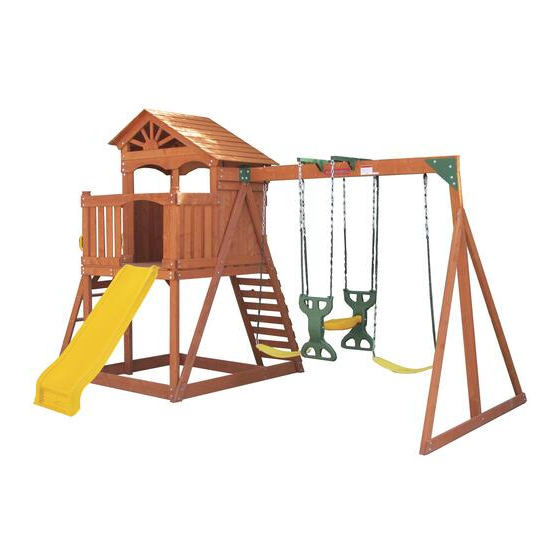
CEDAR RIDGE SWING SET
ASSEMBLY, INSTALLATION, CARE, MAINTENANCE AND USE INSTRUCTIONS
➢
This product is intended for use by children from ages 3 to 10.
➢
This unit is designed for use by up to 8 children at one time. Maximum weight of each user is 100
lbs.(45kg), with combined weight not to exceed 800 lbs.(360kg)
➢
Assembly requires at least three adults.
➢
Do not allow more than one child to play on the individual swing/slide at a time.
➢
Always inspect product thoroughly before each use.
PLEASE RETAIN THESE INSTRUCTIONS FOR FUTURE REFERENCE
For customer service, please call 1-866-370-2131 Monday-Friday 9am-5pm Eastern Time
Level 20, Parkview Centre, 7 Lau Li Street, Causeway Bay, Hong Kong
MODEL # WP-505A
OWNER'S MANUAL
FOR RESIDENTIAL USE ONL Y
!
DO NOT RETURN TO THE STORE
DO NOT RETURN TO THE STORE
or visit our website at www.sportspowerltd.net
SPORTSPOWER LTD
US Toll Free Number 1-800-497-610
WARNING
6
Advertisement
Table of Contents

Related Manuals for SPORTSPOWER WP-505A


Summary of Contents for SPORTSPOWER WP-505A
- Page 1 CEDAR RIDGE SWING SET MODEL # WP-505A OWNER’S MANUAL ASSEMBLY, INSTALLATION, CARE, MAINTENANCE AND USE INSTRUCTIONS FOR RESIDENTIAL USE ONL Y WARNING ➢ This product is intended for use by children from ages 3 to 10. ➢ This unit is designed for use by up to 8 children at one time. Maximum weight of each user is 100 DO NOT RETURN TO THE STORE lbs.(45kg), with combined weight not to exceed 800 lbs.(360kg)
-
Page 2: Table Of Contents
INTRODUCTIONTABLE OF CONTENTSTABLE OF CONTENTS INTRODUCTIONTABLE OF CONTENTS IMPORTANT WARNINGS AND INSTRUCTIONS………………………………………………………………....….. IMPORTANT CONSUMER INFORMATION SHEET…………………………………………………………………………….. 9 GROUND COVER INFORMATION..………………………………………………………………………………………….…..….. 14 TOOLS NEEDED………………………………………………………………………………………………………………………………..….. 15 WOOD PARTS LIST…………………………………...………………………………………………………………………………………..HARDWARE PARTS LIST………………………...………………………………………………………………………………….…..SPARE PARTS LIST…………………………………...………………………………………………………………………………………... HARDWARE PRE-ASSEMBLE….……………...………………………………………………………………………………………... ASSEMBLY AND INSTALLATION INSTRUCTIONS……………………………………….……………. 22 AREA OF INSTALLATION –... - Page 3 Trhbr INTRODUCTION Dear Valued Customer, Congratulations on your Sportspower play set purchase! Please read and completely understand the contents of this owner’s manual. This manual contains specific instructions and warnings that must be followed to prevent injuries. This play set is for residential use only. This play set is NOT intended for public or commercial use.
-
Page 4: Important Warnings And Instructions
Trhbrt IMPORTANT WARNINGS AND INSTRUCTIONS IMPORTANT WARNINGS AND INSTRUCTIONS WARNING BEFORE YOU BEGIN ASSEMBLY: Take a complete inventory of components using the parts list. Sort and lay out the wood pieces. Label each piece of wood for easy reference. For easy identification during the assembly process, write the board’s letter on masking tape and adhere to each piece of the wood. - Page 5 Trhbrt IMPORTANT WARNINGS AND INSTRUCTIONS Carefully read all instructions in this manual before assembling and using this BEFORE YOU BEGIN: product. The unit must be assembled by adults. Heavy duty working gloves must be worn to avoid injuries during assembly. WARNING READ ALL INSTRUCTIONS BEFORE ASSEMBLING OR USING THIS EQUIPMENT Observing the following statements and warnings reduces the likelihood of serious or fatal injury.
- Page 6 Trhbrt IMPORTANT WARNINGS AND INSTRUCTIONS INSPECTION PRIOR TO EACH USE OR DAILY INSPECTION DO NOT use the equipment if any bolts or nuts are missing or loose. ALWAYS check to ensure the equipment and all parts are well secured and stable before each use. ...
- Page 7 Trhbrt WARNINGS AND IMPORTANT INSTRUCTIONS AT THE BEGINNING OF EACH PLAY SEASON: Tighten all hardware. Lubricate all metallic moving parts per manufacturer’s instructions. Check all protective coverings on bolts, pipes, edges, and corners. Replace if they are loose, cracked, or missing.
-
Page 8: Important Consumer Information Sheet
Trhbrt IMPORTANT CONSUMER INFORMATION SHEET The Consumer Product Safety Commission estimates there are about 200,000 playground related injuries involving children each year. Injuries involving this hazard pattern tend to be among the most serious of all playground injuries and have the potential to be fatal, particularly when the injury is to the head. The surface under and around playground equipment can be a major factor in determining the injury-causing potential of a fall. - Page 9 Trhbrt IMPORTANT CONSUMER INFORMATION SHEET The following guidelines are extracts from the Consumer Product Safety Commission Outdoor Home Playground Safety Handbook. It is recommended that you read the entire handbook and take necessary precautions to prevent serious injuries to your children, including: CHOOSING A SITE ...
- Page 10 Trhbrt IMPORTANT CONSUMER INFORMATION SHEET Poured-In-Place Surfaces or Pre-Manufactured Rubber Tiles You may be interested in using surfacing other than loose-fill materials-like rubber tiles or poured-in-place surfaces. Installations of these surfaces generally require a professional and are not “do-it-yourself” projects ...
- Page 11 Trhbrt IMPORTANT CONSUMER INFORMATION SHEET Outdoor Home Playground Safety Checklist Use this to help make your home playground a safe place to play! Supervision Be sure to always supervise children on play equipment. Install a protective surface under and around play equipment to reduce the likelihood of serious head injuries.
- Page 12 Trhbrt IMPORTANT CONSUMER INFORMATION SHEET What to Inspect: Hardware: Inspect all nuts and bolts and tighten if required. Hardware should be firmly against, but not crushing the wood. Over-tightening hardware crushes wood fibers and can split wooden components resulting in the bolt thread extending beyond the wood. This poses a severe safety hazard. If bolt threads protrude beyond the wood surface, replace the bolt with a shorter one that will not protrude.
-
Page 13: Ground Cover Information
Trhbrt GROUND COVER INFORMATION SELECTING THE CORRECT LOCATION FOR YOUR PLAY PRODUCT IS IMPORTANT FOR YOUR CHILDREN’S SAFETY AND THE PRODUCT’S LONGEVITY General Information: Dimensions: The play set has been designed and engineered for up Product Dimension: 187’’ x 151.5’’ to 8 children. -
Page 14: Tools Needed
Trhbrt TOOLS NEEDED These are the tools that are generally required for installation. These tools are not included in the purchased packaging unless stated below. Electric Drill Phillips Head Screw Drive ⁄ ” bit Ladder or Step Tool Phillips Head Screwdriver Tape Measure Working Gloves INCLUDED... -
Page 15: Wood Parts List
Trhbrt WOOD PARTS LIST... - Page 16 Trhbrt WOOD PARTS LIST...
-
Page 17: Hardware Parts List
Trhbrt HARDWARE PARTS LIST NOTE: EXTRA HARDWARE MAY BE INCLUDED Measuring Hardware It is very important that you get the right hardware in the correct place when assembling the unit. You can use the ruler to measure your hardware or you can compare the hardware to the hardware identification page. NOTES: 1) Do not include bolt head when measuring length of bolt. -
Page 18: Spare Parts List
Trhbrt SPARE PARTS LIST... -
Page 19: Hardware Pre-Assemble
Trhbrt HARDWARE PRE-ASSEMBLE Please pre-assemble the following wood boards listed above before you begin to assemble the product. Hammer the square head rivets into the pre-drilled holes as shown below. Head Rivet for the following:... - Page 20 Trhbrt IMPORTANT!!! Please do not completely-tighten the screws until the entire play set is entirely assembled. Screws should be tightened just enough to hold the parts together initially. Once the whole unit is assembled, you must go back and tighten all screws and inspect for stability before allowing children to use the swing set.
-
Page 21: Assembly And Installation Instructions
Trhbrt ASSEMBLY AND INSTALLATION INSTRUCTIONS STEP 1 ➢ Place the 8 wood beams shown below flat on the ground. ➢ Connect MA4A to the bottom of MA3A, using S3 and V20 (1 set). ➢ Connect MA6A to the middle of MA1A, MA2A, MA3A, using B20 and V26 (2sets), B19 and V8, V26 (1 set). ➢... - Page 22 Trhbrt ASSEMBLY AND INSTALLATION INSTRUCTIONS STEP 2 ➢ Connect MA2B to MA6A, using B2, V9 (1 set) and B3, V8, V9 (1 set). ➢ Connect MA2B to MA4A, using B2, V9 (1 set) and S15, V20 (1 set), and B3, V8 and V9 (2 sets). ➢...
- Page 23 Trhbrt ASSEMBLY AND INSTALLATION INSTRUCTIONS STEP 3 ➢ Place the 7 wood beams shown below flat on the ground. ➢ Connect MA4 to the bottom of MA7A, MA9, MA11A, using S2 and V20 (6 sets). ➢ Connect MA12 to the middle of MA7A, MA9, MA11A, using B19, V8 and V26 (3 sets). ➢...
- Page 24 Trhbrt ASSEMBLY AND INSTALLATION INSTRUCTIONS STEP 4 3 PEOPLE NEEDED FOR THIS STEP. ➢ Lift the side panels installed in STEPS 1,2 and 3 to a standing position. While one person holds the panels in position, another person should connect MA13, using B23, V8 and V26 (8 sets for both sides). ➢...
- Page 25 Trhbrt ASSEMBLY AND INSTALLATION INSTRUCTIONS STEP 5 A. ASSEMBLE STAIRCASE: ➢ Place MA18A and MA19A flat on the ground and insert MA20 into their slots as shown. ➢ Secure using S7 (16 pcs) on both sides of staircase...
- Page 26 Trhbrt ASSEMBLY AND INSTALLATION INSTRUCTIONS STEP 6 ➢ Attach staircase to MA12, using S3 and V20 (2 sets). ➢ Attach MA21A to MA14A using S3 and V20 (1 set). ➢ Connect all MA23A and MA24A to MA2B and MA21A using S6 (32pcs). ➢...
- Page 27 Trhbrt ASSEMBLY AND INSTALLATION INSTRUCTIONS STEP 7 ➢ Connect MA25 on the 2 ends of the playhouse as shown using S6 (8pcs). ➢ Connect MA26 to the middle of the floor board using S6 (4pcs). ➢ Connect all 11 pieces of MA27 in between using S6 (44pcs) as shown below.
- Page 28 Trhbrt ASSEMBLY AND INSTALLATION INSTRUCTIONS STEP 8 ➢ Attach MA2B to MA28B, using B2 and V9 (4 sets). ➢ Attach MA2B to MA30A, MA1A ,MA2A and MA3A using S15 and V20 (4 sets),S3 and V20 (2 sets). ➢ Attach MA34 to MA3A and MA11A, using S2 and V20 (4 sets). ➢...
- Page 29 Trhbrt ASSEMBLY AND INSTALLATION INSTRUCTIONS STEP 9 ➢ Attach MA35 (2pcs) to MA2A, using S2 and V20 (2 sets). ➢ Attach MA36 to MA9, using S2 and V20 (1 set) as shown below.
- Page 30 Trhbrt ASSEMBLY AND INSTALLATION INSTRUCTIONS STEP 10 ➢ Attach MA31 to MA7A and MA9, using S2 and V20 (2 sets). ➢ Attach MA31 to MA8 and MA10, using S2 and V20 (2 sets). ➢ Attach MA33 to MA7A, MA8,MA9 and MA10 , using S2 and V20 (4 sets). ➢...
- Page 31 Trhbrt ASSEMBLY AND INSTALLATION INSTRUCTIONS STEP 11 ➢ Attach MA37 to MA29 and MA30A, using S5 (6pcs). ➢ Attach MA37 to MA34 and MA36, using S5 (2pcs). ➢ Attach MA37 to MA34 and MA35, using S5 (8pcs) as shown below.
- Page 32 Trhbrt ASSEMBLY AND INSTALLATION INSTRUCTIONS STEP 12 ➢ Attach MA39A and MA40A to MA28A and MA28B and MA30A, using S6 (38pcs). ➢ Attach MA37 and MA42 to MA35, using S5 (14pcs). ➢ Attach MA43 to MA36, using S5 (2pcs). ➢ Attach U32 to MA42 and MA37, using S14 (2pcs) and S5 (2pcs) as shown below.
- Page 33 Trhbrt ASSEMBLY AND INSTALLATION INSTRUCTIONS STEP 13 ➢ Attach MA37 to MA34A and MA35A, using S5 (14pcs). ➢ Attach MA41 to MA34A and MA35A, using S5 (4pcs). ➢ Attach MA37 and MA38 to MA31 and MA32, using S5 (16pcs). ➢ Attach U32 to MA41, using S14 (1pc)and S5 (1pc)as shown below.
- Page 34 Trhbrt ASSEMBLY AND INSTALLATION INSTRUCTIONS STEP 14 INSTALL THE ROOF OF THE PLAYHOUSE IN THE FOLLOWING ORDER: ➢ Connect MA46A to MA8,MA1A,using B23, V8 and V26 (2 sets) and using S2 and V20 (1 set). Repeat the same process on the opposite side, connect MA46A to MA10, MA2A,using B23, V8 and V26 (2 sets), and using S2 and V20 (1 set).
- Page 35 Trhbrt ASSEMBLY AND INSTALLATION INSTRUCTIONS STEP 15 YOU WILL NEED A LADDER FOR THIS STEP. ➢ Connect MA49 to MA47A and MA47B, using S5 (8pcs) on both sides at the tip of the roof (MA49 needs to be secured at 4 points). ➢...
- Page 36 Trhbrt ASSEMBLY AND INSTALLATION INSTRUCTIONS STEP 16 PLACE WOOD BOARDS FLAT ON THE GROUND IN THE FORMATION SHOWN AND CONNECT IN THE FOLLOWING ORDER: ➢ Insert B17 and V8, B21 and V8 through MA52A, MA51A, MA 52A and fasten with V26 on the other end of screw.
- Page 37 Trhbrt ASSEMBLY AND INSTALLATION INSTRUCTIONS STEP 17 ASSEMBLE THE SWING SUPPORT BEAM IN THE FOLLOWING ORDER: ➢ Attach U36 to MA54, using B3, V8 and V9 (2 sets). ➢ Attach U34 to the edge of MA54; align holes, and secure on both sides using B24, V8 and V26 (2 sets) and S14 (6pcs).
- Page 38 ASSEMBLY AND INSTALLATION INSTRUCTIONS Trhbrt THREE PEOPLE NEEDED FOR THIS STEP. ➢ Connect MA54 to MA28A by securing U34 on both sides with B23 and V8 (4 sets) and S14 (6pcs). ➢ Connect MA54 and MA51A by securing U35 with B24, V8 and V26 (4 sets) and S14 (4pcs) as shown below. Repeat the same on both sides.
- Page 39 Trhbrt ASSEMBLY AND INSTALLATION INSTRUCTIONS STEP 18 ATTACH GLIDER AND SWING TO THE SUPPORT BEAM IN THE FOLLOWING ORDER: ➢ Connect U39 to U38, using B15, V1 and V6 (2 sets). ➢ Connect U40 to U38 using B13, V2 and V28 (4 sets) as shown below. Diagram 18-1...
- Page 40 \Trhbrt ASSEMBLY AND INSTALLATION INSTRUCTIONS ➢ Connect all four chains of the glider to U37 using V1 and V6. ➢ Connect the swings by attaching the hooks on the swing chain to the support beam as shown in the enlarged diagram.
- Page 41 Trhbrt ASSEMBLY AND INSTALLATION INSTRUCTIONS STEP 19 ➢ Attach handle bars (U42) to MA1A, MA9 and MA11 using S1 and V20 (6 sets) as shown. ➢ Attach Handle bars (U42) to MA41 using B14 and V20 (2 sets) as shown. ➢...
-
Page 42: Product Warranty
Trhbrt PRODUCT WARRANTY Sportspower Ltd warrants its products to be free from defects in material and workmanship under normal use and service conditions for 180 days after the date of purchase. Extended warranty for an extra 90 days will be offered to those customers registering their products at www.sportspowerltd.net within 14 days from the date of purchase. - Page 43 LEGAL RIGHTS. YOU MAY ALSO HAVE OTHER RIGHTS WHICH VARY FROM STATE TO STATE. THIS WARRANTY IS VALID ONLY IN THE UNITED STATES. PLEASE NOTE: ANY REPAIRS OR REPLACEMENTS MUST BE MADE USING AUTHORIZED SPORTSPOWER PARTS IN ORDER FOR THIS WARRANTY TO BE VALID.
Need help?
Do you have a question about the WP-505A and is the answer not in the manual?
Questions and answers