Table of Contents
Advertisement
Advertisement
Table of Contents

Related Manuals for SPORTSPOWER MSC-3878


Summary of Contents for SPORTSPOWER MSC-3878
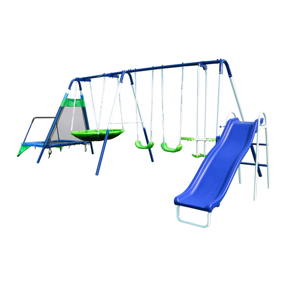
- Page 2 INTRODUCTION Dear Valued Customer, Congratulations on your Sportspower play set purchase! Please read and completely understand the contents of this owner’s manual. This manual contains specific instructions and warnings that must be followed to prevent injuries. This play set is for residential use only. This play set is NOT intended for public or commercial use. The warranty will be voided if the play set is used in a commercial application.
- Page 3 IMPORTANT INSTRUCTIONS AND WARNINGS WARNING READ ALL INSTRUCTIONS BEFORE AS S E MB L ING OR USING THIS EQUIPMENT AGE LIMIT This product is designed to be used by up to eight (8) children between the ages of 3 to 8. Maximum user weight is 100 pounds (45.4kg) each with a combined maximum weight of 800 pounds (363kg).
- Page 4 Some consumers want an anchoring system that allows the product to be moved to different locations. Other consumers want to keep their swing set in a permanent location. There are different types and different methods of anchoring this product. Sportspower does not make a specific anchoring recommendation as each consumer’s need and conditions can vary.
- Page 5 DO NOT allow children to twist the swing chains or ropes, or loop them over the top support bar as this may reduce the strength of the chain or rope. DO NOT swing empty seats as this may cause injuries. ...
- Page 6 - A sagging, broken bed. - Sharp protrusions on the frame or suspension system. - Protrusions of any types (especially sharp typed) on the frame, springs or mat. - Loose stitching or any kind of deterioration of the mat. If any of the above conditions exist, restrict use until proper repairs or replacements are made. ...
- Page 7 INSPECTION PRIOR TO EACH USE OR DAILY INSPECTION DO NOT use the equipment if any bolts or nuts are missing or loose. ALWAYS check to ensure the equipment and all parts are well secured and stable before each use. ...
- Page 8 IMPORTANT CONSUMER INFORMATION SHEET The Consumer Product Safety Commission estimates there are more than 200,000 playground related injuries involving children each year. Injuries involving this hazard pattern tend to be among the most serious of all playground injuries and have the potential to be fatal, particularly when the injury is to the head. The surface under and around playground equipment can be a major factor in determining the injury-causing potential of a fall.
- Page 9 ANCHORING (NOTE:ANCHORS ARE NOT INCLUDED-MUST BE PURCHASED SEPARATELY) There are different ways of anchoring the equipment, depending on the type of ground on which the equipment is to be installed. Make sure that all anchors are below ground level to prevent tripping.
- Page 10 FRAME LEG 12-5/8” CONCRETE 5” 2” BRICK OR GRAVEL BED Note: The maximum fall height for this product is 6 feet. The minimum ground clearance between the bottom of the suspended plays and the playing or ground surface must be 8 inches. 8”...
- Page 11 CARE AND MAINTENANCE CHECKLIST AT THE BEGINNING OF EACH PLAY SEASON: Tighten all hardware. Lubricate all metallic moving parts per manufacturer’s instructions. Check all protective coverings on bolts, pipes, edges, and corners. Replace if they are loose, cracked, or missing.
- Page 13 Parts for swing set frame CORNER TOP BAR MIDDLE TOP BAR TOP BAR TOP BAR LEG WITH FOAM LEG (WITH THREE HOLES) CROSS BAR (WITH TWO HOLES) CROSS BAR (WITH FOUR HOLES) Hardware for swing set frame BOLT 5/16”*2.5” (8MM*63MM) BOLT 5/16”*2.5”...
- Page 14 Parts for flying saucer PVC COVERED CHAIN (PRE-ASSEMBLED) LONG EYE BOLT WITH CHAIN ( PRE-ASSEMBLED) SHORT EYE BOLT WITH CHAIN ( PRE-ASSEMBLED) BRACKET FLYING SAUCER TUBE FLYING SAUCER BRACKET CLAMP Hardware for flying saucer F1-1 BOLT 3/8”*3.3” (9.5MM*85MM) REINFORCING STEEL SPACER NYLON NUT 3/8’’...
- Page 15 Parts for trampoline PROTECTIVE NET JUMP MAT FRAME PAD T4A-N L-SHAPED TUBE (LEFT) T4B-N L-SHAPED TUBE (RIGHT) T5-N STRAIGHT TUBE T6-N HANDLE BAR WITH FOAM T7A-N HANDLE BAR BASE TUBE(LEFT) T7B-N HANDLE BAR BASE TUBE(RIGHT) SUPPORTING TUBE SPRINGS Hardware for trampoline BOLT 5/16”*63MM BOLT 5/16”*40MM ARC WASHER 5/16”...
- Page 16 Bracket for glide ride BRACKET BRACKET CLAMP REINFORCING STEEL SPACER BOLT 5/16”*1” (8MM*25MM) NYLON NUT 5/16’’ Parts for glide ride L1-N TOP SECTION HANGER L2-N GLIDE SEAT SUPPORT TUBE CAP(PRE-ASSEMBLED) SMALL NYLON BEARING (PRE-ASSEMBLED) LARGE NYLON BEARING (PRE-ASSEMBLED) GLIDE SEAT FOOTREST...
- Page 17 Hardware for glide ride BOLT 1/4”*1.5” (6.5MM*37MM) BOLT 1/4’’*1.7” (6.5MM*43MM) SCREW 0.22”*3/4” (5.5MM*19MM) J-BOLT SPRING WASHER (MEDIUM) CAP BOLT 1/4”*5/10” (6.5MM*14MM) CAP NUT 1/4” NUT 1/4” SPRING WASHER (LARGE) SPRING WASHER (MEDIUM) Parts for swing seat PVC COVERED CHAIN (PRE-ASSEMBLED) EYE BOLT WITH ATTACHMENT BOLT (PRE-ASSEMBLED)
- Page 18 Parts for slide RIGHT PLASTIC PANEL LEFT PLASTIC PANEL PLASTIC SHEET H3 CONNECTING PLATE BACK SUPPORT PANEL CONNECTING PLATE UPPER CONNECTING PLATE X1-N METAL LEG X2-N LEFT SUPPORTER BAR X3-N RIGHT SUPPORTER BAR X4-N SUPPORTER BAR METAL BRACKET LADDER STEP Hardware for slide BOLT 1/4”*13MM BOLT 1/4”*16MM...
- Page 19 ASSEMBLY INSTRUCTIONS Place the playground equipment on level ground and not less than 6ft (1.8m) from any structure or obstruction such as a fence, garage, house, overhanging branches, laundry line, or electrical wires. Do not install the playground equipment over concrete, asphalt, packed earth, or any other hard surface;...
- Page 20 REFERENCE FOR AREA OF INSTALLATION STEP 1 – Assemble top bar of swing set frame Connect A1, A3, A2, A4 and A1 and secure with B1, B5, B4 and B3 as shown below. Note: All round holes should be facing up and concave holes facing down. IMPORTANT NOTE: A3 is not symmetrical.
- Page 21 REFERENCE FOR AREA OF INSTALLATION Step 2 – Assemble the side of swing set with trampoline attachment Slide A5 through T1 and connect to A1 using B1, B5, B4 and B3.
- Page 23 REFERENCE FOR AREA OF INSTALLATION STEP 4 – Assemble outer support legs swing set frame Connect A6 to A1 and secure using B1, B5, B4 and B3. Attach A8 to the outward facing side of A6 and secure using B2, B6, B4 and B3. IMPORTANT NOTE: The 2 extra holes on A8 will be used for connecting the slide in later steps.
- Page 24 STEP 5 – Assemble trampoline frame to the swing set Insert the ends of T8 into the sockets of A5. Align the holes and secure using T15, T19, T18 and T13 as shown. Connect T4A-N, T4B-N and T5-N using T16, T19 (2), T18 and T13 and insert T4A-N and T4B-N into the sockets of T8 as shown below.
- Page 25 STEP 6 – Assemble trampoline frame legs Align the holes on the trampoline frame legs (T7A-N and T7B-N) to the welding brackets on the corner of the assembled trampoline frame. Secure the top hole using T10 (which is longer than T11), T12 and T14.
- Page 26 STEP 7 – Attach the jump mat IMPORTANT: MAKE SURE TO WEAR HEAVY DUTY GLOVES AND PROTECTIVE EYE GOGGLES WHEN INSTALLING SPRINGS TO AVOID INJURIES. Lay out the jump mat (T2) in the center of the trampoline frame. Attach spring (T9) with the hook face down to the triangle rings on the four corners of the mat as T4A-N...
- Page 27 Attach all remaining springs as shown in FIGURE 3. T4A-N T4B-N T5-N FIGURE 3...
- Page 28 STEP 8 – Attach the Frame Pad Slide the Frame Pad (T3) through the trampoline legs and fully cover all springs and trampoline frame. IMPORTANT: MAKE SURE ALL METAL PARTS ARE COVERED TO AVOID INJURIES FROM BODY CONTACT. T7A-N T7B-N...
- Page 29 STEP 9 – Attach handle bar to trampoline frame Connect Handle Bar with Foam (T6-N) to T7A-N and T7B-N. Align holes and secure using T17 and T20. T6-N T7A-N T7B-N...
- Page 30 STEP 10 – Secure trampoline to swing set frame Pull the hook with elastic band (stitched onto T1) under T8 and attach the hook to the triangle ring underneath the pad as shown. Tie all straps sewn onto T1 around T8 as shown.
- Page 31 STEP 11 – Secure jump pad to trampoline Loop the straps located beneath the jump pad through the nearest triangle rings and securely tie a bow knot as shown. Make sure all straps are securely fastened and the jump pad is fully covering all metal parts.
- Page 32 STEP 12 – Flying Saucer Assembly Slide the smaller ends of R4 tubes into the pockets of Flying Saucer (R7). Connect the four tubes together. Align the holes with the round holes face down. Connect the chain (R1) to the flying saucer by inserting R2B (shorter screw) and securing with F3 and F4 as shown below.
- Page 33 STEP 13 – Attach Flying Saucer to Swing Set Frame Attach R8 and R3 to the top bar using F1-1, F2 and F3 as shown in Diagram A. Insert R2A (pre-assembled with R1) into R3 and secure with F2 and F3 as shown in Diagram F1-1 F1-1 DIAGRAM A...
- Page 34 Swing Seat Assembly STEP 14 - Connect swing set chains to the top bar by inserting J3 through A4 and securing with J8 and J6 as shown in Diagram A. Connect swing seat to the chains by inserting J3 through K1 and secure with J7, J9 and J6 as shown in Diagram B.
- Page 35 - Glide Ride Assembly STEP 15 Attach L4 and L3 to A4 using N3R, L5 and N7 as shown. Use special socket wrench and screwdriver to tighten N3R and N7. USE SPECIAL SOCKET WRENCH AND SCREW DRIVER TO TIGHTEN...
- Page 36 STEP 16 – Glide Ride Assembly (continued) Insert L1-N (straight end) into M5 and secure with N4 and N12 on both sides. Attach M1 to the top of L1-N (curved end). Align holes and insert M2. L1-N...
- Page 37 STEP 17 – Glide Ride Assembly (continued) Attach L1-N to L3 on both sides and secure with N2R and N10. L1-N L1-N...
- Page 38 STEP 18 – Glide Ride Assembly (continued) Attach L2-N to L1-N on both sides and secure with N5, M3 (2), N11 and N8. Concave holes face up Round holes face down L1-N L2-N L2-N...
- Page 39 STEP 19 – Glide Ride Assembly (continued) Attach M4 to L2-N and secure with N1, N6 and N9. L2-N L2-N...
- Page 40 Slide assembly STEP 20 - Slide the end of H3 into the slot of H4. Align the holes on H3 to H1 and H2, and then slide H4 into the slots of H1 and H2. Secure H3 to H1 and H2 using H10 and H15 in all places shown below. IMPORTANT NOTE: do not tighten H10 until all screws have been properly attached to H1 and H2.
- Page 41 Slide Assembly (continued) STEP 21 - Turn the slide over and attach H7 to the top end of H3. Align the holes and secure with H12 and H15. Place H5 onto H1 and H2. Place H6 into the slots on H5 as shown below. Align holes and secure using H11 and H15.
- Page 42 STEP 22 – Slide Assembly (continued) Insert X2-N into H2 and X3-N into H1. Insert the small ends of X1-N into X2-N and X3-N as shown below (align the holes). Place X4-N in between X1-N as shown below (align the holes) and secure with H18 and H16. X2-N X3-N X4-N...
- Page 43 STEP 23 – Slide Assembly (continued) Attach X5 to H1. Secure together with handle bar (X3-N) using H13, H16 and H15. Secure X2-N to H2 with H13 and H15. X2-N X3-N...
- Page 44 STEP 24 – Assemble Step Ladder Attach X6 between X1-N and secure with H14, H16 (2) and H17 as shown below. X1-N X1-N...
- Page 45 STEP 25 – Connect Slide to Swing set Attach the assembled slide unit. Secure X5 to A8 using H14, H16 (2), and H17 on both brackets as shown below.
- Page 46 Congratulations! You have now completed the swing set assembly. Please make sure to thoroughly check all parts and hardware to make sure all bolts and nuts are well secured before using the playground equipment. WARNING - Do not let children use the playground equipment until it is properly assembled and anchored.
Need help?
Do you have a question about the MSC-3878 and is the answer not in the manual?
Questions and answers
Trampoline springs don’t reach the mat
The trampoline springs for SPORTSPOWER MSC-3878 may not reach the mat if the trampoline is not properly assembled. Possible reasons include:
- Incorrect alignment of the trampoline frame or legs.
- Springs not attached with the hook facing down as required.
- The jump mat not centered correctly within the frame.
- Missing or damaged springs.
Ensure all parts are correctly assembled and follow the instructions, including wearing gloves and eye protection when installing springs.
This answer is automatically generated