Table of Contents
Advertisement
Quick Links
Advertisement
Table of Contents

Related Manuals for Kanomax ANEMOMASTER A031


Summary of Contents for Kanomax ANEMOMASTER A031
- Page 1 CLIMOMASTER ANEMOMASTER MODEL A031/A041/A034/A044 Operation Manual Read this manual carefully and understand the warnings described in this manual before operating the product. Keep this manual handy for future reference. 02001 06.07 No. 603101...
- Page 2 Thank you for purchasing a product of Kanomax, Inc. Please read this operation manual carefully and operate the instrument appropriately by following the instructions given in this manual.
- Page 3 List of Components ■ Standard Item Model Qty. Feature and Functions Straight probe. A031 Measures air velocity, air temperature and volumetric flow rate. Articulating probe. A034 Measures air velocity, air temperature and volumetric flow Main Body rate. & Straight probe. Probe A041 Measures air velocity, air temperature, volumetric flow...
- Page 4 Important Safety Information [Classifications] Danger: To Prevent Serious Injury or Death Warnings in this classification indicate danger that may result in serious injury or death if not observed. Caution: To Prevent Damage to the Product Warnings in this classification indicate risks of damage to the product that may void the product warranty if not observed.
- Page 5 Danger Never bring the probe close to a flammable gas atmosphere. --- The heated sensor may cause fire or explosion. Do not use near CLEAR MODE SHAPE ENTER CALC HOLD STORE TIM ECONS. flammable gas ZERO UNIT PRINT Never disassemble, modify or repair the product. --- Failure to observe the above may cause short circuit and/or other failure that will affect the Do not modify / performance.
- Page 6 Caution Always unplug the instrument from the electrical outlet when the instrument is not in use. --- Failure to do so may cause electrical shock, fire or circuit damage. Remove the batteries from the battery compartment when storing the instrument. Do not leave exhausted batteries in the battery compartment.
-
Page 7: Table Of Contents
Table of Contents 1. Part Names and Functions ..................1 1.1 Overview ..........................1 1.2 Main Body........................... 2 1.3 Touch Panel ......................... 3 1.4 Probe ........................... 4 2. Getting Started ......................5 2.1 Installing Batteries ......................5 2.2 Turning ON/OFF the Power....................6 2.3 Precautions for Measurements .................... - Page 8 13. Troubleshooting....................... 30 14. Warranty and After Service................... 32 15. Contact Information....................34...
-
Page 9: Part Names And Functions
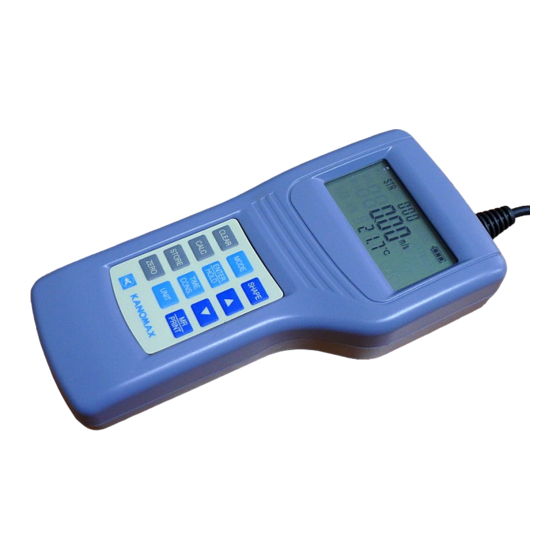
1. Part Names and Functions 1.1 Overview Probe Approx. φ6mm Main Body Probe Cable (Approx. 2m) MODE SHAPE CLEAR HOLD CALC ENTER TIME STORE CONS. Approx.φ13mm ZERO UNIT PRINT... -
Page 10: Main Body
1.2 Main Body Approx. 88mm Probe Socket Pressure Port (Optional) LCD Display Analog Output Terminal (Optional) RS232C Terminal DC Input Terminal Power Switch I : ON O: OFF CLEAR MODE SHAPE ENTER CALC HOLD TIME STORE CONS. Touch Panel ZERO UNIT PRINT Battery... -
Page 11: Touch Panel
1.3 Touch Panel Flow Volume Air Temp. MODE Key: To change Air Velocity Differential Pressure measurement mode. Air Temp CLEAR Key: (A041/A044) To clear stored data. CALC Key: SHAPE Key: To obtain average, To select duct type max and min. and size for measuring CLEAR MODE... -
Page 12: Probe
1.4 Probe Straight Probe (ModelA031/A041) Air Velocity Sensor Direction Mark Temp. Sensor and Temp. Compensation Sensor Approx. φ6mm Articulating Probe (ModelA034/A044) How to extend the Articulating Probe: 1. Hold the upper part ① of the probe, and unscrew ②. 2. Pull out the flex-neck ③. Fix the probe in its extended position by holding ①... -
Page 13: Getting Started
2. Getting Started 2.1 Installing Batteries Backside of the body 1. Press down the battery cover with your finger as shown left. 2. Slide the cover toward the bottom of the instrument until it stops. 3. Lift the cover away from the body. Types of Batteries that can be Used Manganese (R6), AA batteries Alkaline (LR6), AA batteries... -
Page 14: Turning On/Off The Power
2.2 Turning ON/OFF the Power The power switch for turning ON/OFF the instrument is located at the side of the instrument. When powered up, the LCD test screen will be displayed, which will switch to the Air Velocity / Air Temperature measurement screen in approx. - Page 15 ■ Battery Level Indicator Check the “battery level indicator” to confirm the remaining battery level. The battery consumption rate largely depends on the measured air velocity. When the battery drops to a level requiring replacement, the indicator will start blinking. The screen may freeze if high velocity is measured after the battery level indicator starts blinking.
-
Page 16: Precautions For Measurements
2.3 Precautions for Measurements Direction Mark 2.3.1 Air Velocity Measurement Precautions Probe has its own directivity characteristics. Make sure that the direction mark is facing against the airflow (for details of the directivity characteristics, refer to Section 12 “Probe Directivity”). If you are not sure of the airflow Airflow direction, slowly rotate the probe and select the point where you get the maximum velocity reading,... - Page 17 <Zero Adjustment Procedure> Display Description Press key to enter the pressure measurement screen. Press and hold the key for more than 2 seconds. The pressure value will be 0.00 kpa. <Connecting the Pressure Tube> Connect the pressure tube to the (+) or (-) pressure port as shown right.
-
Page 18: Duct Shape And Size
3. Duct Shape and Size Before measuring the volumetric flow rate, duct shape and size setting must be made. Duct Shape: There are two duct shapes - Rectangular and Circular, which are indicated as at the lower right corner of the LCD screen. Size of duct: For a rectangular duct, set the width (W) and height (H). -
Page 19: Measurement
4. Measurement When the instrument is turned on, the LCD test screen will be displayed for approx. 2 seconds. The test screen will then switch to the Air Velocity / Air Temperature measurement screen. The reading will be updated each second. 4.1 Changing the Measurement Mode To change the measurement mode, press the key while each measurement screen is displayed. -
Page 20: Hold The Reading
4.2 Hold the Reading Display Description While measuring, press the key to hold the current reading. HOLD mark will be displayed at the upper right of the reading while the reading is held. To recover from the hold mode, press the key again. -
Page 21: Setting The Time Constant
4.3 Setting the Time Constant When there is rapid change in the measurement data, the readings may become difficult to read. In such case, the speed of updating the readings can be reduced by changing the time constant setting. Time constant determines the time span of the moving average. When a larger (longer) time constant is selected, the readings will be rather stable, and when a smaller (shorter) time constant is selected, the readings will be more responsive and sensitive to the change. -
Page 22: Data Storage And Statistical Calculation
5. Data Storage and Statistical Calculation 5.1 Storing Measurement Data Measurement data can be stored in the built-in memory of the instrument. The instrument can hold up to 800 data records. When storing the measurement data, average, maximum and minimum values will be calculated for the data group to be stored. -
Page 23: Data Storage And Statistical Calculation Procedure
5.2 Data Storage and Statistical Calculation Procedure Data storage procedure will be described below by taking an example of an operation in the “Air Velocity / Air Temperature Measurement Mode”. Data storage procedure is same in other modes as well. Display Description <... - Page 24 Display Description < Storing the Calculation Result > ⑤ To store the calculation result, press the key while either average, maximum or minimum value is displayed. The calculation data will be stored as a data group. The display will return to the original measurement mode and the temporary memory will be cleared.
-
Page 25: Viewing And Deleting Stored Data
5.3 Viewing and Deleting Stored Data The average, maximum and minimum value of the stored data can be viewed on the display and deleted. Only the calculation result can be viewed from the instrument. To view each data of the data group, the data must be printed out from an optional printer (please refer to section 7 “Data Output”... -
Page 26: Setting The Measurement Unit And Baud Rate
6. Setting the Measurement Unit and Baud Rate List of Measurement Units: < Unit Conversion Table > Air velocity: m/s, FPM Air temperature: Air Velocity: 1m/s=196 FPM Volumetric flow rate: m /h, m /min, ft /min Air Temperature: T( F)=1.8×T( C)+32 Length: mm, inch Volumetric Flow: 1m... -
Page 27: Data Output
7. Data Output 7.1 Printing Out the Measurement Data RS232C To print out the stored measurement data, an optional printer and printer cable Terminal are required. The printer cable must be connected to the RS232C terminal located at the side of the instrument. 7.1.1 Preparation for Print Out Equipment (Optional ) - Printer... -
Page 28: Printing Directly From The Measurement Mode
7.1.2 Printing Directly from the Measurement Mode Procedure for printing directly from the measurement mode will be described below taking an example of an operation in the “Air Velocity / Air Temperature Measurement Mode”. Display Description ① Hold the reading by pressing the key. -
Page 29: Printing Out Stored Data
7.1.4 Printing Out Stored Data Procedure of printing the stored data will be described below by taking an example of printing the sixth data group stored in the “Air Velocity / Air Temperature Measurement Mode”. Display Description ① Press the key in the measurement mode. -
Page 30: Printout Examples (Stored Data)
7.1.5 Printout Examples (Stored Data) Measurement Modes Air Velocity / Volumetric Flow / Pressure / Air Temperature Air Temperature Air Temperature EXAMPLE for group DNo006 EXAMPLE for group DNo006 EXAMPLE for group DNo006 (When duct shape is Rectanglular.) DNo.006 DNo.006 DNo.006 Duct Shape R Size 2550*2550mm 001 Vel 0.15m/s Temp 21.8... -
Page 31: S232C Serial Communication
7.3 S232C Serial Communication For serial communication, the RS232C cable must be connected RS232C terminal to the RS232C terminal located at the side of the instrument. <Equipment > - Computer - RS232C Communication Cable - Communication Software (PC-LINK Software: For transferring stored data to the PC. Data Acquisition Software: For transferring real time data to the PC.)... -
Page 32: Cleaning The Probe
8. Cleaning the Probe When the sensor is contaminated with impurities such as dust, particles, soot or machine oil, the heat dissipation rate will change. In most cases, heat dissipation will decrease, resulting in lower air velocity readings. This is same for the probes which are equipped with a mesh cover. The same problem will occur if the mesh is deformed, or clogged with impurities. -
Page 33: Specifications
9. Specifications Product Anemomaster Model A031, A041, A034, A044 Measuring Object Clean Air Flow Measuring Air Velocity 0.10 to 30.0 m/s (0.00 to 9.99m/s: 0.01m/s, 10.0 to 30.0m/s: 0.1m/s) Range Air Temperature -20.0 to 60.0 °C (0.1°C) (Resolution) Pressure* -5.00 to +5.00 kPa (0.01kPa) Duct Size Range 0 to 2550mm (0 to 255inch) Air Velocity... -
Page 34: Measurement Principles
10. Measurement Principles Hot-wire Anemometer Principle When the heated air velocity sensor is exposed to airflow, the Current sensor temperature will change by the heat drawn by the airflow. Accordingly, the sensor resistance value will change. This change in the resistance value will vary largely as the air velocity Airflow increases. - Page 35 Air Temperature Measurement An air temperature element (platinum thin film element) which its resistance value changes by the air temperature is incorporated in one side of the bridge. The air temperature can be obtained by measuring the variance in the resistance value.
-
Page 36: Air Velocity Compensation
11. Air Velocity Compensation When the heated air velocity sensor of the instrument is exposed to airflow, the heat is drawn from the sensor. The instrument obtains air velocity readings by using this relationship between the amount of heat removed (heat dissipation) and air velocity. -
Page 37: Probe Directivity (Air Velocity)
12. Probe Directivity (Air Velocity) 12.1 Horizontal Directivity 0° 120% 110% 100% Direction Mark -180° 90° -90° +90° 0° -90° 180° When Air Velocity is 5m/s 12.2 Vertical Directivity 0° 120% 110% 100% 0° Direction Mark -90° +90° 90° -90° -180°... - Page 38 13. Troubleshooting 13.1 Troubleshooting Refer To Symptom Possible Cause / Solution (Page No.) Battery is inserted in wrong polarity. Display does not appear when power → Turn off the power and insert the battery correctly. is turned ON. Battery is drained. 5, 6 →...
- Page 39 13.2 Various Status Displays Description Display The number of stored data records has exceeded the maximum limit of 800 data records. Stored data must be deleted to enable further data storage. Printing failure. Confirm the communication setting and cable connection. Also confirm that the printer is in normal operating condition.
- Page 40 14. Warranty and After Service 14.1 Kanomax Limited Warranty The limited warranty set forth below is given by KANOMAX JAPAN, Inc. (hereafter referred to as “KJI”) with respect to the KANOMAX brand anemometer, and its attachment parts including probe and other accessories (hereafter referred to as “PRODUCT”) purchased directly from KJI or from an authorized distributor.
- Page 41 During the warranty period, we will repair at no charge a product that proves to be defective due to material or workmanship under normal use. (See Section 14.1 Kanomax Limited Warranty) All return shipping charges are the responsibility of the customer.
- Page 42 15. Contact Information U.S.A. KANOMAX USA, INC. PO Box 372, 219 Route 206, Andover, NJ 07821 U.S.A. Tel: (800)-247-8887 / (973)-786-6386 FAX: (973)-786-7586 URL: http://www.kanomax-usa.com/ E-Mail: info@kanomax-usa.com JAPAN KANOMAX JAPAN, INC. 2-1 Shimizu Suita City, Osaka 565-0805, Japan TEL: 81-6-6877-0183 FAX: 81-6-6879-2080 URL: http://www.kanomax.co.jp/...
Need help?
Do you have a question about the ANEMOMASTER A031 and is the answer not in the manual?
Questions and answers