Table of Contents
Advertisement
Available languages
Available languages
Quick Links
VAIE 7M04
VAIE 7M06
FBT ELETTRONICA S.p.A. - Via Paolo Soprani, 1 - ZONA IND. SQUARTABUE - 62019 RECANATI (MC) - ITALY
TEL. 071750591 r.a. - FAX 0717505920 - P.O. BOX 104 - E-mail: info@fbt.it - www.fbt.it
Sistemi d'evacuazione compatti
1000W / 4 ZONE
1000W / 6 ZONE
ISTRUZIONI PER L'USO
VAIE 7M00
Montaggio a parete
0068/CPR/069-2019
Advertisement
Chapters
Table of Contents

Related Manuals for Fbt VAIE 7M00 Series


Summary of Contents for Fbt VAIE 7M00 Series
- Page 1 1000W / 6 ZONE ISTRUZIONI PER L’USO FBT ELETTRONICA S.p.A. - Via Paolo Soprani, 1 - ZONA IND. SQUARTABUE - 62019 RECANATI (MC) - ITALY TEL. 071750591 r.a. - FAX 0717505920 - P.O. BOX 104 - E-mail: info@fbt.it - www.fbt.it...
-
Page 3: Table Of Contents
VAIE 7M00 SOMMARIO 1. AVVERTENZE 1.1 Alimentazione e messa a terra 1.2 Note di sicurezza 2. INTRODUZIONE 2.1 Panoramica del sistema 2.2 Caratteristiche funzionali 2.3 Confi gurazione tipo 3. DESCRIZIONE GENERALE 3.1 Pannello frontale 3.2 Vista interna 4. INSTALLAZIONE E CONNESSIONI 4.1 Installazione a parete 4.2 Collegamenti 4.2.1... -
Page 4: Avvertenze
1.2 NOTE DI SICUREZZA Tutti gli apparecchi FBT sono costruiti nel rispetto delle più severe normative internazionali di sicurezza ed in ottemperanza ai requisiti della Comunità Europea. Per un corretto ed effi cace uso dell’apparecchio è importante prendere conoscenza di tutte le caratteristiche leggendo attentamente le presenti istruzioni ed avvertenze. -
Page 5: Introduzione
VAIE 7M00 2. INTRODUZIONE 2.1 PANORAMICA DEL SISTEMA La nuova gamma VAIE 7M00 comprende due sistemi di evacuazione vocale integrati per impianti d’emergenza, appositamente studiati per il montaggio a parete e dotati di un’unità di controllo certifi cato conforme a norme EN 54-16:2008 e EN 54-4. Questi sistemi sono in grado di gestire, a seconda del modello, da 4 a 6 zone d’allarme –... -
Page 6: Configurazione Tipo
VAIE 7M00 2.3 CONFIGURAZIONE TIPO... -
Page 7: Descrizione Generale
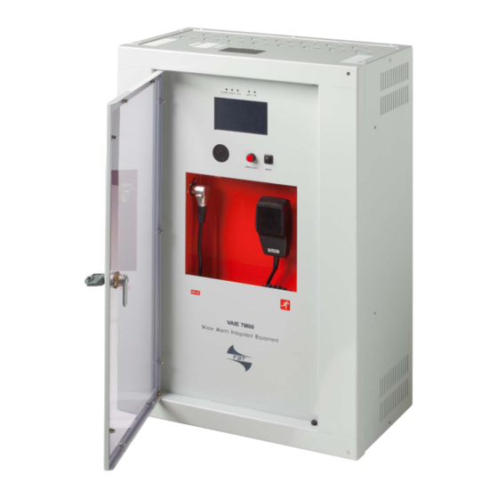
VAIE 7M00 3. DESCRIZIONE GENERALE 3.1 PANNELLO FRONTALE Display 4.3” retroilluminato con touchscreen per la selezione delle zone di Allerta/Evacuazione e navigazione per regolazione livelli, confi gurazione dell’apparecchio, visualizzazione guasti. Altoparlante integrato per il riascolto dei segnali in uscita dalle zone oppure dei segnali delle sorgenti in ingresso e per la riproduzione della segnalazione acustica di guasto rilevato (beep). -
Page 8: Vista Interna
VAIE 7M00 3.2 VISTA INTERNA n°7 contatti d’ingresso controllati. n°3 contatti d’uscita a relè. Ingresso RJ45 per postazioni microfoniche d’emergenza (max 4) Ingresso RJ45 per postazioni microfoniche broadcast (max 16). Ingressi/uscite REMOTE LINK A/B RJ45 per collegamento ad altri sistemi VAIE 7M00 e/o VAIE 7500 (max 6 totali). Morsettiera ingresso per sorgenti ausiliarie con contatto di precedenza. -
Page 9: Installazione E Connessioni
VAIE 7M00 4. INSTALLAZIONE E CONNESSIONI IMPORTANTE Si ricorda che le operazioni riportate in questa sezione del manuale devono essere eseguite ESCLUSIVAMENTE da personale specializzato, addestrato e qualifi cato all’installazione ed alla manutenzione dell’apparecchio: l’apertura del VAIE rende accessibili parti ad alto rischio di scosse elettriche. È... -
Page 10: Collegamenti
VAIE 7M00 4.2 COLLEGAMENTI IMPORTANTE Verifi care che l’interruttore magnetotermico a monte sia SPENTO. Se così non fosse, provvedere a portarlo in posizione OFF prima di eseguire qualsiasi altra operazione all’interno dell’armadio: pericolo di scossa elettrica. Procedere al collegamento dei vari dispositivi, facendo riferimento ai relativi paragrafi : Circuito CPU A) Par. - Page 11 VAIE 7M00 4.2.1 COLLEGAMENTO POSTAZIONI D’EMERGENZA CIRCUITO CPU Utilizzare un cavo CAT.5e SF/UTP per collegare la presa EMERG. (11) alle prese ‘IN/OUT’ delle postazioni remote d’emergenza Serie FMD (max 4) o in alternativa TSC6000-EN (max 2). La massima distanza di collegamento tra il cestello e l’ultima postazione non deve superare i 1000 metri.
-
Page 12: Collegamento Verso Altri Vaie 7M00 / Vaie 7500
Audio + Audio – – Precedenza OUT PREC Non collegato +Vcc Seriale + Fig. 1 Fig. 2 Seriale – Schermo Per dettagli di collegamento e colore dei fi li, fare riferimento al manuale delle basi MBT 1101 (cod. FBT 37781). -
Page 13: Collegamento Ingresso Musica
VAIE 7M00 4.2.5 COLLEGAMENTO INGRESSO MUSICA CIRCUITO CPU I morsetti MUSIC (15) sono disponibili per la connessione di sorgenti musicali esterne (lettore CD, tuner etc.). 4.2.6 COLLEGAMENTO CONTATTI D’INGRESSO CIRCUITO CPU Alla morsettiera CONTACT (9) sono disponibili 7 contatti d’ingresso: in fi gura un esempio di collegamento dove i contatti 1, 2, 3, 5 e 6 sono di tipo sorvegliato mentre i contatti 4 e 7 non lo sono. -
Page 14: Collegamento Uscite Relè
VAIE 7M00 4.2.7 COLLEGAMENTO USCITE RELÈ CIRCUITO CPU Ai morsetti R1, R2 e R3 (10) sono disponibili 3 uscite a relè per segnalazione verso periferiche esterne. 4.2.8 COLLEGAMENTO 21÷29 V CIRCUITO CPU Ai morsetti 24V (20), a seconda delle modalità di funzionamento del VAIE, è possibile prelevare un’alimentazione compresa tra i 21 e i 29 V, con un assorbimento massimo di 50 mA. - Page 15 VAIE 7M00 4.2.10 COLLEGAMENTO AMPLIFICATORE DI RISERVA CIRCUITO AMPLIFICATORI Utilizzando i morsetti R (18) in combinazione con i morsetti A/B (19) è possibile impostare uno degli amplifi catori come riserva. La fi gura illustra il collegamento di un modello VAIE 7M04 (3 zone + riserva) e di un VAIE 7M06 (5 zone + riserva). SISTEMA 3 ZONE + RISERVA SISTEMA 5 ZONE + RISERVA VAIE 7M04...
-
Page 16: Collegamento Alimentazioni
VAIE 7M00 4.2.11 COLLEGAMENTO ALIMENTAZIONI CIRCUITO CHARGER E MORSETTIERA IMPORTANTE Verifi care che l’interruttore magneto-termico a monte sia SPENTO. Se così non fosse, provvedere a portarlo in posizione OFF prima di eseguire qualsiasi altra operazione all’interno dell’armadio: pericolo di scossa elettrica. IMPORTANTE Questi apparecchi sono stati progettati per essere connessi ad una rete d’alimentazione compresa di... -
Page 17: Operatività E Nomenclatura
VAIE 7M00 5. OPERATIVITÀ E NOMENCLATURA Di seguito un elenco delle modalità di segnalazione delle condizioni operative del sistema e di defi nizioni utilizzate nei successivi paragrafi del manuale, completate da indicazioni di carattere generale. 5.1 SEGNALAZIONE DELLE CONDIZIONI OPERATIVE Il VAIE è... -
Page 18: Struttura Dei Menu
VAIE 7M00 7. STRUTTURA DEI MENU Il VAIE permette l’accesso alle funzioni del sistema tramite una serie di Pannelli di Gestione raggruppati, secondo tipologia operativa e destinazione d’uso, in Menu Opzioni accessibili dalla fi nestra MAIN MENU; inoltre, ai seguenti Menu Opzioni sono stati assegnati diff... -
Page 19: Uso Del Sistema
VAIE 7M00 MENU <CONFIGURATION> | 3° LIVELLO DI SISTEMA Terzo livello d’accesso, per il personale istruito ed autorizzato ad operare sulle funzioni avanzate del sistema e modifi care i parametri di confi gurazione, per avviamento e modifi ca impianto. Per accedere a questo menu è necessario inserire la password d’accesso relativa. -
Page 20: Configurazione Dell'impianto
VAIE 7M00 8.1 CONFIGURAZIONE DELL’IMPIANTO Le operazioni di confi gurazione devono essere eff ettuate da personale qualifi cato ed adeguatamente addestrato a tale scopo. Password Dal MUSIC MENU passare al MAIN MENU e selezionare la voce < CONFIGURATION >: se la restrizione d’accesso con password è... - Page 21 VAIE 7M00 Confi gurazione rack Nel menu CONFIGURATION, scorrere le voci e selezionare ‘set>RACK CONFIG’. Da questa schermata è possibile confi gurare tutte le impostazioni di base dell’impianto. D1) >> System Nella schermata ‘System confi guration’ impostare tramite i tasti [ + ] e [ – ]: Rack address: indirizzo ID del VAIE (da 0 a 5).
- Page 22 VAIE 7M00 D3) >> Local emergency Schermata per l’impostazione di default delle zone di diff usione per i messaggi d’emergenza. Il pannello riporta la situazione di tutti i VAIE presenti nell’impianto. Spostarsi sulla tabella utilizzando le frecce e i tasti Up/Dn. Le zone selezionate in questa fi...
- Page 23 è collegata (ad es., se la base locale è collegata al cestello n°2, il tasto 1 corrisponde alla zona 13, il 2 alla zona 14 e così via). Come postazione locale si consiglia di utilizzare il modello FBT MBT 1106. - selezione di una eventuale card opzionale presente nell’apparecchio (ACVAIE-2IN o ACVAIE-6IN).
-
Page 24: Menu Music
VAIE 7M00 8.2 MENU MUSIC IMPOSTAZIONE DEI PARAMETRI AUDIO DELLE SORGENTI BGM Schermata Descrizione pannello principale Descrizione opzioni I nuovi sistemi serie VAIE 7M00 Pannello di controllo delle sorgenti musica, consentono, attraverso i singoli pannelli, visualizzato dal VAIE in condizioni di la selezione indipendente su ogni zona normale operatività... -
Page 25: Menu
VAIE 7M00 8.3 MENU <AUDIO SETTING> IMPOSTAZIONE DEI PARAMETRI AUDIO DELLE SORGENTI PA Schermata Descrizione pannello principale Descrizione opzioni Pannello di controllo delle sorgenti Le opzioni del menu AUDIO musicali e broadcast, visualizzato dal SETTING permettono l’accesso ai VAIE in condizioni di normale operatività seguenti pannelli: dello “Stato di Quiete”. - Page 26 VAIE 7M00 set> MONITOR SPEAKER Gestione altoparlante monitor In questo pannello, oltre alla regolazione Sorgenti selezionabili del volume dell’altoparlante monitor Local mic / MP3 presente sul VAIE, è possibile il riascolto Emergency units locale dei segnali d’ingresso e Link A input d’uscita dell’apparecchio.
- Page 27 VAIE 7M00 set> CLOCK Visualizzazione data e ora correnti In questa schermata è possibile visualizzare l’ora di sistema (non è possibile eff ettuare modifi che, consentite nei livelli di accesso superiori). Premere ‘Escape’ per tornare alla schermata < AUDIO SETTING >. set>...
-
Page 28: Menu
VAIE 7M00 8.4 MENU <INSPECTION> ISPEZIONE DELLO STATO DEL SISTEMA Menu di selezione opzioni, per ispezione dello stato del sistema. Dedicato al personale responsabile alla verifi ca iniziale delle cause che hanno provocato lo stato di guasto o d’emergenza. Scorrendo il menu è possibile selezionare: Premere Main menu per tornare alla schermata principale. - Page 29 VAIE 7M00 Etichetta Categoria di diagnosi Vedi pannello Note Per ogni elemento Alimentazione primaria e Power supplies sorvegliato viene segnalato secondaria lo stato di diagnosi. Per ogni elemento Control input Contatti d’ingresso locali sorvegliato viene segnalato lo stato di diagnosi. Per ogni elemento Comunicazioni Communication...
- Page 30 VAIE 7M00 report> EVENT LOG Storico eventi Pannello di resoconto, dove vengono riportati il numero totale degli eventi di guasto ed allarme registrati durante il funzionamento del sistema. Premere Fault log view per aprire la visualizzazione dettagliata dei guasti. Premere Alarm log view per aprire la visualizzazione dettagliata degli allarmi. Premere Escape per tornare al menu INSPECTION.
-
Page 31: Menu
VAIE 7M00 8.5 MENU <OPERATOR> GESTIONE DELLE CONDIZIONI D’EMERGENZA, GUASTO E DISABILITAZIONE Menu di selezione opzioni, riservato al personale responsabile alla gestione del sistema in stato d’emergenza e/o guasto. Se in fase di confi gurazione è stata abilitata la password d’accesso, verrà visualizzato il pannello relativo: immettere la password numerica a 4 cifre (per default è... - Page 32 VAIE 7M00 Etichetta Applicazione Vedi pannello Note Pannello dedicato al test sulle linee altoparlanti. Loudspeaker lines Linee diff usori On = test abilitato Off = test disabilitato Pannello dedicato al test sugli amplifi catori locali. Amplifi ers Amplifi catori On = test abilitato Off...
- Page 33 VAIE 7M00 set> CLOCK Impostazione data e ora del sistema Pannello per l’impostazione della data e dell’ora di sistema. Premere sui pulsanti: - Set date (data) - Set time (ora) e - Set cal. (calibrazione) per impostare il parametro relativo. Premere ‘Escape’...
-
Page 34: Menu
VAIE 7M00 8.6 MENU <CONFIGURATION> GESTIONE DELLE FUNZIONI AVANZATE DEL SISTEMA E MODIFICA CONFIGURAZIONE Menu di selezione opzioni di esclusiva pertinenza del personale espressamente istruito ed autorizzato ad operare sulle funzioni avanzate del sistema e modifi care i parametri di confi gurazione, ai fi ni di avviamento e manutenzione impianto. - Page 35 VAIE 7M00 set> IMP. REFERENCE Acquisizione impedenza ed impostazione tolleranza Pannello di acquisizione dei valori di impedenza delle linee ed impostazione della soglia di tolleranza per i test diagnostici. Premere sui pulsanti relativi per accedere ai sub-pannelli. Si ricorda che i nuovi valori di impedenza e di tolleranza , se accettati, dovranno essere memorizzati premendo il tasto ‘Save’.
- Page 36 VAIE 7M00 set> ALARM LEVELS Impostazione di livello delle sorgenti d’allarme Pannello per la regolazione del volume d’uscita delle sorgenti d’allarme collegate al VAIE 7M00. - Postazioni d’emergenza. - Microfono palmare VVF. - Ingresso LINK (connessione con altri VAIE). Premere Escape per tornare al menu CONFIGURATION. set>...
- Page 37 VAIE 7M00 Etichetta Applicazione Vedi pannello Note In questo pannello si impostano: - Indirizzo ID del VAIE (0÷5). - Numero di VAIE presenti nell’impianto. Composizione impianto - Attribuzione amplifi catore di System Amplifi catore di riserva riserva. Vengono inoltre visualizzati in automatico il numero totale di amplifi...
- Page 38 VAIE 7M00 Etichetta Applicazione Vedi pannello Note Pannello per la confi gurazione degli ingressi controllati. Per passare da un ingresso all’altro (da 1 a 7) premere Next e Prev. Premere Mode per selezionare una modalità tra: - Message input > Edit zone - Broadcast >...
- Page 39 1 corrisponde alla zona 13, il 2 alla zona 14 e così via). Come postazione locale si consiglia di utilizzare il modello FBT MBT 1106. Pannello di confi gurazione relativa alle batterie. Premendo su ‘Change’ è possibile impostare: - Capacità...
- Page 40 VAIE 7M00 set> MESSAGE CONFIG. Impostazione messaggi d’emergenza I messaggi di default (allerta, evacuazione e segnale di preavviso di chiamata) sono memorizzati nella memoria fl ash interna del VAIE 7M00. Al fi ne di personalizzare ulteriormente l’impianto, è inoltre possibile caricare fi le .wav personalizzati da dispositivo esterno (SD card o chiavetta USB).
- Page 41 VAIE 7M00 Password Impostazione del codice password Pannello di abilitazione, disabilitazione e personalizzazione della password d’accesso ai livelli di servizio di sistema. Per default, le password impostate sono quelle visualizzate nella fi gura a lato. Per cambiare queste impostazioni ed inserire un nuovo codice, premere sul tasto relativo al menu su cui si vuole operare la modifi...
-
Page 42: Criteri Di Gestione Delle Priorità In Condizioni Di Emergenza
VAIE 7M00 8.7 CRITERI DI GESTIONE DELLE PRIORITÀ IN CONDIZIONI DI EMERGENZA IL SISTEMA GESTISCE LE CONDIZIONI DI EMERGENZA SECONDO DUE CRITERI: 8.7.1 GESTIONE DELLE PRIORITÀ SULLA BASE DELLE RICHIESTE DI EMERGENZA Le richieste di emergenza possono essere di due tipi: EMERGENZA MANUALE: stato di emergenza attivato da operatore tramite il pulsante con led sui comandi locali del cestello o sulle postazioni microfoniche di emergenza. - Page 43 VAIE 7M00 8.8 EMERGENZA MANUALE DI SEGUITO VERRÀ DESCRITTA LA PROCEDURA PER LA GESTIONE DELLE EMERGENZE CON INTERVENTO MANUALE DA PARTE DI UN OPERATORE AUTORIZZATO. 8.8.1 INFORMAZIONI GENERALI L’emergenza manuale è accessibile in qualunque momento e ha priorità sia su messaggi pre-registrati even- tualmente in corso –...
-
Page 44: Emergenza Automatica Stato Di Allarme Attivato Da Periferica Esterna
VAIE 7M00 8.8.4 INVIO EMERGENZA A VIVA VOCE DA POSTAZIONI REMOTE Sollevare il coperchietto di sicurezza sulla postazione e premere 1 volta il tasto EMERGENCY, che si accende in modo fi sso. L’avvenuta messa in stato d’emergenza da parte della postazione viene visualizzata anche su eventuali altre postazioni e sui VAIE collegati (con tasto lampeggiante). -
Page 45: Stato Di Guasto
VAIE 7M00 9. STATO DI GUASTO IL VAIE 7M00 DISPONE DI ROUTINE DIAGNOSTICHE CHE MONITORANO CONTINUAMENTE LA DISPONIBILITÀ DELLE SORGENTI D’EMERGENZA E L’INTEGRITÀ DEL PERCORSO CRITICO DEI SEGNALI ADIBITI ALLA FUNZIONALITÀ DELL’IMPIANTO IN CONDIZIONI D’EMERGENZA. 9.1 OPERATIVITÀ E SEGNALAZIONI DEL SISTEMA IN CONDIZIONE DI GUASTO GENERICO •... -
Page 46: Caratteristiche Tecniche
VAIE 7M00 10. CARATTERISTICHE TECNICHE MODELLO VAIE 7M04 VAIE 7M06 Potenza nominale audio @230Vca 1000 W / D=2,5%* distorsione tipica a 25 W 0,025% Potenza nominale audio @24Vcc 800 W / D=10%* distorsione tipica a 25 W 0,025% Display 4.3” retroilluminato con touch screen 480x272 punti N°... - Page 47 VAIE 7M00 MODELLO VAIE 7M04 VAIE 7M06 Generalità Alimentazione da rete 100 ~ 264 Vca - 47/63Hz 100 ~ 264 Vca - 47/63Hz 1280 W pieno carico 1280 W pieno carico (4amp attivi) (4amp attivi / 2amp stand-by) 100 W a vuoto 100 W a vuoto Alimentazione secondaria 40 A...
- Page 48 Le informazioni contenute in questo manuale sono state scrupolosamente controllate; tuttavia non si assume nessuna responsabilità per eventuali inesattezze. La FBT Elettronica S.p.A. si riserva il diritto di modifi care le caratteristiche tecniche ed estetiche dei prodotti in qualsiasi momento e senza preavviso.
- Page 49 VAIE 7M06 1000W / 6-ZONE INSTRUCTIONS FOR USE FBT ELETTRONICA S.p.A. - Via Paolo Soprani, 1 - ZONA IND. SQUARTABUE - 62019 RECANATI (MC) - ITALY TEL. 071750591 r.a. - FAX 0717505920 - P.O. BOX 104 - E-mail: info@fbt.it - www.fbt.it...
- Page 51 VAIE 7M00 TABLE OF CONTENTS 1. WARNINGS 1.1 Power supply and earthing 1.2 Safety notes 2. INTRODUCTION 2.1 Overview of the system 2.2 Functional features 2.3 Typical confi guration 3. GENERAL DESCRIPTION 3.1 Front panel 3.2 Inside view 4. INSTALLATION AND CONNECTIONS 4.1 Wall mounting 4.2 Connections 4.2.1...
-
Page 52: Warnings
1.2 SAFETY NOTES All FBT equipment is made according to the strictest international standards and complies with European Union requisites. For correct and eff ective use of the equipment it is important to be aware of all the characteristics by reading carefully these instructions and warnings. -
Page 53: Introduction
VAIE 7M00 2. INTRODUCTION 2.1 OVERVIEW OF THE SYSTEM The new VAIE 7M00 range incudes two integrated voice evacuation systems for emergency facilities, designed specifi cally for wall-mounting and equipped with control units, certifi ed in compliance with EN 54-16:2008 / EN 54-4 standards. Depending on the model, these systems are capable of managing from 4 to 6 alarm zones, each driven by a single amplifi... -
Page 54: Typical Configuration
VAIE 7M00 2.3 TYPICAL CONFIGURATION... -
Page 55: General Description
VAIE 7M00 3. GENERAL DESCRIPTION 3.1 FRONT PANEL Backlit 4.3” display with touchscreen for selecting the Alert/Evacuation zones and for navigation for adjusting volume levels, confi guring the equipment and viewing failures. Integrated loudspeaker for playing back the output signals from the zones or the signals of the input sources and for replaying the acoustic signal indicating that a failure has been detected (beep). -
Page 56: Inside View
VAIE 7M00 3.2 INSIDE VIEW 7 off controlled input contacts. 3 off relay output contacts. Input for emergency microphone stations (max. 4). Input for paging microphone stations (max. 16). Input/output sockets REMOTE LINK A/B for connection to other VAIE 7M00 / VAIE 7500 units (overall max. of 6). Input terminal strip for auxiliary sources with precedence contact. -
Page 57: Installation And Connections
VAIE 7M00 4. INSTALLATION AND CONNECTIONS N.B. Please remind that the operations illustrated in this part of the manual must be carried out by specialised personnel ONLY, trained and qualifi ed in the equipment installation and maintenance. When the VAIE is opened, parts entailing a high risk of electric shocks become accessible. -
Page 58: Connections
VAIE 7M00 4.2 CONNECTIONS N.B. Check that the main thermal-magnetic circuit breaker is switched OFF. If it is not, switch it OFF before carrying out any other activities in the cabinet as there is a danger of electric shocks. Proceed with connection of the various devices, referring to the appropriate points of the manual: CPU circuit Point 4.2.1 Connection of emergency units... -
Page 59: Connection Of Emergency Units
VAIE 7M00 4.2.1 CONNECTION OF EMERGENCY UNITS CPU CIRCUIT Use a CAT. 5e SF/UTP cable for connecting the EMERG. socket (11) to the ‘IN/OUT’ sockets of the FMD remote emergency units (up to 4). As an alternative, it is possible to connect up to 2 touch screen units TSC6000-EN. The length of the link between the card-cage and the last station must not exceed 1000 metres at most. -
Page 60: Connection To Other Vaie 7M00 / Vaie 7500 Units
Audio – – Precedence OUT PREC Not connected +VDC Serial + Fig. 1 Fig. 2 Serial – Shield For details concerning connection and the colours of the wires, refer to the manual of the MBT 1101 base (FBT # 37780). -
Page 61: Connection Of Music Input
VAIE 7M00 4.2.5 CONNECTION OF MUSIC INPUT CPU CIRCUIT The MUSIC terminals (15) are available for connecting outside music sources (CD player, tuner etc.). 4.2.6 CONNECTION OF INPUT CONTACTS CPU CIRCUIT There are 7 input contacts on the CONTACT terminal strip (9): the fi gure shows an example of a connection in which contacts 1, 2, 3, 5 and 6 are of the monitored type while contacts 4 and 7 are not. -
Page 62: Connection Of Relay Outputs
VAIE 7M00 4.2.7 CONNECTION OF RELAY OUTPUTS CPU CIRCUIT Three relay outputs are available on terminals R1, R2 and R3 (10) for signalling towards outside peripheral units. 4.2.8 21 TO 29 V CONNECTION CPU CIRCUIT Depending on how the VAIE will be working, it is possible to receive a 21 to 24V power supply on the 24V terminals (20), with a maximum absorption of 50 mA. - Page 63 VAIE 7M00 4.2.10 CONNECTION OF THE STANDBY AMPLIFIER TERMINAL STRIP Using both terminal strip R (18) and A/B (19) it is possible to set a standby amplifer: here’s the connection of a VAIE 7M04 model (3 zones + standby amp) and VAIE 7M06 (5 zones + standby amp). 3 ZONE SYSTEM + STANDBY 5 ZONE SYSTEM + STANDBY VAIE 7M04...
-
Page 64: Connection Of Power Supplies
VAIE 7M00 4.2.11 CONNECTION OF POWER SUPPLIES CHARGER CIRCUIT AND TERMINAL STRIP N.B. Check that the main thermal-magnetic circuit breaker is switched OFF. If it is not, switch it OFF before carrying out any other activities in the cabinet as there is a danger of electric shocks. -
Page 65: Operational Conditions And Terminology
VAIE 7M00 5. OPERATIONAL CONDITIONS AND TERMINOLOGY Following is a list of how the operating conditions of the system are signalled and of the defi nitions used on the subsequent pages of the manual, completed by indications of a general nature. 5.1 SIGNALLING OF OPERATING CONDITIONS The VAIE is designed to signal the diff... -
Page 66: Menu Structure
VAIE 7M00 7. MENU STRUCTURE The VAIE allows system functions to be accessed through a series of Management Panels grouped, according to their operational typology and intended use, in Option Menus accessible from the MAIN MENU window. Furthermore, the following Option Menus have been assigned to diff... -
Page 67: Using The System
VAIE 7M00 <CONFIGURATION> MENU | 3 SYSTEM LEVEL Third level of access, for instructed personnel authorised to work on the advanced functions of the system and to alter the confi guration parameters, for starting up and altering the system. The relevant login password must be entered to access this menu. To go back to the main screen press ‘Main menu’. -
Page 68: Configuration Of The System
VAIE 7M00 8.1 CONFIGURATION OF THE SYSTEM Confi guration activities may be carried out only by qualifi ed personnel, suitably trained for this purpose. Password From the MUSIC MENU, go to the MAIN MENU and select < CONFIGURATION >. If access only with a password is enabled, ‘Enter confi... - Page 69 VAIE 7M00 Rack confi guration In the CONFIGURATION menu, browse through the items and select ‘set>RACK CONFIG’. From here it is possible to confi gure all the basic settings of the system. D1) >> System On the ‘System confi guration’ screen page, use the [ + ] and [ – ] keys to set the following: Rack address: ID address of the VAIE (from 0 to 5).
- Page 70 VAIE 7M00 D3) >> Local emergency Screen page for setting the zones in which the emergency messages will be broadcast. The panel shows the situations of all the VAIEs present in the system. Move in the table using the arrows and the Up and Dn keys. The zones selected in this window are called up directly on pressing the EVAC / ALERT / PTT keys if no selections are made in the emergency menu.
- Page 71 2, key 1 will correspond to zone 13, key 2 to zone 14 and so on). It is advisable to use FBT MBT 1106 units as local stations. - Selection of an optional card, if any, present in the system (ACVAIE-2IN or ACVAIE-6IN).
-
Page 72: Music Menu
VAIE 7M00 8.2 MUSIC MENU SETTING THE AUDIO PARAMETERS OF BGM SOURCES Screen page Description of main panel Description of options Thanks to the diff erent panels, the new Music source control panel displayed by the VAIE 7M00 range systems enable VAIE in conditions of normal “Idle”... -
Page 73: Audio Setting> Menu
VAIE 7M00 8.3 <AUDIO SETTING> MENU SETTING THE AUDIO PARAMETERS OF THE PA SOURCES Screen page Description of the main panel Description of options Music and broadcast source control panel The options of the AUDIO SETTING displayed by the VAIE in conditions menu enable access to the of normal “Idle”... - Page 74 VAIE 7M00 set> MONITOR SPEAKER Management of monitor speaker On this panel, in addition to adjusting the Sources available for selection volume of the monitor speaker on the Local mic / MP3 VAIE, it is possible to enable sounding Emergency units of the input and output signals of the Link A input equipment.
- Page 75 VAIE 7M00 set> CLOCK Displaying current date and time On this screen page the system time can be displayed (it is not possible to make any changes, which are permitted at the higher access levels). Press ‘Escape’ to return to the < AUDIO SETTING > screen. set>...
-
Page 76: Inspection> Menu
VAIE 7M00 8.4 <INSPECTION> MENU SYSTEM STATUS INSPECTION This menu is intended for selecting options for system status inspection. It is for use by the personnel in charge of initial checking of the causes leading to a fault or to an emergency state. In this menu it is possible to select: To return to the main screen press Main menu. - Page 77 VAIE 7M00 Label Category subject to diagnosis See panel Notes The diagnosis status is Primary and secondary power Power supplies reported for each monitored supplies element. The diagnosis status is Control input Local input contacts reported for each monitored element. The diagnosis status is Communication Internal communication of VAIE...
- Page 78 VAIE 7M00 report> EVENT LOG Event log This panel displays a report showing the total number of faults and alarms recorded during system operation. Press Fault log view for a detailed view of the faults. Press Alarm log view for a detailed view of the alarms. To return to the INSPECTION menu, press Escape.
-
Page 79: Operator> Menu
VAIE 7M00 8.5 <OPERATOR> MENU MANAGEMENT OF EMERGENCY, FAULTY AND DISABLED CONDITIONS Menu from which to select options, to be used only by the personnel in charge of managing the system in the event of an emergency and/or a fault. If a login password was enabled at the time of confi guration, the following panel will appear: Enter the 4-digit numerical password (it is 2222 by default) and press Enter. - Page 80 VAIE 7M00 Label Application See panel Notes Panel for testing the loudspeaker lines. Loudspeaker lines Loudspeaker lines On = test enabled Off = test disabled Panel for testing the local amplifi ers. Amplifi ers Amplifi ers On = test enabled Off...
- Page 81 VAIE 7M00 set> CLOCK Setting of system date and time Panel for setting the system date and time. Press the following buttons: - Set date (date) - Set time (hour) and - Set cal. (calibration) to set these parameters. To return to the OPERATOR menu press ‘Escape’. After setting the desired date, press ‘Save date’...
-
Page 82: Configuration> Menu
VAIE 7M00 8.6 <CONFIGURATION> MENU MANAGEMENT OF ADVANCED SYSTEM FUNCTIONS AND CONFIGURATION CHANGES This option selection menu is for use only by specifi cally trained personnel authorised to work on advanced system functions and to modify the confi guration parameters, for system start-up and maintenance purposes. If a login password was enabled at the time of confi... - Page 83 VAIE 7M00 set> IMP. REFERENCE Impedance acquisition and tolerance setting Panel for acquiring line impedance values and setting the tolerance threshold for the diagnostic tests. Press the appropriate buttons to access the sub-panels. Please note that if the new impedance and tolerance values are accepted, they will have to be saved by pressing the ‘Save’...
- Page 84 VAIE 7M00 set> ALARM LEVELS Setting the alarm source level Panel for setting the output volume of the alarm sources connected to the VAIE 7M00. - Emergency units. - Hand-held paging local microphone. - LINK input (connection with other VAIEs). To return to the CONFIGURATION menu, press Escape.
- Page 85 VAIE 7M00 Label Application See panel Notes In this panel the following are set: - VAIE ID address (0 to 5). - Number of VAIEs in the system. System confi guration - Attribution of standby amplifi er. System Standby amplifi er The total number of amplifi...
- Page 86 VAIE 7M00 Label Application See panel Notes Panel for confi guring the controlled inputs. To go from one input to another (from 1 to 7), press Next or Prev. Press Mode to select one of the following modes: - Message input > Edit zone - Broadcast >...
- Page 87 2, key 1 will correspond to zone 13, key 2 to zone 14 and so on). It is advisable to use FBT MBT 1106 units as local stations. Battery confi guration panel. By pressing ‘Change’ it is possible...
- Page 88 VAIE 7M00 set> MESSAGE CONFIG. Setting of emergency messages The default messages (Alert, Evacuation and warning signal/chime) are stored in the VAIE 7M00 internal fl ash memory. To further customise the system, it is also possible to load customised WAV fi les from external devices (an SD card or USB memory stick).
- Page 89 VAIE 7M00 Password Setting a password Panel for enabling, disabling and customising the password for logging into the system service levels. The default passwords set are those shown here on the left. To change these settings and enter a new code, press the key associated with the menu in which the change is to be made and, on the next sub-panel, enter the new password.
-
Page 90: Criteria For Managing Priorities In Emergency Conditions
VAIE 7M00 8.7 CRITERIA FOR MANAGING PRIORITIES IN EMERGENCY CONDITIONS THE SYSTEM MANAGES EMERGENCY CONDITIONS ON THE BASIS OF TWO CRITERIA: 8.7.1 MANAGEMENT OF PRIORITIES ON THE BASIS OF HOW EMERGENCIES ARE ACTIVATED There are two possible types of activation: MANUAL EMERGENCY: emergency state activated by the operator by means of the LED pushbutton on the card-cage local controls or on the emergency microphone stations. - Page 91 VAIE 7M00 8.8 MANUAL EMERGENCY THE PROCEDURE FOR MANAGING EMERGENCIES IN THE MANUAL MODE (TO BE CARRIED OUT BY AN AUTHORI- SED OPERATOR) IS DESCRIBED BELOW. 8.8.1 GENERAL INFORMATION The manual emergency mode can be accessed at any time and has priority both over any pre-recorded messages under way - that may have been activated by an external peripheral unit connected to the controlled inputs (9) –...
-
Page 92: Automatic Emergency Alarm Status Activated By An External Peripheral Unit
VAIE 7M00 8.8.4 SENDING OUT OF A LIVE EMERGENCY NOTICE FROM REMOTE STATIONS Lift the safety lid on the station and press the EMERGENCY key once. It lights up steadily. The fact that the system has been placed in a state of emergency by the station is shown also on any other stations and on the VAIEs linked to the system (with a fl... -
Page 93: Failure Status
VAIE 7M00 9. FAILURE STATUS THE VAIE 7M00 HAS DIAGNOSTIC ROUTINES THAT MONITOR CONTINUOUSLY THE AVAILABILITY OF EMERGENCY SOURCES AND THE INTEGRITY OF CRITICAL PATHS OF THE SIGNALS ENSURING SYSTEM OPERATION IN EMERGENCY CONDITIONS. 9.1 SYSTEM OPERATION AND SIGNALLING IN A GENERIC FAILURE CONDITION •... -
Page 94: Technical Specifications
VAIE 7M00 10. TECHNICAL SPECIFICATIONS MODEL VAIE 7M04 VAIE 7M06 Rated audio output @230V 1000 W / D=2,5%* typical distortion at 25 W 0,025% Rated audio output @24V 800 W / D=10%* typical distortion at 25 W 0,025% Display 4.3” backlit with touch screen 480x272 pixels N°... - Page 95 VAIE 7M00 MODEL VAIE 7M04 VAIE 7M06 General information Mains power supply 100 ~ 264 Vca - 47/63Hz 100 ~ 264 Vca - 47/63Hz 1280 W full load 1280 W full load (4amp active) (4amp active / 2amp stand-by) 100 W no load 100 W no load Secondary power supply 40 A...
- Page 96 13.14 Redundant power amplifi er code: 42783 All information included in this operating manual have been scrupolously controlled; however FBT is not responsible for eventual mistakes. FBT Elettronica S.p.A. has the right to amend products and specifi cations without notice.
Need help?
Do you have a question about the VAIE 7M00 Series and is the answer not in the manual?
Questions and answers