Table of Contents
Advertisement
Available languages
Available languages
Quick Links
VAIE 2000
Voice Alarm Integrated Systems
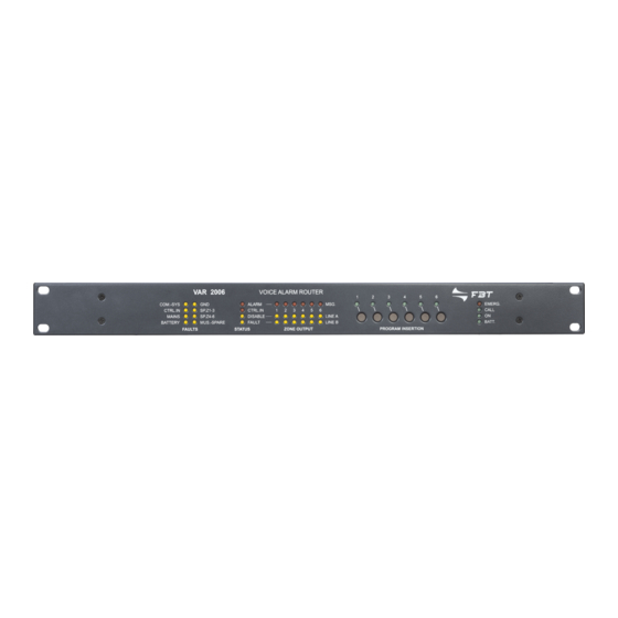
VAR 2006 Router
VAC 2006 Controller
MANUALE DI ISTRUZIONI
OPERATING MANUAL
FBT ELETTRONICA S.p.A. - Via Paolo Soprani, 1 - ZONA IND. SQUARTABUE - 62019 RECANATI (MC) - ITALY
TEL. 071750591 r.a. - FAX 0717505920 - P.O. BOX 104 - E-mail: info@fbt.it - www.fbt.it
Advertisement
Table of Contents

Related Manuals for Fbt VAIE 2000


Summary of Contents for Fbt VAIE 2000
- Page 1 VAC 2006 Controller MANUALE DI ISTRUZIONI OPERATING MANUAL FBT ELETTRONICA S.p.A. - Via Paolo Soprani, 1 - ZONA IND. SQUARTABUE - 62019 RECANATI (MC) - ITALY TEL. 071750591 r.a. - FAX 0717505920 - P.O. BOX 104 - E-mail: info@fbt.it - www.fbt.it...
-
Page 2: Table Of Contents
StAto dI GuASto .....................................57 OPERATIVITÀ E SEGNALAZIONI DEL SISTEMA IN CONDIZIONI DI GUASTO GENERICO ............57 OPERATIVITÀ E SEGNALAZIONI DEL SISTEMA IN CONDIZIONI DI GUASTO LINEE DIFFUSORI ...........57 CARAttERIStICHE tECnICHE ..................................58 VAIE 2000 | Voice Alarm Integrated Systems Manuale di sistema | 2013... - Page 3 AUTOMATIC EMERGENCY – Alarm Condition activated from an external peripheral unit ............112 FAuLt WARnInG CondItIon .................................113 SYSTEM OPERATION AND SIGNALLING IN GENERIC CONDITIONS ..................113 SYSTEM OPERATION AND SIGNALLING IN THE EVENT OF A SPEAkER LINE FAILURE............113 tECHnICAL SPECIFICAtIonS ..................................114 System Manual | 2013 VAIE 2000 | Voice Alarm Integrated Systems...
-
Page 4: Introduzione
1.1 PAnoRAMICA SuL SIStEMA La nuova gamma di prodotti VAIE 2000 è stata progettata e costruita per offrire soluzioni innovative nella realizzazione di sistemi applicati ai servizi d’emergenza. È in grado di gestire le situazioni d’allarme e consentire, in accordo alle norme vigenti (En 54-16, ISo 7240-19 ed En 60849), un’evacuazione guidata e controllata. - Page 5 VAC 2006 • VAR 2006 Controller VAC 2006 ed amplificatori digitali Serie dPu Controller VAC 2006 e router VAR 2006 Sistema VAIE 2000 in configurazione mista Manuale di sistema | 2013 VAIE 2000 | Voice Alarm Integrated Systems...
-
Page 6: Descrizione Generale
R12. Morsettiera per alimentazione esterna in corrente continua 24Vcc. R13. Connessione di terra del telaio. R14. Spina per alimentazione di rete 230Vca con fusibile integrato. Vedi dettagli del pannello comandi a pag. 16. VAIE 2000 | Voice Alarm Integrated Systems Manuale di sistema | 2013... -
Page 7: Router Var 2006
• Prese RJ45 per il collegamento al controller VAC 2006. • 7 contatti d’ingresso programmabili e controllati. • 6 uscite open-collector. • 2 uscite a relè. • Montaggio standard a rack 19” (altezza 1 unità). Manuale di sistema | 2013 VAIE 2000 | Voice Alarm Integrated Systems... -
Page 8: Avvertenze
Nel caso di accidentale caduta di liquidi sull’apparecchio, staccare immediatamente la spina di rete ed interpellare il centro di assistenza FBt più vicino. Nel caso di installazione a rack si prescrive di collegare al telaio del rack la connessione (R13) per mezzo di un cavo più... -
Page 9: Connessioni
VAC 2006 • VAR 2006 ConnESSIonI Manuale di sistema | 2013 VAIE 2000 | Voice Alarm Integrated Systems... -
Page 10: A) Collegamento Tra Controller
B3) Amplificatori Serie dPu. B1) Router VAR 2006 Utilizzare un cavo CAT.5e SF/UTP per collegare le prese ‘SLAVE LINk OUTPUTS’ (R9) alle prese ‘IN/OUT SLAVE LINk’ sul router. VAIE 2000 | Voice Alarm Integrated Systems Manuale di sistema | 2013... - Page 11 B3) Amplificatori Serie dPu Utilizzare cavi CAT.5e SF/UTP per collegare una delle prese ‘SLAVE LINk OUTPUTS’ (R9) alla presa ‘IN/OUT’ dell’amplificatore (DPU 1125C, DPU 1250C o DPU 1500C). Manuale di sistema | 2013 VAIE 2000 | Voice Alarm Integrated Systems...
-
Page 12: C) Collegamento Postazioni D'emergenza
Impostare al Pannello INPUT 2: >MODE: OFF >PH: OFF >I parametri Chime, Priority e Zone list non hanno effetto Attenzione! non collegare altre apparecchiature alla presa MIC dell’ingresso In.2. VAIE 2000 | Voice Alarm Integrated Systems Manuale di sistema | 2013... - Page 13 • MBt 1112: postazione di chiamata a 12 zone. I collegamenti tra VAC 2006 e postazioni microfoniche sono da effettuarsi esclusivamente con cavi di tipo CAT. 5e SF/UTP. Manuale di sistema | 2013 VAIE 2000 | Voice Alarm Integrated Systems...
-
Page 14: E) Contatti D'ingresso Rj45 "Control Inputs
Nota: Nell’esempio, i contatti da 1 a 6 sono controllati, mentre il contatto 7 non lo è. CoLLEGAMEnto ALIMEntAZIonE EStERnA Ai morsetti (R12) è disponibile la connessione per un’alimentazione esterna a 24Vcc. VAIE 2000 | Voice Alarm Integrated Systems Manuale di sistema | 2013... -
Page 15: Operatività E Nomenclatura
- Sorgente sonora collegata all’ingresso IN 3 (Linea) con modalità impostata MODE: ON o VOX. - Postazione d’emergenza (EMERGENCY UNITS) in modalità broadcast, postazione microfonica digitale di chiamata (PAGING UNITS). Durante lo “Stato di Allarme” le sorgenti PA non sono operative. Manuale di sistema | 2013 VAIE 2000 | Voice Alarm Integrated Systems... - Page 16 Sorgente musicale Impostazione fissa Le sorgenti attive in condizione di “Stato d’Allarme” hanno sempre priorità superiore a quelle attive in “Stato di Quiete”, indipendentemente dal livello di priorità impostato. VAIE 2000 | Voice Alarm Integrated Systems Manuale di sistema | 2013...
-
Page 17: Dotazioni E Caratteristiche Funzionali
Ingressi per il collegamento delle postazioni microfoniche di emergenza remote. Utilizzare esclusivamente le postazioni microfoniche FBT FMD 2001 e/o FMD 2012. Prese RJ45 per collegamento con cavo CAT.5e SF/UTP con calza di schermo e connettore schermato STP (per i dettagli di collegamento far riferimento al manuale delle postazioni cod. FBT 37359). Il collegamento delle EMERGENCY UNITS deve essere realizzato a catenella (daisy-chain): le 2 linee di collegamento A e B possono essere lunghe, sommate in totale, fino a 1 km (ognuna). - Page 18 500mAL, del tipo cilindrico da 20mm miniatura, deve essere sostituito solo con un altro di caratteristiche identiche (consultare la sezione “Alimentazione e messa a terra” e “Note di sicurezza” a pag. 8). VAIE 2000 | Voice Alarm Integrated Systems Manuale di sistema | 2013...
- Page 19 Indica che il sistema è in stato d’emergenza. • CALL Indica che è in corso una chiamata broadcast. • ON Indica la presenza dell’alimentazione 230Vca. • BATT. Indica la presenza dell’alimentazione esterna 24Vcc. Manuale di sistema | 2013 VAIE 2000 | Voice Alarm Integrated Systems...
- Page 20 Il collegamento prevede una presa RJ45 con cavo CAT.5e SF/UTP . • n. 6 uscite open collector per il pilotaggio di relè esterni o periferiche generiche. Il sistema VAIE 2000 permette la programmazione delle uscite logiche abbinando l’attivazione dell’uscita ad eventi di stato del sistema o per funzioni di override in emergenza o per la segnalazione dei guasti dell’emergenza in corso e della disabilitazione.
- Page 21 Presa USB alimentata di tipo A, per il collegamento di memorie flash esterne (previsione). C12. Presa uSB “to PC” Presa USB di tipo B, predisposizione per il collegamento del PC di gestione per uso del Software di Sistema. Manuale di sistema | 2013 VAIE 2000 | Voice Alarm Integrated Systems...
-
Page 22: Configurazione Dell'impianto
* In qualsiasi momento è possibile passare alla compilazione di un nuovo progetto selezionando File > New Project; ovviamente, tutti i dati precedentemente inseriti andranno persi, in quanto il programma ripartirà da un progetto vuoto. VAIE 2000 | Voice Alarm Integrated Systems Manuale di sistema | 2013... -
Page 23: Inserimento Dei Controller
Inoltre, può essere indicata la presenza di amplificatori collegati. Una volta impostati i parametri, premere il pulsante End (oppure Cancel per uscire senza salvare le modifiche apportate). Un breve sunto delle impostazioni effettuate sarà disponibile cliccando su LInE 1 > Report. Manuale di sistema | 2013 VAIE 2000 | Voice Alarm Integrated Systems... - Page 24 Una volta impostati i parametri di tutte le linee, passiamo alla compilazione degli altri quattro collegamenti riportati nella finestra principale: CTR INPUT, CTR OUTPUT, EMERGENCY UNITS e BROADCAST UNITS. VAIE 2000 | Voice Alarm Integrated Systems Manuale di sistema | 2013...
- Page 25 ‘Unit key list’. Premere End per salvare la configurazione, oppure Canc. per annullarla e ritornare alla schermata principale. Manuale di sistema | 2013 VAIE 2000 | Voice Alarm Integrated Systems...
- Page 26 Da questa finestra è possibile impostare fino a 64 file di configurazione, che possono poi essere richiamati nelle schermate di configurazione delle postazioni (vedi paragrafi precedenti). VAIE 2000 | Voice Alarm Integrated Systems Manuale di sistema | 2013...
- Page 27 Una volta conclusa la configurazione del CONTROLLER 0, salvare il progetto e cliccare sul tab “CONTROLLER 1” per procedere alla configurazione relativa. Manuale di sistema | 2013 VAIE 2000 | Voice Alarm Integrated Systems...
- Page 28 Terminata la scrittura, estrarre la SD card dal PC ed inserirla nell’apposita slot sul pannello posteriore del CONTROLLER 0; riposizionare il pannellino di copertura e fissarlo nuovamente con le viti precedentemente rimosse. Ripetere queste operazioni per tutti gli altri controller (nel nostro esempio, il CONTROLLER 1). VAIE 2000 | Voice Alarm Integrated Systems Manuale di sistema | 2013...
-
Page 29: Struttura Dei Menu
HOME si potranno selezionare i vari Menu Opzioni per le funzioni avanzate del sistema. Dalla pagina HOME premere il tasto ESC per tornare al Pannello di gestione MUSIC. MEnu Manuale di sistema | 2013 VAIE 2000 | Voice Alarm Integrated Systems... - Page 30 Menu MUSIC o MENU per tornare alla HOME . Per le caratteristiche specifiche di ciascun pannello di gestione del menu oPERAtoR, fare riferimento alle schede relative nella Sezione 8.5 uSo dEL SIStEMA / < Menu oPERAtoR > . VAIE 2000 | Voice Alarm Integrated Systems Manuale di sistema | 2013...
- Page 31 Le caratteristiche funzionali dei pannelli di gestione del menu SERVICE sono di competenza del personale di servizio tecnico ed esulano dagli scopi istruttivi del presente manuale d’uso, pertanto non verranno di seguito illustrate. Manuale di sistema | 2013 VAIE 2000 | Voice Alarm Integrated Systems...
-
Page 32: Uso Del Sistema
• Per il reset del “beep” consultare la Sezione OPERATOR (par. 8.5.3.1, quali è necessaria una password, verranno evidenziate pag. 49) da questo simbolo. • Per l’invio di messaggi d’emergenza consultare la sezione EMERGENZA MANUALE (par. 8.7, pag. 54). VAIE 2000 | Voice Alarm Integrated Systems Manuale di sistema | 2013... -
Page 33: Inizializzazione Dell'impianto
Dopo aver completato la procedura di inizializzazione impianto, effettuare il LOGOUT al fine di ripristinare l’eventuale restrizione di accesso con password (vedi par. 8.5.5, pag. 49). o Percorso: HOME / CONFIGURATION / Exit> Logout (premere tasto Ok). Manuale di sistema | 2013 VAIE 2000 | Voice Alarm Integrated Systems... -
Page 34: Menu
Gli annunci di servizio saranno diffusi al volume impostato per l’ingresso della sorgente PA (vedi menu AUDIO SETTING) e saranno eventualmente inviati anche alle zone con musica disattivata (OFF). VAIE 2000 | Voice Alarm Integrated Systems Manuale di sistema | 2013...Impostazione Dei Parametri Audio Delle Sorgenti Bgm -
Page 35: Menu
è indipendente dalle regolazioni di volume assegnate alle sorgenti. • Caricamento del tono di Chime: Il file audio del Chime è gestito dal software dedicato (vedi pag. 27). Manuale di sistema | 2013 VAIE 2000 | Voice Alarm Integrated Systems... - Page 36 • 6-Phantom: Condizione impostata dell’alimentazione Phantom (OFF=disattiva / ON=attiva). Per cambiare impostazione, premere e rilasciare il tasto 6 (Phantom). I tasti RESET, ALERT, EVAC, MENU ed Ok non sono operativi. Premere ESC per tornare al menu AUDIO SETTING. VAIE 2000 | Voice Alarm Integrated Systems Manuale di sistema | 2013...
- Page 37 • 6-Phantom: Condizione impostata dell’alimentazione Phantom (OFF=disattiva / ON=attiva). Per cambiare impostazione, premere e rilasciare il tasto 6 (Phantom). I tasti RESET, ALERT, EVAC, MENU ed Ok non sono operativi. Premere ESC per tornare al menu AUDIO SETTING. Manuale di sistema | 2013 VAIE 2000 | Voice Alarm Integrated Systems...
-
Page 38: Menu
LED). < oPERAtoR > Passaggio diretto al menu OPERATOR vedere par. 8.5, pag. 46. < ConFIGuRAtIon > Passaggio diretto al menu CONFIGURATION vedere par. 8.6, pag. 50. VAIE 2000 | Voice Alarm Integrated Systems Manuale di sistema | 2013... - Page 39 2006 spegne automaticamente il buzzer, spegne il Led FAULT e riporta la scritta RES (Resumed) nell’etichetta dell’elemento che era in FAULT . La segnalazione di Resumed rimarrà in memoria fino a quando verrà effettuato il RESET MANUALE della segnalazione di guasto accedendo al pannello FAULTS da Menu OPERATOR. Manuale di sistema | 2013 VAIE 2000 | Voice Alarm Integrated Systems...
- Page 40 Per ogni elemento sorvegliato viene segnalato lo stato di diagnosi come da seguente tabella. Per accedere ai sub-pannelli, premere i tasti numerici corrispondenti. Premere ESC per tornare al pannello FAULTS. VAIE 2000 | Voice Alarm Integrated Systems Manuale di sistema | 2013...
- Page 41 “LINK FAULTS”. Verificare i cavi di Intercomunicazione con 6-Remote Link Fault collegamento fra i VAC 2006 per la connessione VAC 2006 remoti VAC 2006 LINK. Se il guasto permane, contattare l’Assistenza. Tab. 8.4.1.3 Manuale di sistema | 2013 VAIE 2000 | Voice Alarm Integrated Systems...
- Page 42 5240/48 collegati al router Gnd Fault Verificare le connessioni delle linee Verifica l’isolamento tra le altoparlanti. Se il guasto permane, contattare linee altoparlanti e la terra. l’Assistenza. Tab. 8.4.1.4 VAIE 2000 | Voice Alarm Integrated Systems Manuale di sistema | 2013...
- Page 43 Ctr display Display del controller Fault Rilevata anomalia sul display Contattare l’Assistenza. VAIE display Display del VAIE 2250 Fault Rilevata anomalia sul display Contattare l’Assistenza. Tab. 8.4.1.5 Manuale di sistema | 2013 VAIE 2000 | Voice Alarm Integrated Systems...
- Page 44 Se la percentuale di variazione supera il valore di tolleranza impostato in fase di configurazione impianto, verrà segnalato il guasto “LOUDSPk LINE FAULT” per impedenza troppo alta o troppo bassa (Impedance Hi o Impedance Low). Premere ESC per tornare al pannello INSPECTION. VAIE 2000 | Voice Alarm Integrated Systems Manuale di sistema | 2013...
- Page 45 BEEP di avvertimento. Verificare l’operatività dell’altoparlante a bordo, di tutti i LED e di tutti i pixel del display. In caso di malfunzionamento contattare l’Assistenza. Premere ESC per tornare al pannello INSPECTION. Manuale di sistema | 2013 VAIE 2000 | Voice Alarm Integrated Systems...
-
Page 46: Menu
< ConFIGuRAtIon > Passaggio diretto al menu CONFIGURATION. 8.5.5 opzione Exit > Logout Uscita dal livello di servizio e ritorno al livello base con ripristino della password di accesso. VAIE 2000 | Voice Alarm Integrated Systems Manuale di sistema | 2013... - Page 47 > 1-Remote link A > 2-Remote link B > 3-Remote ctr Nota: il display visualizza lo stato di programmazione impostato. Premere ESC per tornare al pannello BACkGROUND TEST. Manuale di sistema | 2013 VAIE 2000 | Voice Alarm Integrated Systems...
- Page 48 > 1-Communication (on = test abilitato / off = test disabilitato) Nota: il display visualizza lo stato di programmazione impostato. Premere ESC per tornare al pannello BACkGROUND TEST. VAIE 2000 | Voice Alarm Integrated Systems Manuale di sistema | 2013...
- Page 49 Il sistema torna al Livello Base e visualizza il pannello del Menu MUSIC. La richiesta della password di accesso sarà ripristinata anche per gli altri livelli che eventualmente erano stati visitati. Manuale di sistema | 2013 VAIE 2000 | Voice Alarm Integrated Systems...
-
Page 50: Menu
< SERVICE > Collegamento al menu SERVICE dedicato al personale tecnico fornito di opportuna chiave d’accesso, per la modifica dei parametri di funzionamento del sistema VAC 2006, aggiornamento firmware e assistenza tecnica. nota: le impostazioni del menu Service non verranno trattate nel presente Manuale. VAIE 2000 | Voice Alarm Integrated Systems Manuale di sistema | 2013... - Page 51 0% (Not Tested). Premere ESC per tornare al menu CONFIGURATION. Al termine della procedura, effettuare eventualmente il RESET MANUALE DELLA SEGNALAZIONE DI GUASTO come descritto nel par.8.5.3.1, pag. Manuale di sistema | 2013 VAIE 2000 | Voice Alarm Integrated Systems...
- Page 52 > 6-Line 2 level >Premere tasto 6 e ruotare la manopola +/- Nota: il display visualizza lo stato di programmazione impostato in fabbrica. Premere ESC per tornare al pannello 20kHZ LEVEL SETTINGS. VAIE 2000 | Voice Alarm Integrated Systems Manuale di sistema | 2013...
- Page 53 • Utilizzare il tasto 1 per abilitare o disabilitare l’emissione del segnale sonoro. nota: il display visualizza lo stato di programmazione impostato. Al termine dell’operazione premere ESC per tornare al menu CONFIGURATION. Manuale di sistema | 2013 VAIE 2000 | Voice Alarm Integrated Systems...
-
Page 54: Emergenza Manuale - Menu
Per terminare il messaggio d’emergenza in vivavoce, rilasciare il pulsante P.T.T. e premere nuovamente il pulsante EMERGEnCY, avendo cura di richiudere lo sportellino. VAIE 2000 | Voice Alarm Integrated Systems Manuale di sistema | 2013... - Page 55 Emergenza Automatica, visualizzando il Menu INPUT ALARM STATUS e riprendendo la diffusione dei messaggi di emergenza in base alla programmazione prevista per gli ingressi attivati, con eventuale Led ALARM acceso ad indicare la condizione di VOICE ALARM attiva. Manuale di sistema | 2013 VAIE 2000 | Voice Alarm Integrated Systems...
-
Page 56: Emergenza Automatica - Stato Di Allarme Attivato Da Periferica Esterna
Al fine di segnalare all’operatore che l’attivazione dell’allarme proviene da contatti esterni, il controller mantiene visualizzato sul display l’avviso dell’avvenuta emergenza (lampeggiante). Il sistema torna allo Stato di quiete visualizzando il pannello MUSIC. VAIE 2000 | Voice Alarm Integrated Systems Manuale di sistema | 2013... -
Page 57: Stato Di Guasto
Manuale di sistema | 2013 VAIE 2000 | Voice Alarm Integrated Systems... -
Page 58: Caratteristiche Tecniche
Dimensioni prodotto (L x A x P) 482 x 44 x 220 mm Dimensioni imballo (L x A x P) 522 x 155 x 292 mm Peso netto 4 kg Peso lordo 5 kg VAIE 2000 | Voice Alarm Integrated Systems Manuale di sistema | 2013... - Page 59 Disabillitazione dell’allarme vocale in determinate zone/a Controllo manuale degli allarmi vocali Interfaccia per dispositivi di controllo esterni Microfono d’emergenza 13.14 Amplificatori di riserva LIStA dELLE FunZIonI AuSILIARIE Chiamate broadcast Musica di sottofondo Manuale di sistema | 2013 VAIE 2000 | Voice Alarm Integrated Systems...
-
Page 60: Introduction
1.1 SYStEM oVERVIEW The new VAIE 2000 product range has been designed and manufactured in order to offer innovative solutions for making systems applied to emergency services. It is capable of managing alarm situations and of enabling guided and controlled evacuation, in accordance with the applicable standards (En 54-16, ISo 7240-19 and En 60849). - Page 61 VAC 2006 • VAR 2006 VAC 2006 controllers and digital amplifiers of the dPu range VAC 2006 controller and VAR 2006 router VAIE 2000 | System featuring a mixed configuration System Manual | 2013 VAIE 2000 | Voice Alarm Integrated Systems...
-
Page 62: General Description
R11. 3 relay outputs for signalling towards external peripheral units. R12. Terminals for 24 VDC external power supply. R13. Frame earthing connection. R14. Plug for 230 VAC mains power supply, with built-in fuse. See details on page 76. VAIE 2000 | Voice Alarm Integrated Systems System Manual | 2013... -
Page 63: Var 2006 Router
• RJ45 sockets for connection to the VAC 2006 controller. • 7 programmable and controlled input contacts. • 6 open-collector outputs. • 2 relay outputs. • Can be mounted in a standard 19” rack (height: 1 unit). System Manual | 2013 VAIE 2000 | Voice Alarm Integrated Systems... -
Page 64: Warnings
If any liquid is accidentally spilt onto the equipment, unplug it immediately from the mains and contact the nearest FBt Service Centre. In case of rack installation, it is required to connect the (R13) connection to the to rack frame by means of a cable as short as possible (about 20cm). -
Page 65: Connections
VAC 2006 • VAR 2006 ConnECtIonS System Manual | 2013 VAIE 2000 | Voice Alarm Integrated Systems... -
Page 66: A) Connection Among Controllers
B3) Amplifiers of the dPu range. B1) VAR 2006 router Use Cat.5e SF/UTP cables to connect the ‘SLAVE LINk OUTPUTS’ sockets (R9) to the ‘IN/OUT SLAVE LINk’ sockets on the router. VAIE 2000 | Voice Alarm Integrated Systems System Manual | 2013... - Page 67 Use a Cat.5e SF/UTP cable to connect one of the ‘SLAVE LINk OUTPUTS’ sockets (R9) to the ‘IN/OUT’ socket on the amplifier (DPU 1125C, DPU 1250C or DPU 1500C). System Manual | 2013 VAIE 2000 | Voice Alarm Integrated Systems...
-
Page 68: C) Connecting The Emergency Stations
> PH: OFF > The Chime, Priority and Zone List parameters have no effect. Caution! do not connect any other equipment to the MIC socket of the In.2 input. VAIE 2000 | Voice Alarm Integrated Systems System Manual | 2013... - Page 69 • MBt 1106: 6-zone paging unit. • MBt 1112: 12-zone paging unit. N.B.: The connections between the VAC 2006 and PAGING UNITS must be made solely with CAT. 5e SF/UTP. System Manual | 2013 VAIE 2000 | Voice Alarm Integrated Systems...
-
Page 70: E) Rj45 Input Contacts "Control Inputs
N.B.: In the example, contacts 1 to 6 are controlled while contact 7 is not. ConnECtInG An EXtERnAL PoWER SuPPLY A connection for a 24 VDC outside power supply is available on the terminals provided (R12). VAIE 2000 | Voice Alarm Integrated Systems System Manual | 2013... -
Page 71: Operating Conditions And Terminology
- Source of sound connected to the IN 2 input (Microphone or Line input), set in the ON, VOX or PRECEDENCE MODES. - EMERGENCY UNIT in the broadcasting mode, PAGING UNITS. During a “Voice Alarm Condition” the PA sources are not operational. System Manual | 2013 VAIE 2000 | Voice Alarm Integrated Systems... - Page 72 See the manual of MBT 1106 & MBT 1112 stations Music source Fixed setting Source The active sources in the “Voice Alarm” condition always have priority over those active in “Quiescent” condition, regardless of the priority level set. VAIE 2000 | Voice Alarm Integrated Systems System Manual | 2013...
-
Page 73: Equipment And Functional Specifications
Cat. 5e SF/UTP cable with a shielding braid and shielded STP connector (for details of the connection, consult the manual of the FBT 37359 stations). The EMERGENCY UNITS must be connected to one another in daisy-chain fashion: each of the two connecting lines A and B can reach a total length of up to 1 km. - Page 74 500 mA fuse, of the miniature 20 mm cylindrical type. (consult the “Power supply and earthing” and “Safety Notes” sections on page 64 for details about safety). VAIE 2000 | Voice Alarm Integrated Systems System Manual | 2013...
- Page 75 This indicates that a broadcast call is being sent out. • ON This indicates the presence of the 230 VAC power supply. • BATT. This indicates the presence of the 24 VDC external power supply. System Manual | 2013 VAIE 2000 | Voice Alarm Integrated Systems...
- Page 76 In the idle condition, this key is not operational. VAIE 2000 | Voice Alarm Integrated Systems System Manual | 2013...
- Page 77 Powered type A USB socket for connecting external flash memory devices (for future use). C12. “to PC” uSB socket Type B USB socket, provisions for connecting the management PC in order to use the system software. System Manual | 2013 VAIE 2000 | Voice Alarm Integrated Systems...
-
Page 78: Configuration Of The System
* It is possible at any time to compile a new project by selecting File > New Project. Of course all the previously entered data will be lost since the programme will start again from an empty project. VAIE 2000 | Voice Alarm Integrated Systems System Manual | 2013... -
Page 79: Inserting The Controllers
You can also indicate the presence of amplifiers connected to it. Once you have set the parameters, press End (or Cancel to exit without saving the changes made). You can find a brief summary of the settings made by clicking on LInE 1 > Report. System Manual | 2013 VAIE 2000 | Voice Alarm Integrated Systems... - Page 80 1 onwards (max 16 for each line). to set the address of each single amplifier, consult the “Settings” section in the instruction booklet of the DPU range (FBt code number 37784).
- Page 81 “Configuring groups of zones”) or to make changes manually to the default configuration prompted in the ‘Unit key list’ box. Press End to save the configuration, or press Canc. to cancel it and return to the main window. System Manual | 2013 VAIE 2000 | Voice Alarm Integrated Systems...
- Page 82 In this window, you can set up to 64 configuration files, which you can call up in the configuration windows of the stations (see previous sections). VAIE 2000 | Voice Alarm Integrated Systems System Manual | 2013...
- Page 83 Canc. to cancel it and return to the main window. Once you have completed configuring CONTROLLER 0, save the project and click on the “CONTROLLER 1” tab to proceed with its configuration. System Manual | 2013 VAIE 2000 | Voice Alarm Integrated Systems...
- Page 84 Once writing has been completed, remove the SD card from the PC, then plug it into its slot in the rear panel of CONTROLLER 0. Put the cover back into place and fix it with the screws removed earlier. Repeat these operations for all the other controllers (in the example, CONTROLLER 1). VAIE 2000 | Voice Alarm Integrated Systems System Manual | 2013...
-
Page 85: Menu Structure
HOME page it will be possible to select the various different Option Menus for the advanced functions of the system. From the HOME page, press ESC to return to the MUSIC management panel. MEnu System Manual | 2013 VAIE 2000 | Voice Alarm Integrated Systems... - Page 86 MUSIC menu or MENU to return to the HOME page. For the specific features for each panel for managing the oPERAtoR menu, refer to the appropriate schedules in Section 8. USING tHE SYStEM / 8.5 < oPERatoR Menu >. VAIE 2000 | Voice Alarm Integrated Systems System Manual | 2013...
- Page 87 The Functional Specifications of the panels for managing the SERVICE menu are the responsibility of the Service personnel and beyond the scope of this User Manual. They are therefore not illustrated here. System Manual | 2013 VAIE 2000 | Voice Alarm Integrated Systems...
-
Page 88: Using The System
The functions associated with levels featuring restricted access, for which a password may be set, • To send emergency messages, consult the MANUAL EMERGENCY are highlighted by this symbol. Section (point 8.7, page 110). VAIE 2000 | Voice Alarm Integrated Systems System Manual | 2013... -
Page 89: Initialising The System
After completing the system initialisation procedure, LOG OUT in order to reinstate any access restrictions associated with passwords (point 8.5.5, page 105). o Path: HOME / CONFIGURATION / Exit> Logout (press the Ok key). System Manual | 2013 VAIE 2000 | Voice Alarm Integrated Systems... -
Page 90: Music> Menu
Service announcements will be broadcast at the volume set for the input of the PA Source (see AUDIO SETTINGS menu) and if appropriate will also be sent to the zones for which music is de-activated (OFF). VAIE 2000 | Voice Alarm Integrated Systems System Manual | 2013... -
Page 91: Audio Setting> Menu
Hold down key 1 and use the +/- knob to adjust the volume within the range from 0 to 255; the volume is common to all four inputs and is separate from the volume adjustment assigned to the sources. • Loading the Chime tone: The Chime audio file is managed by the dedicated software (see page 83). System Manual | 2013 VAIE 2000 | Voice Alarm Integrated Systems... - Page 92 • 6-Phantom: Setting of the Phantom power supply (OFF = not active / ON = active). To change the setting, press key 6 (Phantom), then release The RESET, ALERT, EVAC, MENU and Ok have no functions. Press ESC to return to the AUDIO SETTINGS menu. VAIE 2000 | Voice Alarm Integrated Systems System Manual | 2013...
- Page 93 • 6-Phantom: Setting of the Phantom power supply (OFF = not active / ON = active). To change the setting, press key 6 (Phantom), then release The RESET, ALERT, EVAC, MENU and Ok have no functions. Press ESC to return to the AUDIO SETTINGS menu. System Manual | 2013 VAIE 2000 | Voice Alarm Integrated Systems...
-
Page 94: Inspection> Menu
For checking the functionality of the signalling elements connected with the emergency (buzzer loudspeaker, display and LEDs) < oPERAtoR > Passaggio diretto al menu OPERATOR (point 8.5, page 102). < ConFIGuRAtIon > Passaggio diretto al menu CONFIGURATION (point 8.6, page 106). VAIE 2000 | Voice Alarm Integrated Systems System Manual | 2013... - Page 95 FAULT LED and indicate RES (RESUMED) in the label of the part that had FAILED. The RESOLVED signal will be stored until a MANUAL RESET of the failure signal is carried out from the FAULTS panel via the OPERATOR menu. System Manual | 2013 VAIE 2000 | Voice Alarm Integrated Systems...
- Page 96 For some items of equipment it may be necessary to access the sub-panel, by pressing the corresponding numbered key. Press ESC to return to the panel FAULTS. VAIE 2000 | Voice Alarm Integrated Systems System Manual | 2013...
- Page 97 Intercommunication with between the VAC 2006 units for connection 6-Remote Link Fault remote VAC 2006 units VAC 2006 LINk. If the failure persists, contact the Service Centre. Tab. 8.4.1.3 System Manual | 2013 VAIE 2000 | Voice Alarm Integrated Systems...
- Page 98 Centre. Gnd Fault Check the connections of the loudspeaker Check the insulation between lines. If the failure persists, contact the the loudspeaker lines and Service Centre. earth. Tab. 8.4.1.4 VAIE 2000 | Voice Alarm Integrated Systems System Manual | 2013...
- Page 99 Ctr display Controller display Fault Upset detected on display Contact the Service Centre. VAIE display VAIE 2250 display Fault Upset detected on display Contact the Service Centre. Tab. 8.4.1.5 System Manual | 2013 VAIE 2000 | Voice Alarm Integrated Systems...
- Page 100 If the percentage of variation exceeds the level of tolerance set at the time of configuring the system, a “LOUDSPk LINE FAULT” due to an excessively high or low impedance (Impedance Hi or Impedance Low) will be signalled. Press ESC to return to the INSPECTION panel. VAIE 2000 | Voice Alarm Integrated Systems System Manual | 2013...
- Page 101 (BEEP) will sound for about three seconds. The functionality of the built-in speaker, all LEDs and all the display pixels are checked. Please contact Support in case of failure. Press ESC to return to the INSPECTION panel. System Manual | 2013 VAIE 2000 | Voice Alarm Integrated Systems...
-
Page 102: Operator> Menu
< ConFIGuRAtIon > For going directly to the CONFIGURATION menu. 8.5.5 Exit > Logout option To exit from the service level and return to the basic level, reinstating the access password. VAIE 2000 | Voice Alarm Integrated Systems System Manual | 2013... - Page 103 > 1-Remote link A > 2-Remote link B > 3-Remote ctr Note: The display will show the programming that has been set. Press ESC to return to the BACkGROUND TEST panel. System Manual | 2013 VAIE 2000 | Voice Alarm Integrated Systems...
- Page 104 > 1-Communication (on = test enabled / off = test disabled) Note: The display will show the programming that has been set. Press ESC to return to the BACkGROUND TEST panel. VAIE 2000 | Voice Alarm Integrated Systems System Manual | 2013...
- Page 105 The system will return to the Basic Level, showing the MUSIC Menu panel. The prompt requiring the access password to be entered will also be rein- stated for any other levels that had been reached. System Manual | 2013 VAIE 2000 | Voice Alarm Integrated Systems...
-
Page 106: Configuration Menu
< SERVICE > Connection to the SERVICE menu for technical personnel having the necessary password. It is used to change the operating parameters of the VAC 2006 system, up-dating the firmware and servicing it. note: The settings of the Service Menu are not covered in this Manual. VAIE 2000 | Voice Alarm Integrated Systems System Manual | 2013... - Page 107 Press ESC to return to the CONFIGURATION menu. Upon completion of the procedure, if appropriate carry out a MANUAL RESET OF THE FAILURE SIGNALLING as described under point 8.5.3.1, page 105. System Manual | 2013 VAIE 2000 | Voice Alarm Integrated Systems...
- Page 108 > 6-Line 6 level > Press key 6 then turn the +/- knob. N.B.: The display shows the status of the factory-set programming. Press ESC to return to 20kHZ LEVEL SETTINGS panel. VAIE 2000 | Voice Alarm Integrated Systems System Manual | 2013...
- Page 109 • Use key 1 to enable or disable emission of the acoustic signal. nota: The display shows the status of the set programming. Upon completion, press ESC to return to the CONFIGURATION menu. System Manual | 2013 VAIE 2000 | Voice Alarm Integrated Systems...
-
Page 110: Manual Emergency -
To end live emergency messages, release the PTT key, then press the EMERGEnCY push-button again. Make sure that you close the lid again. VAIE 2000 | Voice Alarm Integrated Systems System Manual | 2013...Menu - Page 111 Automatic Emergency mode, displaying the INPUT ALARM STATUS menu. Broadcasting of the emergency messages will resume as programmed for the inputs that have been activated, and the ALARM LED will light up, if appropriate, to indicate activation of a VOICE ALARM. System Manual | 2013 VAIE 2000 | Voice Alarm Integrated Systems...
-
Page 112: Automatic Emergency - Alarm Condition Activated From An External Peripheral Unit
To inform the operator that the alarm was activated via external contacts, the controller keeps the notice of the emergency flashing on the display. The system will return to a “quiescent Condition” showing the MUSIC panel. VAIE 2000 | Voice Alarm Integrated Systems System Manual | 2013... -
Page 113: Fault Warning Condition
If it is due to a short circuit on the line, the system will disconnect the failed line and broadcast the audio signal on the other line serving the same zone. System Manual | 2013 VAIE 2000 | Voice Alarm Integrated Systems... -
Page 114: Technical Specifications
Size of unit (L x H x D) 482 x 44 x 220 mm Size of package (L x H x D) 522 x 155 x 292 mm Net weight 4 kg Gross weight 5 kg VAIE 2000 | Voice Alarm Integrated Systems System Manual | 2013... - Page 115 Indication of faults related to voice alarm zones Disablement condition Voice alarm manual control Interface to external control device(s) Emergency microphone(s) 13.14 Redundant power amplifiers LISt oF AuXILIARY FunCtIonS Broadcast calls Background music System Manual | 2013 VAIE 2000 | Voice Alarm Integrated Systems...
- Page 116 Le informazioni contenute in questo manuale sono state scrupolosamente controllate; tuttavia non si assume nessuna responsabilità per eventuali inesattezze. La FBT Elettronica S.p.A. si riserva il diritto di modificare le caratteristiche tecniche ed estetiche dei prodotti in qualsiasi momento e senza preavviso.