
Related Manuals for Cateye ERGOCISER EC-3600


Summary of Contents for Cateye ERGOCISER EC-3600
- Page 1 CATEYE ERGOCISER AUTOMATIC TYPE Applicable Models: EC-1200/EC-1600/EC-3600/EC-3700 SERVICE MANUAL...
-
Page 2: Table Of Contents
• Name of Parts 1. Upright Type (w/o Flywheel) ---------------------------------------------------------- 4~5 Upright Type (with Flywheel) --------------------------------------------------------- 6~7 2. Recumbent Type (EC-3600 & EC-3700) ------------------------------------------- 8~9 3. Belt Drive (EC-1200B, EC-1600B, EC-3600B & EC-3700B) ---------- ADD.1~2 • Circuit Diagram ---------------------------------------------------------------------------------- 10 Part A Symptoms of Problems &... -
Page 3: How To Use This Service Manual
2. Identify the parts name by referring to Name of Parts. 3. Perform repair or adjustment in accordance with the instructions in Part B. 4. Replacement, if required, should be done by using genuine parts as specified in Part C. Cateye Ergociser Series 1000 Service Manual... -
Page 4: Name Of Parts
5P Cable Connector CDC Sensor Frame Leg Cover Leg Pipe Leg Pipe Fixing Screw Caster Levelling Knob Cateye Ergociser Series 1000 Service Manual EC-1200 EC-1600 EC-3600 EC-3700 Crank Crank Cap BB Set Adjust Screw Spacer Spring SW Nut (M6) Power Supply Board... - Page 5 Fixing Bolt Derailleur Mounting Bolt Free Wheel Set Levelling Knob Thrust Washer (9x15.5x0.25) Hexagon Head U Nut Derailleur Applicable Models: EC-1200 EC-1600 EC-3600 EC-3700 Crank Nut Power Supply Board Solenoid Coil Cateye Ergociser Series 1000 Service Manual Screw Set(+) (M6x16)
-
Page 6: Upright Type (W/O Flywheel)
Cable Holder Large Gear CDC Magnet CDC Sensor Frame Caster Leg Pipe Fixing Screw Leg Pipe Cateye Ergociser Series 1000 Service Manual EC-1200 EC-1600 EC-3600 EC-3700 5P Cable Connector Lock Nut Flywheel Mounting Metal Base BB Set Crank Cap Crank... - Page 7 Solenoid Coil Derailleur Mounting Bolt Thrust Washer (9x15.5x0.25) Derailleur EC-1200 EC-1600 EC-3600 EC-3700 Handlebar Post Cover Seat Post Center Cover Frame Cover Crank Cover Tapping Screw (4x12) with Washer Crank Nut (M10x1.25) Screw Set(+) (M6x16) Cateye Ergociser Series 1000 Service Manual...
- Page 8 Applicable Models: Name of Parts for Recumbent Type (EC-3600 & EC3700) Wiring within Frame Flywheel Metal Base Fixing Screw Flywheel Flywheel Fixing Screw Flywheel Metal Base Plain Belt Frame Cover Center Cover Crank Cover Inner Pipe Cateye Ergociser Series 1000 Service Manual...
- Page 9 EC-1200 EC-1600 EC-3600 EC-3700 Power Supply Board CDC Magnet Cable Holder Flywheel Plain Belt Flywheel Fixing Screw Flywheel Metal Base Fixing Screw Inlet Metal Base AC Adapter Inlet Power Switch Front Leg with Casters Caster Cateye Ergociser Series 1000 Service Manual...
-
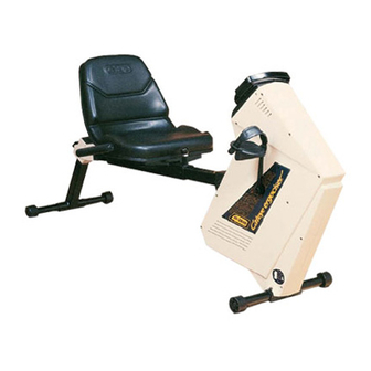
Page 10: Recumbent Type (Ec-3600 & Ec-3700)
Pulley 1-A Set Pulley Flange Pulley Flange Pulley 2-A Set Pulley 2-A Set Pulley 1-B Idler A Set Pulley 1-B Idler A Set Workload Unit Idler Spring A Workload Unit Idler Spring A Cateye Ergociser Series 1000 Service Manual ADD. 1... - Page 11 Applicable Models: EC-3600B/EC-3700B Belt Drive Pulley 1-A Set Pulley Flange EC-3600B/EC-3700B Teethed Timing Belt (P8M15-1080) Pulley 2-A Set Pulley 1-B Idler A Set Workload Unit Idler Spring A Cateye Ergociser Series 1000 Service Manual ADD. 2...
- Page 12 Applicable Models: Circuit Diagram for Automatic Type Cateye Ergociser AC Plug DC Power Supply Cateye Ergociser Series 1000 Service Manual EC-1200 EC-1600 EC-3600 EC-3700 AC Adapter 100V AC 12V DC* DC Connector *Fluctuate depending on the electric load About 16V when the load is zero.
- Page 13 Explanation Figures Normal for 14V thru 19V Red Cable DC Connector Cable Connector Black Cable Fig. 2 Normal for 14V thru 19V Black Cable Red Cable Terminal 3 (+) 5P Cable Terminal 1 (-) Cateye Ergociser Series 1000 Service Manual...
-
Page 14: Removing The Frame Covers
When the problem cannot be remedied even if the 5P cable is replaced, the power supply board may be defective. Cateye Ergociser Series 1000 Service Manual EC-1200 EC-1600 EC-3600 EC-3700 Repair Method Replace the 5P cable. (See the Section ES-2 "Replacing the Frame.") -
Page 15: No Display Of Cadence
Red Cable CN-3 Connector Fig. 3 Gap of 2mm between CDC Sensor and CDC Magnet Line on CDC Sensor Line on CDC Sensor Center of CDC Magnet Fig. 5 Cateye Ergociser Series 1000 Service Manual Terminal 2 Terminal 1 Black Cable... -
Page 16: No Display Of Pulse Rate
When the pulse rate can be displayed, the pulse sensor is defective. When the pulse rate cannot be displayed, the control unit is defective. Cateye Ergociser Series 1000 Service Manual EC-1200 EC-1600 EC-3600 EC-3700 Repair Method Replace the pulse sensor with a brand new one. -
Page 17: No Printer Operation
TIME MODE Back of Control Unit Fig. 2 Cable Connector Fig. 4 Normal when zero (0) Power Supply Board Connector Terminal 5 5P Cable Connector Terminal 5 Fig. 6 Cateye Ergociser Series 1000 Service Manual 1 2 3 Select Switch... -
Page 18: No Loading
(Fig. 2) 5. Check if the plastic pulley of the workload unit has not been broken. (Fig. 2) Cateye Ergociser Series 1000 Service Manual EC-1200 EC-1600 EC-3600 EC-3700 Repair Method Replace the chain with a brand new one. (See the Section MS-4 "Replacing the Chain.") - Page 19 Fig. 5 Applicable Models: EC-1200 EC-1600 EC-3600 EC-3700 Explanation Figures Power Supply Board CN-2 Connector Fig. 2 CN-1 Connector Fig. 4 5P Cable Connector Terminal 4 Connector Terminal 2 To Solenoid Coil CN-1 Connector Cateye Ergociser Series 1000 Service Manual...
-
Page 20: No Pedal Rotation (Locked)
2. Check if the plain belt of the flywheel has not been detached. (Fig. 1) No damage on the plain belt The plain belt is damaged. Cateye Ergociser Series 1000 Service Manual EC-1200 EC-1600 EC-3600 EC-3700 Repair Method Apply the plain belt correctly. (See the Section MS-2 "Replacing the Workload Unit (w/ Flywheel).") -
Page 21: Unusual Noise
Fig. 1 Timing Belt Fig. 2 Applicable Models: EC-1200 EC-1600 EC-3600 EC-3700 Explanation Figures Chain Derailleur Idler Idler Set Plain Belt Plastic Pulley Fig. 3 Cateye Ergociser Series 1000 Service Manual... -
Page 22: Periodical
Remove the frame cover, and check the inside of frame. (See the Sections D-1 & D-2 "Removing the Frame Covers.") The copper disc plate of the workload unit may touch the solenoid coil. (Figs. 2 & 3) Cateye Ergociser Series 1000 Service Manual EC-1200 EC-1600 EC-3600 EC-3700 Repair Method No.15 Wrench Use a No.15 wrench and securely fasten the pedal to... -
Page 23: Noise Occurs When The Pedal Is Rotated With A Large Loading
Hook the idler spring on the pawl of the idler. Securely fasten the idler mounting bolt. Idler Spring Fig. 1 Applicable Models: EC-1200 EC-1600 EC-3600 EC-3700 Explanation Figures Idler Pawl Idler Mounting Bolt dler Metal Base Cateye Ergociser Series 1000 Service Manual... -
Page 24: Removing The Frame Covers
7. Fix the leg pipe with the leg pipe fixing screws. (For the model EC-1600, mount the leg pipe cover.) Cateye Ergociser Series 1000 Service Manual EC-1200 EC-1600 EC-3600 EC-3700 No. 15 Wrench Crank... -
Page 25: Recumbent Type (Ec-3600 & Ec-3700)
Removing the Frame Covers Recumbent Type (EC-3600 & EC-3700) When any repair or adjustment of parts within the frame is required, remove the frame covers in the following procedures. REMOVAL 1. Remove the pedals at both the left and right sides. (The right... -
Page 26: Replacing The Wiring Within The Frame
(Fig. 3) 6. Provisionally connect the control unit, and check the unit works fine after turning on the power. Then, completely assemble the frame cover. Cateye Ergociser Series 1000 Service Manual EC-1200 EC-1600 EC-3600 EC-3700 Inlet Metal Base Power Supply Board EC-1200 &... -
Page 27: Replacing The 5P Cable
Cable Holder Handlebar Stem Cover Screws Fig. 7 Fig. 8 Applicable Models: EC-1200 EC-1600 EC-3600 EC-3700 Unit-Side Cable Connector Mark this point. 87cm Fig. 3 Inner Handlebar Post Cover Cable Unplug Connector Screws Fig. 6 Cateye Ergociser Series 1000 Service Manual... -
Page 28: Replacing The 5P Cable
4. Mount the frame cover to restore the original shape. (See the Section D-1 "Removing the Frame Covers.") Recumbent Type (EC-3600 and EC-3700) Removing the Existing Cable 1. Loosen the four screws which fix the control unit to remove the control unit. -
Page 29: Replacing The Power Supply Board
Power Supply Board B Power Supply Board A Fig. 4 Fig. 3 Applicable Models: EC-1200 EC-1600 EC-3600 EC-3700 EC-3600 & EC-3700 Solenoid Coil COIL K6020 LOT No. Location of Coil Current Value Indication Fig. 5 Cateye Ergociser Series 1000 Service Manual... -
Page 30: Correcting The Position Of Solenoid Coil
[2] In case correction is not possible by the method stated in [1]. Replace the whole workload unit. (See the Section MS-2 "Replacing the Workload Unit (w/ Flywheel).") Cateye Ergociser Series 1000 Service Manual EC-1200 EC-1600 EC-3600 EC-3700 Workload Unit... -
Page 31: Replacing The Cdc Sensor
Center of CDC Magnet Line on CDC Sensor Fig. 4 Fig. 3 Applicable Models: EC-1200 EC-1600 EC-3600 EC-3700 CDC Sensor EC-3600 & EC-3700 CDC Sensor Cable Holders Center of CDC Magnet Fig. 5 Cateye Ergociser Series 1000 Service Manual Power Supply Board... -
Page 32: Replacing The Panel Keyboard
9. Put the upper and lower body together, and fix them with eight screws. 10. Connect the cable connector to the control unit, and mount the unit to the main unit. Cateye Ergociser Series 1000 Service Manual EC-1200 EC-1600 EC-3600 EC-3700 Control Unit Screw Cable Connector Fig. -
Page 33: Replacing The Button Panel
2. Clean the adhesive agent, if any, on the control unit before placing a brandnew button panel. * Sufficiently press the button panel thus placed. Button Panel Control Unit Fig. 1 Applicable Models: EC-1200 EC-1600 EC-3600 EC-3700 Cateye Ergociser Series 1000 Service Manual... -
Page 34: Replacing The Printer
7. Adjust the printing darkness by referring to the Section ES-9 "Adjusting the Printing Darkness." 8. Mount the control unit to the main unit. Cateye Ergociser Series 1000 Service Manual EC-1200 EC-1600 EC-3600 EC-3700 Printer Unit Printer Fixing Screws Fig. -
Page 35: Adjusting The Printing Darkness
NOTE: Never touch the potentiometer DCV. Upright Type Recumbent Type Control Unit Cable Connector Fig. 1 Fig. 2 Potentiometer PR Fig. 3 Applicable Models: EC-1200 EC-1600 EC-3600 EC-3700 Control Unit Cable Connector Cateye Ergociser Series 1000 Service Manual... -
Page 36: Paper Jamming In Printer
3. Assemble the control unit by referring to the Section ES-6 "Replacing the Panel Keyboard (9) & (10)." 4. Set the printer paper. (See the Operation Manual.) Cateye Ergociser Series 1000 Service Manual EC-1200 EC-1600 EC-3600 EC-3700 Pincette Printer Unit... -
Page 37: Replacing The Workload Unit (W/O Flywheel) (1
Fig. 1 Workload Unit Reinforcing Metal Base Cable Holder Fig. 2 Fig. 3 Workload Unit Workload Unit Fixing Hexagon Head Bolt Fig. 4 Applicable Models: EC-1200 EC-1600 EC-3600 EC-3700 Power Supply Board CN-1 Connector Wrench Cateye Ergociser Series 1000 Service Manual... - Page 38 * The tightening torque at the workload unit side should be 90kg·cm to 120kg·cm, and the nut at the frame side should be provisionally tightened. Cateye Ergociser Series 1000 Service Manual EC-1200 EC-1600 EC-3600 EC-3700 Wrench Workload Unit...
- Page 39 CN-1 Connector Cable for Measuring CN-1 Female Coil Current Connector Fig. 3 Applicable Models: EC-1200 EC-1600 EC-3600 EC-3700 Workload Unit Reinforcing Metal Base Workload-Unit-Side Nut COIL K 6 0 2 0 LOT No. Fig. 4 Cateye Ergociser Series 1000 Service Manual...
-
Page 40: Replacing The Workload Unit (W/ Flywheel)
Section MS-1 "Replacing the Workload Unit (w/o flywheel) (2)." Adjusting the Flywheel 1. Adjust the flywheel by referring to the Section MS-3 "Adjusting the Flywheel." Cateye Ergociser Series 1000 Service Manual EC-1200 EC-1600 EC-3600 EC-3700 Flywheel Workload Unit EC-1600 Flywheel... -
Page 41: Adjusting The Flywheel
(Fig. 2) Spring Scale Flywheel Metal Base Flywheel Wire Fig. 2 Metal Base Fixing Screws Flywheel Metal Base Fig. 1 Applicable Models: EC-1200 EC-1600 EC-3600 EC-3700 Metal Base Fixing Screw Cateye Ergociser Series 1000 Service Manual... -
Page 42: Replacing The Chain
* Be careful not to give excessive tension to the chain. 6. Assemble the frame cover by referring to the Sections D-1 & D-2 "Removing the Frame Covers." Cateye Ergociser Series 1000 Service Manual EC-1200 EC-1600 EC-3600 EC-3700 Chain EC-1200 & EC-1600... -
Page 43: Replacing The Free Wheel Set
Chain." Free Wheel Set EC-1200 & EC-1600 Idler Timing Belt Free Wheel D-Cut Section Fig. 1 Fig. 2 Applicable Models: EC-1200 EC-1600 EC-3600 EC-3700 Free Wheel Set EC-3600 & EC-3700 Free Wheel Hexagon U-Nut Cateye Ergociser Series 1000 Service Manual... -
Page 44: Replacing The Derailleur Set
3. Mount the brandnew derailleur set with fixing screws. 4. Set the derailleur spring on the pawl of the metal base to give tension to the chain. Cateye Ergociser Series 1000 Service Manual EC-1200 EC-1600 EC-3600 EC-3700 Derailleur Set EC-1200 & EC-1600... -
Page 45: Replacing The Idler Set
5. Hang the idler spring on the pawl of the idler to give tension to the belt. Idler Set EC-1200 & EC-1600 Idler Idler Spring Fig. 1 Fig. 2 Applicable Models: EC-1200 EC-1600 EC-3600 EC-3700 Idler Set EC-3600 & EC-3700 Idler Idler Fixing Bolt Cateye Ergociser Series 1000 Service Manual... -
Page 46: Replacing The Crank Set
(crank) from the crank shaft. (Fig. 4) - to be continued to the next page - Cateye Ergociser Series 1000 Service Manual EC-1200 EC-1600 EC-3600 EC-3700 Crank Set EC-1200 & EC-1600... - Page 47 Fig. 5 Workload Unit Fixing Screw Fig. 7 Fig. 6 Applicable Models: EC-1200 EC-1600 EC-3600 EC-3700 Right-Side Crank Left-Side Crank Fig. 3 Upper Part of Large Gear Chain Approx. 3 to 7mm of Slack Cateye Ergociser Series 1000 Service Manual...
-
Page 48: Replacing The Bb Set
5. Provisionally turn on the power, and check if the pedal cadence is displayed on the control unit. 6. Assemble the frame cover, by referring to the Sections D-1 & D-2 "Removing the Frame Covers." Cateye Ergociser Series 1000 Service Manual EC-1200 EC-1600 EC-3600 EC-3700 BB Set EC-1200 & EC-1600... -
Page 49: Replacing The Post Spacer
"Replacing the Center Cover of Upright Type." Spacer Spring Adjust Screw Lock Nut Fig. 2 Fig. 1 Lock Nut Adjust Screw Fig. 3 Applicable Models: EC-1200 EC-1600 EC-3600 EC-3700 Post Spacer Boss Press in. Cateye Ergociser Series 1000 Service Manual... -
Page 50: Adjusting The Spacer Spring
4. Fasten the lock nut to fix the adjust screw. 5. Assemble the center cover, by referring to the Section MS-19 "Replacing the Center Cover of Upright Type." Cateye Ergociser Series 1000 Service Manual EC-1200 EC-1600 EC-3600 EC-3700 Lock Nut Adjust Screw Fig. -
Page 51: Replacing The Inner Pipe Spacer
Fig. 2 Fig. 1 Inner Pipe Spacer A Inner Pipe Spacer B Inner Pipe Fig. 3 Fig. 4 Applicable Models: EC-1200 EC-1600 EC-3600 EC-3700 Boss Inner Pipe Spacer B Insert. Seat Pipe Inner Pipe Cateye Ergociser Series 1000 Service Manual... -
Page 52: Replacing The Vertical Pipe Spacer
3. Apply and set a brandnew rear support pipe spacer with an adhesive tape.(Fig. 2) 4. Insert the rear support pipe, and fix it with the seat hite lock knob. Cateye Ergociser Series 1000 Service Manual EC-1200 EC-1600 EC-3600 EC-3700 Seat Hite Lock Knob Rear Support Pipe Fig.1... -
Page 53: Replacing The Leg Cover
* A direct hammering of the leg cover may damage the legcover. 2. Mount the levelling knob and assemble it to the frame. Levelling Knob Fig. 2 Fig. 1 Leg Cover Fig. 3 Applicable Models: EC-1200 EC-1600 EC-3600 EC-3700 Leg Cover Screwdriver Cateye Ergociser Series 1000 Service Manual... -
Page 54: Replacing The Caster/Level Adjuster
(Fig. 2) 4. Mount the front leg with casters (rear leg with level adjuster) to the main unit (leg). Cateye Ergociser Series 1000 Service Manual EC-1200 EC-1600 EC-3600 EC-3700 Front Leg with Casters (Rear Leg with Level Adjuster) -
Page 55: Replacing The Seat Post Knob
3. Mount a brandnew seat post knob by securely tightening the guide screw. 4. Insert the seat post. Knob Rubber Base Seat Post Knob Guide Screw Fig. 1 Applicable Models: EC-1200 EC-1600 EC-3600 EC-3700 Cateye Ergociser Series 1000 Service Manual... -
Page 56: Replacing The Lock Pin
1. Remove the lock pin by rotating and loosening the guide screw in the counter-clockwise direction. 2. Mount a brandnew lock pin by securely tightening the guide screw. Cateye Ergociser Series 1000 Service Manual EC-1200 EC-1600 EC-3600 EC-3700 Lock Pin Wrench Guide Screw Fig. -
Page 57: Replacing The Crank Cover
(Figs. 2 & 3) 2. Set the right and left pedals. Upright Type No.15 Wrench Crank Pedal Crank Cover Fig. 2 Fig. 1 Recumbent Type Crank Cover Fig. 3 Applicable Models: EC-1200 EC-1600 EC-3600 EC-3700 Cateye Ergociser Series 1000 Service Manual... -
Page 58: Replacing The Center Cover Of Upright Type
(Fig. 7) 8. The assembling of the center cover can be made in the procedures opposite to the above. Cateye Ergociser Series 1000 Service Manual EC-1200 EC-1600 EC-3600 EC-3700 5P Cable 5P Cable Fig. -
Page 59: Replacing The Center Cover Of Recumbent Type
Control Unit Fixing Screw 5P Cable Fig. 2 Fig. 1 Frame Cover Fixing Screw Frame Cover Fig. 5 Fig. 4 Applicable Models: EC-1200 EC-1600 EC-3600 EC-3700 Inner Pipe Joint Metal Base Fig. 3 Center Cover Joint Cateye Ergociser Series 1000 Service Manual... -
Page 60: Replacing The Handlebar Grip
* When the above replacing work is difficult to achieve, remove the handlebar before the work. Cateye Ergociser Series 1000 Service Manual EC-1200 EC-1600 EC-3600 EC-3700 Existing Grip(Old) Fig.1... -
Page 61: Replacing The Printer Cover
2. Detach the existing printer cover, and mount the brandnew printer cover. 3. See the Item (8 & 9), Section ES-6 "Replacing the Panel Keyboard." Printer Cover Upper Body of Control Unit Fig.1 Applicable Models: EC-1200 EC-1600 EC-3600 EC-3700 Cateye Ergociser Series 1000 Service Manual... -
Page 62: Replacing The Paper Cutter
4. Set the spring so that it will fit into the groove of the paper cutter, and fix it with four screws. 5. See the Item (8 & 9), Section ES-6 "Replacing the Panel Keyboard." Cateye Ergociser Series 1000 Service Manual EC-1200 EC-1600 EC-3600 EC-3700 Paper Cutter Screws Spring Fig. - Page 63 ADVANCE MODE ADVANCE SOUND ON/OFF PNR.781-5611 EC-3600 Button Panel(E) PNR.781-5610 EC-3600 Button Panel(G) unit: sets EC-3700 EC-1200 PNR.000-0000 EC-3700 Decal(E) PNR.000-0000 EC-3700 Decal(G) PNR.000-0000 EC-3700 Decal(F) unit: sets PNR.780-5111 EC-1600/3700 Printer Cover unit: pieces Cateye Ergociser Series 1000 Service Manual...
- Page 64 PNR.781-5060 EC-3600/3700 Handlebar Grip unit: pieces PNR.758-5000 EC-1200/1600 Hadlebar Lever Set PNR.780-6170 unit: sets unit: sets Cateye Ergociser Series 1000 Service Manual EC-1200 EC-1600 EC-3600 EC-3700 Paper Case PNR.780-1030 Paper Roller unit: pieces Sensor Clip PNR.737-5500 AC Adepter J (100V) PNR.737-5511...
- Page 65 EC-1200/1600 Seat Post Knob unit: pieces PNR.781-5000 EC-3600/3700 Frame Cover(L/R) Ivory PNR.781-5001 EC-3600/3700 Frame Cover(L/R) Black unit: sets PNR.780-6420 EC-1600 Crank Cover(L,R)Set unit: sets PNR.781-9300 Pedal Belt E-16 (L,R) unit: sets PNR.724-3950 EC-1200/1600 Levelling Knob unit: pieces Cateye Ergociser Series 1000 Service Manual...
- Page 66 Applicable Models PNR.780-6180 EC-1200/1600 Caster Pipe Set PNR.780-6550 unit: sets unit: pieces PNR.786-2409 EC-3600/3700 Rear Leg with Level PNR.781-0140 Adjuster unit: pieces unit: pieces PNR.781-5030 EC-3600/3700 Pipe Spacer Set PNR.781-5040 unit: sets unit: sets PNR.724-4802 Crank Cap PNR.718-0450 unit: sets unit: pieces PNR.720-1110...
- Page 67 EC-1600 5PCable (Upper) PNR.780-6481 EC-1600 5PCable (Lower) unit: sets PNR.729-5010 Cable Clip Small(CV200) unit: pieces PNR.701-6701 Wireless Heart Rate Senaor Kit (TM- 1000) unit: sets PNR.701-5701 RS232C Communication Kit PNR.701-5703 RS232C Communication Kit (220V) unit: sets Cateye Ergociser Series 1000 Service Manual...
- Page 68 EC-3700B/3600B Workload Unit unit: sets unit: pieces PNR.780-6990 Pulley 1-A Set PNR.780-7020 unit: sets unit: sets Cateye Ergociser Series 1000 Service Manual EC-1200B EC-1600B EC-3600B EC-3700B Idler A Set PNR.780-7040 Idler Spring A unit: pieces Pulley 2-A Set PNR.780-7000 Pulley Flange unit: pieces PNR.780-7010...
- Page 69 Tapping Screw(2) 2x6 PNR.752-5600 SW Nut M6 unit: pieces Applicable Models EC-1200 EC-1600 EC-3600 EC-3700 PNR.753-5410 Screw Set M6x12 unit: pieces PNR.724-4803 Crank Nut M10x1.25 unit: pieces PNR.751-5330 Tapping Screw(2) 3x30 unit: pieces Cateye Ergociser Series 1000 Service Manual...
- Page 70 EC-1200 Operating Instructions G PNR.780-6512 PNR.780-6113 EC-1200 Operating Instructions F PNR.780-6513 unit: sets unit: sets Cateye Ergociser Series 1000 Service Manual EC-1200 EC-1600 EC-3600 EC-3700 EC-3600/3700 Tool Kit PNR.758-1000 Cotterless Gear Crank Removing / Fastening Tool unit: sets Pin Face Wrench PNR.737-7000...
- Page 71 CO.,LTD. ® 2-8-25, Kuwazu, Higashi Sumiyoshi-ku, OSAKA, 546-0041 JAPAN TEL: 81-6-6719-2631 FAX: 81-6-6719-2363 Copyright © Feb. 1995 CAT EYE Co., Ltd. ECSM1E-991007-PDF...
Need help?
Do you have a question about the ERGOCISER EC-3600 and is the answer not in the manual?
Questions and answers