
Related Manuals for Advantech EmbCore ROM-7421


Summary of Contents for Advantech EmbCore ROM-7421
- Page 1 ROM-7421 Evaluation Board Quick Start Guide Copyright © 1983-2016 Advantech Co., Ltd. All Rights Reserved...
-
Page 2: Table Of Contents
4. ROM-7421 quick start 4.1 Debug Port handling 4.2 Power on evaluation board 4.3 Jumper setting 5. I/O Specification 5.1 ROM-7421 evaluation board overview 5.2 Connectors and Headers 6. Test Scripts Copyright © 1983-2016 Advantech Co., Ltd. All Rights Reserved... -
Page 3: Copyright Notice
This document is copyrighted, 2016 by Advantech Co., Ltd. All rights are reserved. Advantech Co., Ltd. reserves the right to make improvements to the products described in this document at any time. Specifications are thus subject to change without notice. -
Page 4: Introduction
ROM-7421 evaluation boards are ROM-7421 RISC Qseven 2.0 module based on NXP i.MX6 Dual/Quad Plus 1GHz SoC and its corresponding carrier board ROM-DB7501 Advantech RISC Qseven 2.0 Evaluation Carrier Board. It is highly recommended to completely read this document before starting ROM-7421 board evaluation since it includes critical information as pin define, handling process and connector information. -
Page 5: Evaluation Boards Specification
Default: 800 x 480 7” WVGA LCD Resolution Optional: 320 x 240 ~ 1920 x 1080 LVDS HDMI Brightness/ Backlight Control Audio Line-out&Mic-in (with Codec adapter board support) Camera 1 x MIPI CSI Copyright © 1983-2016 Advantech Co., Ltd. All Rights Reserved... - Page 6 Operation -40 ~ 85° C (32 ~ 140° F) Temperature Operating 5% ~ 95% Relative Humidity, non condensing Humidity Vibration 3.5G, 1000 times Others RoHS Certification CE/FCC Class B Yocto Linux Copyright © 1983-2016 Advantech Co., Ltd. All Rights Reserved...
-
Page 7: Proper Handling Method
3.2 Proper Handling Method ① Please insert ROM-7421 module to carrier board ROM-DB7501 properly. ② Please fix the screws properly. Copyright © 1983-2016 Advantech Co., Ltd. All Rights Reserved... -
Page 8: Rom-7421 Quick Start
① Connect debug port cable to debug port adapter board, make sure the jumpers are set as below: ② Connect debug port to ROM-7421 ③ Connect debug adapter board to a COM port cable then connect to PC Copyright © 1983-2016 Advantech Co., Ltd. All Rights Reserved... -
Page 9: Power On Evaluation Board
④Set hyper terminal in your PC as below 4.2 Power on evaluation board ① Insert power adapter cable to DC-in jack, make sure it is a +12V power adapter ② Press the power button on ROM-DB7501 Copyright © 1983-2016 Advantech Co., Ltd. All Rights Reserved... -
Page 10: Jumper Setting
Panel Power for LVDS2 (1-2) ② LVDS Backlight Inverter LVDS_BL1 Panel Power Setting Description Panel Inverter for LVDS1 (1-2) (2-3) LVDS_BL2 Panel Power Setting Description Panel Inverter for LVDS1 (1-2) (2-3) Copyright © 1983-2016 Advantech Co., Ltd. All Rights Reserved... - Page 11 ③ AT/ATX Jumper ATATX1 Power Setting Description Power-on mode (1-2) (2-3) Copyright © 1983-2016 Advantech Co., Ltd. All Rights Reserved...
-
Page 12: I/O Specification
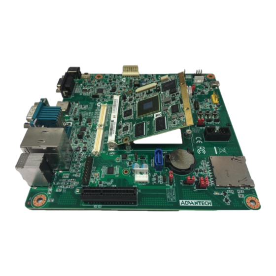
5. I/O Specification 5.1 ROM-7421 evaluation board overview CAN0 RJ45 HDMI Audio Jack COM2 USB 3.0 DC-in GPIO Copyright © 1983-2016 Advantech Co., Ltd. All Rights Reserved... -
Page 13: Connectors And Headers
BKLT1 SATA SATA PWR Battery Charger PCIE LVDS2 LVDS1 I2S to CODEC 5.2 Connectors and Headers A. DC Jack Connector Please apply 12V power adapter through this connector. Signal +12V Shield Copyright © 1983-2016 Advantech Co., Ltd. All Rights Reserved... - Page 14 CAN buses with 5V level. The connector being used is standard DB9 in male. Signal C. HDMI ROM-DB7501 HDMI follow HDMI 2.0 Spec, supported resolution is up to 1920x1080 Signal TMDS_LANE2+ TMDS_LANE2- TMDS_LANE1+ TMDS_LANE1- TMDS_LANE0+ TMDS_LANE0- TMDS_CLK+ TMDS_CLK- DDC CLK DDC DAT Copyright © 1983-2016 Advantech Co., Ltd. All Rights Reserved...
- Page 15 MDI2- MDI3+ MDI3- ACTIVE LED - ACTIVE LED + LINK 1000 - LINK 100 - USB PORT 2 - USB PORT 2 + USB PORT 1 - USB PORT 1 + Copyright © 1983-2016 Advantech Co., Ltd. All Rights Reserved...
- Page 16 SPI pin header Signal SPI0_CS0# SPI0_CLK SPI0_MOSI SPI0_MISO SPI0_CS1# I. I2C I2C Connector Signal I2C_DATA I2C_CLK J. I2S I2S to audio codec board (Referenced P/N: 9696MEG510E ) Signal AUDIO_VDDA AUDIO_VDDA I2S_SDIN Copyright © 1983-2016 Advantech Co., Ltd. All Rights Reserved...
- Page 17 I2S_SDOUT I2S_LRCK I2S_CLK AUDIO_MCK I2C_AUDIO_CLK MIC_BIAS I2C_AUDIO_DATA HP_R MIC_IN HP_L K. OTG USB OTG Port for ROM-DB7501 Signal USB_OTG D- USB_OTG D+ OTG ID L. COM1 4-wire RS-232 Signal Copyright © 1983-2016 Advantech Co., Ltd. All Rights Reserved...
- Page 18 LVDS CK- LVDS CK+ DID_CK DID_DAT LVDS D3- LVDS D3+ LVDS_CTRL N. BKLT 1&2 LVDS1 and LVDS2 Backlight Signal +VDD BKL_ENABLE Brightness O. USB USB Pin header for ROM-DB7501 Signal USB0_DN_X USB3_DN_X Copyright © 1983-2016 Advantech Co., Ltd. All Rights Reserved...
- Page 19 Smart Battery for ROM-DB7501 Signal BAT_THER BAT_ID_CN I2C_DAT_BAT I2C_CK_BAT +VBATT +VBATT Q. SATA SATA /SATA DOM support Signal SATA_TX+ SATA_TX- SATA_RX- SATA_RX+ SATA DOM Pin 7 R. SATA Power SATA/SATA DOM Power Signal +12V Copyright © 1983-2016 Advantech Co., Ltd. All Rights Reserved...
- Page 20 PCIE to mini-PCIe adapter card reference P/N is 9680015491 Signal Signal +12V +12V +12V +12V +12V +12V PCIE_A_CK PCIEX_A_JTAG2 PCIE_A_DAT PCIEX_A_JTAG3 PCIEX_A_JTAG4 PCIEX_A_JTAG5 PCIEX_A_JTAG1 PWRGD Mechanical Key Reserved PCIE_A_REFCK+ PCIE_A_X_TX+ PCIE_A_REFCK- PCIE_A_X_TX- PCIE_A_X_RX- PCIE_A_X_RX- Copyright © 1983-2016 Advantech Co., Ltd. All Rights Reserved...
-
Page 21: Test Scripts
Connect Pin 0 with Pin3 cd /sys/class/gpio; \ echo 0 > gpio0/value; grep "" gpio{0,3}/value; \ echo 1 > gpio0/value; grep "" gpio{0,3}/value; cd - • Connect Pin 1 with Pin 2 cd /sys/class/gpio; \ Copyright © 1983-2016 Advantech Co., Ltd. All Rights Reserved... - Page 22 # wifi_connect.sh "${SSID}" "${PSWD}" # DEV=wlan0 # SVC=$(P=`connmanctl services | grep "$SSID"` && echo -n wifi_${P#*wifi_}) # set - `connmanctl services $SVC | grep "Nameservers ="` # DNS=${4/,/} # ping -c5 $DNS -I $DEV Copyright © 1983-2016 Advantech Co., Ltd. All Rights Reserved...
- Page 23 # MAC=$(set - `ifconfig $DEV | grep HWaddr`; echo ${5~~} | sed "s/://g") # set - $(connmanctl services | grep $MAC) # SVC=$3 # set - `connmanctl services $SVC | grep "Nameservers ="` # DNS=${4/,/} # ping -c5 $DNS -I $DEV Copyright © 1983-2016 Advantech Co., Ltd. All Rights Reserved...
- Page 24 # ifconfig eth0 down; ifconfig eth1 down # pppd connect 'chat -v -s -t 10 "" "AT" "" "ATDT*99#" "CONNECT" ""' \ user username password password /dev/ttyUSB2 460800 nodetach crtscts \ debug usepeerdns defaultroute & # ifconfig Copyright © 1983-2016 Advantech Co., Ltd. All Rights Reserved...
- Page 25 # cat /etc/resolv.conf # ping -c5 8.8.8.8 Copyright © 1983-2016 Advantech Co., Ltd. All Rights Reserved...
Need help?
Do you have a question about the EmbCore ROM-7421 and is the answer not in the manual?
Questions and answers