EXFO RTU-2 User Manual
Hide thumbs
Also See for RTU-2:
- User manual (156 pages) ,
- Quick reference manual (2 pages) ,
- User manual (114 pages)
Table of Contents
Advertisement
Quick Links
Advertisement
Table of Contents

Related Manuals for EXFO RTU-2


Summary of Contents for EXFO RTU-2
- Page 1 User Guide RTU-2 www.EXFO.com...
- Page 2 EXFO Inc. (EXFO). Information provided by EXFO is believed to be accurate and reliable. However, no responsibility is assumed by EXFO for its use nor for any infringements of patents or other rights of third parties that may result from its use.
-
Page 3: Table Of Contents
Contents Contents Regulatory Information ......................v 1 Introducing the RTU-2 .................. 1 Main Features .........................1 LED Indicators Description ......................4 Product Registration .......................6 Technical Specifications ......................6 Conventions ..........................7 2 Safety Information ..................9 Other Safety Symbols on Your Unit ..................11 Laser Safety Information .......................12 Electrical Safety Information ....................13... - Page 4 Contents 6 Warranty ......................73 General Information ......................73 Gray Market and Gray Market Products ................74 Liability ..........................75 Exclusions ..........................75 Certification ..........................75 Service and Repairs .......................76 EXFO Service Centers Worldwide ..................77 Index .........................79 RTU-2...
-
Page 5: Regulatory Information
Electronic test and measurement equipment is exempt from FCC part 15, subpart B compliance in the United States of America and from ICES-003 compliance in Canada. However, EXFO Inc. makes reasonable efforts to ensure compliance to the applicable standards. The limits set by these standards are designed to provide reasonable protection against harmful interference when the equipment is operated in a commercial environment. -
Page 7: Introducing The Rtu-2
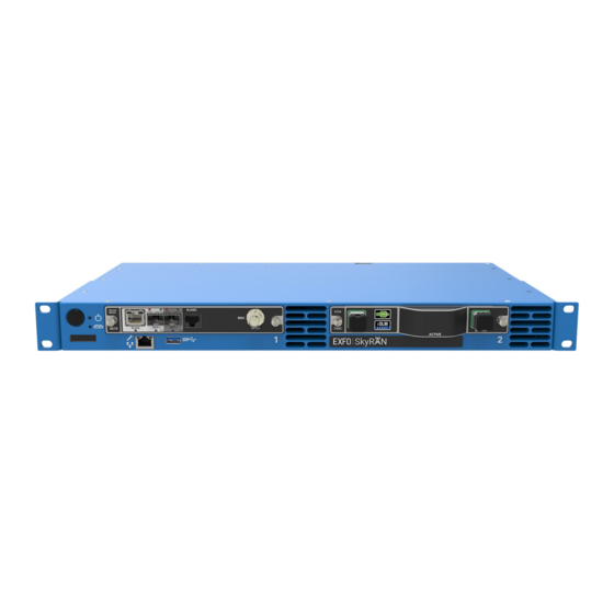
Introducing the RTU-2 The RTU-2 is a modular remote test unit that can be seamlessly integrated with Nova Fiber Monitoring System (FMS). FMS is the central management software for all EXFO's fiber monitoring probes such as the RTU-2, FG-750, and RTU-2 for point-to-point (P2P) and point-to-multipoint (P2MP) networks. - Page 8 Introducing the RTU-2 Main Features Front panel – RTU-2 On/Off button (see Turning on Your Unit on page 51 and Turning off Your Unit on page 52) LEDs Module slots USB 3.0 host port Ethernet (RJ-45) management port for local access...
- Page 9 Introducing the RTU-2 Main Features Back panel – RTU-2 Dry contact relays (reserved for future use) DC power inlet (dual feed) Main power switch Grounding lug USB 3.0 host ports Ethernet (RJ-45) management port Ethernet (RJ-45) port (for local access)
-
Page 10: Led Indicators Description
Introducing the RTU-2 LED Indicators Description Front view – Optional access panel DC power inlet (dual feed) USB 3.0 host ports Grounding lug Ethernet (RJ-45) port (for LAN/WAN connection) Note: You can also connect the unit to AC power with the AC/DC power adapter sold by EXFO. - Page 11 (see System Electrical Safety Information on page 13). If the problem persists, contact EXFO. Critical hardware error detected. The temperature of the room where the unit is located is critically too low or too high, or there could be a hardware malfunction.
-
Page 12: Product Registration
Introducing the RTU-2 Product Registration Product Registration You can now register your new EXFO products online and benefit from every possible opportunity to optimize their performance. By doing so, you will always be notified of the latest software updates, key product enhancements and up-to-date support information related to your products. -
Page 13: Conventions
Introducing the RTU-2 Conventions Conventions Before using the product described in this guide, you should understand the following conventions: ARNING Indicates a potentially hazardous situation which, if not avoided, could result in death or serious injury. Do not proceed unless you understand and meet the required conditions. -
Page 15: Safety Information
ARNING Use only accessories designed for your unit and approved by EXFO. For a complete list of accessories available for your unit, refer to its technical specifications or contact EXFO. - Page 16 Safety Information MPORTANT Refer to the documentation provided by the manufacturers of any accessories used with your EXFO product. It may contain environmental and/or operating conditions limiting their use. MPORTANT When you see the following symbol on your unit , make sure that you refer to the instructions provided in your user documentation.
-
Page 17: Other Safety Symbols On Your Unit
Direct current Alternating current The unit is equipped with an earth (ground) terminal. The unit is equipped with a protective conductor terminal. The unit is equipped with a frame or chassis terminal. On (Power) Off (Power) On/off (Power) Fuse RTU-2... -
Page 18: Laser Safety Information
Refer to the user documentation of the different modules for the relevant laser safety information. The modules and instruments that you use with your unit may have different laser classes. Refer to their user documentation for the exact information. RTU-2... -
Page 19: Electrical Safety Information
(AC or DC circuits). The power cord of the AC/DC power adapter can be considered the disconnect device to the main power. If you intend to connect your RTU-2 to AC power, use only the listed and certified AC/DC power adapter provided by EXFO with your unit. - Page 20 Unless otherwise specified, all interfaces are intended for connection to ES1 circuits only. Capacitors inside the unit may be charged even if the unit has been disconnected from its electrical supply. AUTION Position the unit so that the air can circulate freely around it. RTU-2...
- Page 21 Measured in 0 °C to 31 °C (32 °F to 87.8 °F) range, decreasing linearly to 50 % at 40 °C (104 °F). Not exceeding ± 10 % of the nominal voltage. Range: –38.5 - –70 V Taking into account the maximum possible power consumption of certain modules. The maximum current limit is lower when the optional access panel is used. RTU-2...
-
Page 22: Automatic Fan Speed Management
If the temperature keeps rising and reaches the limit, your unit will turn off to both protect itself and protect the modules it houses. AUTION Make sure to use protective covers over empty slots of your unit to avoid overheating. RTU-2... -
Page 23: Getting Started With Your Unit
The location is isolated from strong electromagnetic fields produced by electrical devices. The power cable and power supply are compatible with your power service. The power source is properly grounded and falls within the internal power supply rating. RTU-2... -
Page 24: Installing The Optional Access (Junction) Panel
ARNING For your safety and to avoid damaging your RTU-2 unit, always ensure that the disconnect devices to which the unit will be connected are turned off until you have completed all the installation procedures. - Page 25 2. Ensure that no USB or electrical cables are connected to the RTU-2. 3. Position the RTU-2 so that its top panel rests on a flat surface such as a table. 4. Install the mounting brackets as follows: 4a.
- Page 26 5. Attach the access panel as follows: 5a. Place the access panel (shown in gray below) on the RTU-2 so that the screw holes for the cover are visible. Ensure that the access panel is positioned in front of the mounting bracket legs.
- Page 27 6b. Connect the straight part of the Ethernet cable to the corresponding port located at the back of the access panel. 6c. Connect the angled part of the USB cables to one of the corresponding ports located at the back of the RTU-2. 1 2 3 4 RTU-2...
- Page 28 6d. Connect the angled part of the Ethernet cable to the LAN/WAN Ethernet port ( ) located at the back of the RTU-2. 7. Move the grounding lug as follows: 7a. Remove the two Phillips screws and the grounding lug from the back panel of the RTU-2.
- Page 29 You can discard this terminal block as you will no longer need it. Note: If no terminal block was attached to the RTU-2 at time of purchase, but one was provided separately in a bag, you can simply discard this terminal block as you will not need it.
- Page 30 9a. Position the power cable of the access panel so that its connector is aligned properly with the bay containing the electrical connectors of the RTU-2. 9b. Slide the connector all the way into the bay until it stops. 9c. Secure the connector in place with the two screws.
- Page 31 11. Secure the power cable with the 80 mm x 2.3 mm (#1001051) cable tie, as shown below. Once the power cable is secured, cut off the excess length of the cable tie. Otherwise, you will not be able to install the cover later. RTU-2...
- Page 32 12a.From the back of the access panel, slide the cover forward until it clips unto the cable retainer. 12b.Secure the cover in place with three M3 x 5 flat-head (#1067832) screws. The optional access panel is now installed properly and ready to use. RTU-2...
-
Page 33: Installing Your Unit And The Optional Front Access Panel In A Rack
Failure to provide adequate cooling clearance may result in an excessive internal temperature, thus reducing the reliability of your RTU-2 unit. Note: There is no need to leave an empty slot between units when you stack them one on top of the other inside a rack. - Page 34 To install your unit in a rack: 1. Ensure that your unit is turned off. AUTION You should remove all your modules from the RTU-2 unit before installing it into a rack. Otherwise, they could be damaged or their calibration could be affected.
- Page 35 3b. Align the holes of the first bracket with the holes of the unit’s casing at the position that best suits your installation needs. You can even invert position of the mounting bracket if necessary. Brackets in standard position Brackets in inverted position RTU-2...
- Page 36 To ground your unit properly, you must ensure that there is a metal-to-metal contact between the rack and the mounting hardware. For this reason, EXFO recommends to use thread-forming screws, star (tooth) lock washers, or similar hardware that remove any paint or non-conductive coatings.
-
Page 37: Grounding Your Unit
All wiring and installation must be in accordance with local building and electrical codes acceptable to the authorities in the countries where the equipment is installed and used. If you are not sure on how to proceed, consult a certified electrician. RTU-2... - Page 38 Back panel – RTU-2 Front view – Optional access panel 2. Prepare the ground wire (#14 AWG, green), and attach one of its ends to the unit’s or access panel’s grounding lug using a crimping tool.
-
Page 39: Connecting A Monitoring Device To The Dry Contact Relays
System relay: Activated when all the system components are working normally (the system LED is green). AUTION For optimum performance and safety, you must either crimp a terminal (ferrule) onto the stranded conductors, or tin them before installing them in the terminal block. RTU-2... - Page 40 2. When the terminal block is loose, gently pull it toward you to remove it, exposing the pins. 3. Crimp each wire with a terminal (ferrule) or tin each of them. 4. Unscrew the screws (shown in grey) located at the top of the terminal block. RTU-2...
- Page 41 System relay Pin 4 - NO = Normally open Pin 5 - C = Common Pin 6 - NC = Normally closed 6. Tighten the screws located at the top of the terminal block to secure the wires in place. RTU-2...
- Page 42 7. Ensure that the terminal block is aligned properly with the bay containing the pins. 8. Slide the terminal block all the way into the bay until it stops. 9. Screw the two screws to secure the terminal block in place. The dry contact relays are now installed properly. RTU-2...
-
Page 43: Inserting And Removing Test Modules
Getting Started with Your Unit Inserting and Removing Test Modules Inserting and Removing Test Modules AUTION Never insert or remove a module while the RTU-2 unit is turned on. This will result in immediate and irreparable damage to both the module and unit. - Page 44 6. Turn on the unit by pressing the on/off button. The module will be detected automatically during the startup sequence. 7. Using the Nova Fiber Web application, from the Status window, confirm that the detection of the module is completed. 8. Connect the optical fibers as needed. RTU-2...
- Page 45 Getting Started with Your Unit Inserting and Removing Test Modules 9. From FMS, proceed as follows. 9a. If the RTU-2 unit was already attached before you inserted a module, detach it. 9b. Attach the RTU-2 unit hosting the newly inserted module.
- Page 46 6. Turn on the unit by pressing the on/off button. 7. Using the Nova Fiber Web application, from the Status window, confirm that the removal of the module is completed. 8. Reconnect the optical fibers as needed. RTU-2...
-
Page 47: Connecting Rtue-9110/Rtue-9120 External Switches To Your Unit
Connecting RTUe-9110/RTUe-9120 External Switches to Your Unit 9. From FMS, proceed as follows. 9a. If the RTU-2 unit was already attached before you removed a module, detach it. 9b. Attach the RTU-2 unit from which you have just removed a module. - Page 48 2. Connect the other end of the USB cable to one of the USB ports located on the back panel of the unit or on the front of the optional access panel. Back panel – RTU-2 USB cable Front view – Optional access panel...
-
Page 49: Connecting Your Unit To A Power Source
To avoid fire hazards and ensure your safety, when you intend to connect your unit to DC power, always select a wire gauge according to the RTU-2 unit’s ratings, cable length, and local electrical code. AUTION For optimum performance and safety, you must either crimp a ... - Page 50 2. Ensure all power is off or disconnected at the source. Note: A certified over-current protection of 10 A must be installed at the power secondary distribution. 3. Ensure that the unit is grounded properly. For more information, see Grounding Your Unit on page 31. RTU-2...
- Page 51 Connecting Your Unit to a Power Source 4. From the back panel of your unit or the front of the optional access panel, unscrew the two screws holding the terminal block in place. Back panel – RTU-2 Screws Front view – Optional access panel Screws 5.
- Page 52 7. Pair the power leads with the appropriate power terminal for each of the feed, respecting the polarity as indicated just above the terminal block (unit) or on the terminal block (optional access panel). First feed Second feed RTU-2...
- Page 53 13. If you are not using the optional access panel, flip the unit’s main power switch to the on position. Main power switch You are now ready to turn on the unit (see Turning on Your Unit on page 51). RTU-2...
- Page 54 Back panel Main power switch in off position 2. Ensure all power is off or disconnected at the source. 3. Ensure that the unit is grounded properly. For more information, see Grounding Your Unit on page 31. RTU-2...
- Page 55 4. If necessary, remove the block terminal as follows: 4a. From the back panel of your unit or the front of the optional access panel, unscrew the two screws holding the terminal block in place. Back panel – RTU-2 Screws Front view – Optional access panel Screws 4b.
- Page 56 10. If you are not using the optional access panel, flip the unit’s main power switch to the on position. Main power switch You are now ready to turn on the unit (see Turning on Your Unit on page 51). RTU-2...
-
Page 57: Turning On Your Unit
Getting Started with Your Unit Turning on Your Unit Turning on Your Unit Before you turn on the unit for the very first time, EXFO recommends that you read the safety and installation instructions. To turn on the unit: 1. If it is not already done, connect your unit to an AC or a DC power source (see the corresponding section for safety information and detailed instructions). -
Page 58: Turning Off Your Unit
To avoid damaging your unit when you need to disconnect it from its external power source, first turn the unit off. Then, turn off the disconnect devices to which the unit is connected before proceeding. To turn off the unit completely from the unit itself: Press the on/off button. RTU-2... -
Page 59: Working With Your Unit For The First Time
Working With Your Unit for the First Time Working With Your Unit for the First Time By starting to use your unit, you implicitly agree to the EXFO and third-party EULAs related to your unit and instruments. You will need a computer (laptop) and a network cable to connect to your RTU-2 unit. - Page 60 Getting Started with Your Unit Working With Your Unit for the First Time 6. From the Status page, ensure that the test modules have been detected as expected. 7. Configure the network as follows: 7a. From the list, select Network. RTU-2...
- Page 61 Getting Started with Your Unit Working With Your Unit for the First Time 7b. Set the IP address and various parameters as needed, and then click Apply to confirm. To confirm the changes RTU-2...
- Page 62 You can set the date and time manually or use an NTP server. Click Apply to confirm. To confirm the changes Note: After a successful connection between FMS and your unit, FMS will provide its own NTP server. RTU-2...
- Page 63 9b. Click Add to add a trusted certificate to the list. The certificate file that you provide must be in PEM format. Identifies your RTU-2 unit so that it can be seen as “trusted” by FMS. To delete a specific trusted certificate...
- Page 64 Getting Started with Your Unit Working With Your Unit for the First Time 10. Connect your unit to FMS as follows: 10a.From the list, select Operating mode. 10b.In the Nova Fiber FMS box, enter the name of your FMS server (ex.: abc.fms.your_company.com). RTU-2...
- Page 65 10c. If your system is configured so that FMS requires the authentication of all RTU-2 units, click Request device certificate. If FMS does not require the authentication of the RTU-2 units, go directly to step 10e. 10d.When the application prompts you, enter the username and password for certificate retrieval that was provided by your system administrator.
- Page 66 “Not configured” to “Connecting” to “Established”. If any connection problem occurs, the application will display “Connecting” along with the last error, and the RTU-2 will periodically try to reconnect to the FMS server. Note: If you need to detach your unit from the link, you can click Disconnect. At this point, since there are no monitoring data acquired so far, no data can be lost.
- Page 67 11. If you need to define a login banner, you can do so as follows: 11a.From the list, select Administration. 11b.Select the Enable banner check box. 11c. Enter the desired text, and then click Apply to confirm. Your RTU-2 unit is now configured properly. RTU-2...
-
Page 69: Maintenance
ARNING The use of controls, adjustments and procedures, namely for operation and maintenance, other than those specified herein may result in hazardous radiation exposure or impair the protection provided by this unit. RTU-2... -
Page 70: Replacing Fuses
(or the access panel). 3. Gently pull on the fuse carrier to remove it. 4. Repeat with the second fuse carrier. 5. Check and replace the fuses, if necessary. RTU-2... - Page 71 10. Repeat with the second fuse carrier. 11. Connect the unit to the power source (either from the unit itself or the access panel) and turn on the unit. RTU-2...
-
Page 72: Recalibrating Your Modules
Maintenance Recalibrating Your Modules Recalibrating Your Modules When they are used exclusively in a system based on the RTU-2, the FTBx-730C OTDR modules have a recommended calibration interval of three years. This value takes precedence over the recommended interval specified in their respective user guides. -
Page 73: Troubleshooting
Troubleshooting Solving Common Problems Before calling EXFO’s technical support, you may want to consider the following solutions to problems that could occur. Problem Possible Cause Solution My unit does not start. There is a problem related If your unit is connected ... - Page 74 The switch has not been Disconnect, then reconnect external switch that I have detected. the switch. just connected is not Ensure that the RTU-2 unit is working. on and that its System LED ) is green and not blinking. The unit does not recognize Defective module.
-
Page 75: Retrieving Logs
Retrieving Logs There are two types of logs that you can retrieve from the Nova Fiber Web application: The audit log that lists events and changes that occurred on the RTU-2 unit. The system log that provides special information that you can send to ... - Page 76 The Debug level should be used temporarily as it can slow down the system. EXFO recommends to set the level back to Warning once the debug operation is complete.
-
Page 77: Contacting The Technical Support Group
Contacting the Technical Support Group To obtain after-sales service or technical support for this product, contact EXFO at one of the following numbers. The Technical Support Group is available to take your calls from Monday to Friday, 8:00 a.m. to 7:00 p.m. -
Page 78: Transportation
Pack the unit in its original packing material when shipping. Avoid high humidity or large temperature fluctuations. Keep the unit out of direct sunlight. Avoid unnecessary shocks and vibrations. RTU-2... -
Page 79: Warranty
Warranty General Information EXFO Inc. (EXFO) warrants this equipment against defects in material and workmanship for a period of two years from the date of original shipment. EXFO also warrants that this equipment will meet applicable specifications under normal use. -
Page 80: Gray Market And Gray Market Products
(hereafter unauthorized intermediary). EXFO considers that a product originates from the gray market (hereafter gray market product) in the following situations: A product is sold by an unauthorized intermediary. -
Page 81: Liability
Liability Liability EXFO shall not be liable for damages resulting from the use of the product, nor shall be responsible for any failure in the performance of other items to which the product is connected or the operation of any system of which the product may be a part. -
Page 82: Service And Repairs
5. Return the equipment, prepaid, to the address given to you by support personnel. Be sure to write the RMA number on the shipping slip. EXFO will refuse and return any package that does not bear an RMA number. -
Page 83: Exfo Service Centers Worldwide
Fax: +86 (755) 2955 3101 Xintian Avenue, support.asia@exfo.com Fuhai, Bao’An District, Shenzhen, China, 518103 To view EXFO's network of partner-operated Certified Service Centers nearest you, please consult EXFO's corporate website for the complete list of service partners: http://www.exfo.com/support/services/instrument-services/ exfo-service-centers. RTU-2... -
Page 85: Index
AC power ......43, 48 unit to DC power ......43, 44 identification label........71 conventions, safety ........7 indoor use ........... 14 covers, unit..........14 input current ..........15 current, electrical ........15 customer service.......... 76 RTU-2... - Page 86 ....... 17 general information....... 63 return merchandise authorization (RMA) ..76 port ............. 3, 4 RJ-45 port..........3, 4 maximum input current ......15 RTU-2, installing .......... 28 module insertion ..........37 removal ..........37 mounting brackets ........27 safety caution ............
- Page 87 14, 17, 28 repairing ..........14 ventilation ..........14 USB ports ..........2, 3, 4 ventilation ........... 14 warranty certification ........... 75 exclusions ..........75 general ..........73 liability ........... 75 null and void.......... 73 wizard, configuration........53 yellow LED............. 4 RTU-2...
- Page 90 · info@EXFO.com CORPORATE HEADQUARTERS 400 Godin Avenue Quebec (Quebec) G1M 2K2 CANADA Tel.: 1 418 683-0211 · Fax: 1 418 683-2170 TOLL-FREE (USA and Canada) 1 800 663-3936 © 2021 EXFO Inc. All rights reserved. Printed in Canada (2021-04) ...
Need help?
Do you have a question about the RTU-2 and is the answer not in the manual?
Questions and answers