EXFO RTU-2 Quick Reference Manual
Skyran platform
Hide thumbs
Also See for RTU-2:
- User manual (156 pages) ,
- User manual (90 pages) ,
- User manual (114 pages)
Advertisement
Table of Contents
Removing Modules
1
From ToolBox X, click the
button.
C
AUTION
Once you have pressed the
button, wait until the status of the
module switches to "Safe to Remove" in ToolBox X.
Note: The
button is not available for the RTUe-9110 external switches because they do not
support ejection. If you need to remove such a switch from the system, ensure that no test is
underway, and then simply disconnect the optical fibers and the USB cable.
2
Turn the two retaining screws counterclockwise until they are loose (do not remove them completely).
3
Hold the module by its sides or by the retaining screws (NOT by the connectors) and pull it out.
Retaining screws
(can be used as handles to
safely pull the module out)
Connecting to Your Unit
Connect a network cable between the front or rear management port of the unit (
1
Ethernet port of a computer (laptop) on which AMT Remote Access is installed
(http://www.exfo.com/software/exfo-apps > PC Software).
From AMT Remote Access, enter the connection information:
2
The default static IP address is: 192.168.200.1. The IP address
is also visible from the built-in display on the front of the unit.
The default user name is: admin.
The default password is: !Exfo123.
Note: You may have to modify the IP address of the computer so that
the computer and unit can "see" each other. Both IP addresses
must be within the same range of addresses
(ex.: 192.168.200.20).
Note: If several units are connected to the same network with the default static IP address, you may
have to modify the IP addresses of these units to avoid connection problems (not accessing
the right unit). You can use their host names to connect to these units, and then change their IP
addresses.
Understanding the Instrument Statuses
Ready
The module or external switch is available for tests.
In use
The module or external switch is currently in use.
Ejecting
The module is being prepared for safe removal from the unit.
Safe to remove
The module can now be safely removed from the unit.
Error
The module or external switch cannot be used at this time because it had to protect itself from a critical problem.
© 2018 EXFO Inc. All rights reserved.
Printed in Canada (2018-02)
P/N: 1072223
Version: 1.0.0.1
Quick Reference Guide
) and an
Accessing Connectors and Ports
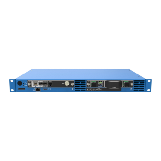
Front panel
On/Off button
LEDs
Click to have access to
Windows, the unit and the
applications.
USB 3.0 host port
Ethernet (RJ-45) management port for local access
(to connect a portable computer to the unit)
Built-in display
(for network /system information)
Back panel
DC power inlet (–48 V, dual feed)
Main power switch
For more information,
refer to the user guide.
RTU-2
SkyRAN Platform
Module slots
Dry contact relays
(reserved for future use)
Grounding lug
USB 3.0 host ports
Ethernet (RJ-45) port
Ethernet (RJ-45) management port
(for LAN/WAN connection)
(for local access)
Advertisement
Table of Contents

Related Manuals for EXFO RTU-2


Summary of Contents for EXFO RTU-2
- Page 1 The module or external switch cannot be used at this time because it had to protect itself from a critical problem. (for LAN/WAN connection) (for local access) © 2018 EXFO Inc. All rights reserved. Printed in Canada (2018-02) For more information, P/N: 1072223 Version: 1.0.0.1...
- Page 2 Once it is done, install the prepared Ensure that you read and understand all the warnings and wires respecting the polarity. installation information provided in the RTU-2 user guide before proceeding. Connect the provided AC/DC power Place the module horizontally so that the connector pins are at the back, and the protruding edges are adapter.
Need help?
Do you have a question about the RTU-2 and is the answer not in the manual?
Questions and answers