
Subscribe to Our Youtube Channel
Related Manuals for WEG SCW100 Series


Summary of Contents for WEG SCW100 Series
- Page 1 Motors | Automation | Energy | Transmission & Distribution | Coatings Starter Manager SCW100 User's Manual...
- Page 2 User Manual Series: SCW100 Language: English Document: 10006801366 / 01 Model: Modbus-RTU Firmware version: V1.0X Publication Date: 08/2021...
- Page 3 Summary of the Revisions The information below describes the revisions made to this manual. Version Revision Description V1.0X First edition V1.0X General review...
-
Page 4: Table Of Contents
Summary 1 SAFETY INSTRUCTIONS ............... 1-1 1.1 SAFETY WARNINGS IN THIS MANUAL ..................1-1 1.2 PRELIMINARY RECOMMENDATIONS ..................1-1 2 GENERAL INFORMATION ..............2-1 2.1 ABOUT THE MANUAL ........................2-1 2.2 TERMS AND DEFINITIONS USED IN THE MANUAL ..............2-1 2.3 NUMERICAL REPRESENTATION ....................2-2 2.4 ABOUT THE SCW100 ........................ - Page 5 Quick Parameter Reference QUICK PARAMETER REFERENCE Modbus Factory User Parameter/ Description Adjustable Range Properties Page Setting Setting Address Firmware Version 0.0 to 655.35 ro, 16 bit Rotating Switch S1 0 to 15 ro, 8 bit Rotating Switch S2 0 to 15 ro, 8 bit Rotating Switch S3 0 to 15...
- Page 6 Quick Parameter Reference Modbus Factory User Parameter/ Description Adjustable Range Properties Page Setting Setting Address Reset P1 C1 Operation Counter 0 to 65535 rw, 16 bit Reset P1 C2 Operation Counter 0 to 65535 rw, 16 bit Reset P2 C1 Operation Counter 0 to 65535 rw, 16 bit Reset P2 C2 Operation Counter...
- Page 7 Quick Parameter Reference Modbus Factory User Parameter/ Description Adjustable Range Properties Page Setting Setting Address P4 - Last Alarm 2 0 to 65535 ro, 16 bit 5-10 P4 - Last Alarm 3 0 to 65535 ro, 16 bit 5-10 P4 - Last Alarm 4 0 to 65535 ro, 16 bit 5-11...
-
Page 8: Safety Instructions
Safety Instructions 1 SAFETY INSTRUCTIONS This manual contains the information necessary for the correct use of the SCW100 Starter Manager. It was developed to be used by people with proper technical training or qualification to operate this kind of equipment. 1.1 SAFETY WARNINGS IN THIS MANUAL The following safety warnings are used in this manual: DANGER! -
Page 9: General Information
General Information 2 GENERAL INFORMATION 2.1 ABOUT THE MANUAL This manual contains directions to install and commission WEG SCW100 Starter Manager and describes its main features. For information on other functions, accessories and operating conditions, refer to the following manual: Modbus-RTU communication manual. -
Page 10: Numerical Representation
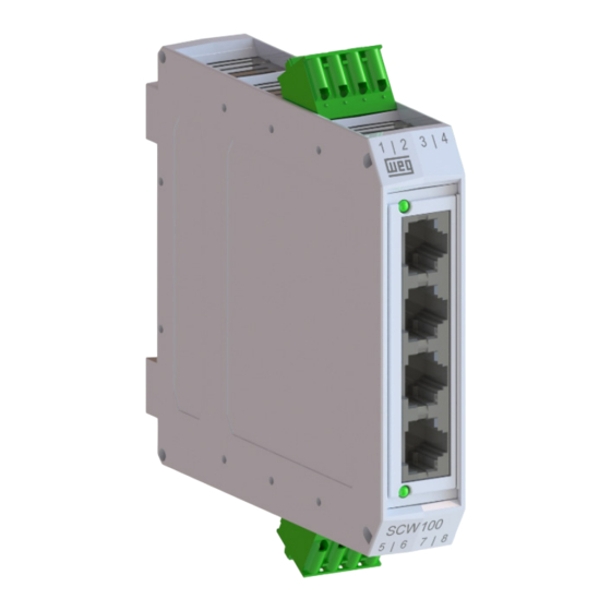
'h' after the number. 2.4 ABOUT THE SCW100 The SCW100 (Smart Connection WEG) is a motor starter manager with a line of accessories developed to ensure the drive and complete management of electric motor starters. It has an isolated fieldbus communication network, RS485 with Modbus-RTU protocol, which allows connection to a PLC (edge device) that can send commands and read diagnostics, processing and providing information for a higher level network. - Page 11 General Information (a) Starter manager (SCW100-SM) (b) Forward start contactor module (SCW100-CM-001) (c) Reverse start contactor module (SCW100-CM-002) (d) Forward starter module (SCW100-CM-011) (e) Reverse starter module (SCW100-CM-012) (f) Input and output devices (I/O) Figure 2.1: SCW100 components SCW100 | 2-3...
-
Page 12: How To Specify The Scw100 Model
General Information 2.5 HOW TO SPECIFY THE SCW100 MODEL To specify the SCW100 model, see the catalog available for download on the website: www.weg.net. 2.6 RECEIVING AND STORING The SCW100 is supplied packaged in a cardboard box. This package contains a label outside describing the main characteristics of the product: model, WEG stock item, serial number, manufacturing date and firmware version. -
Page 13: Installing And Connecting
CWB9…18/CWB25..38 line and MPW40 motor-protective circuit breaker. For details on mounting, refer to the installation guide that accompanies the product (SCW100-CM). This installation guide is also available for download on the website: www.weg.net. Figure 3.1: Mounting the Starter Manager (SCW100-SM) on DIN rail 35 mm (1.32 in) -
Page 14: Electrical Installation
Installing and Connecting 3.2 ELECTRICAL INSTALLATION DANGER! The following information is a guide for proper installation. Comply with applicable regulations for electrical installations. The Starter Manager (SCW-100-SM), shown in Figure 3.2 on page 3-2, is supplied with two removable terminal blocks: one for the power cable connections (connector 5) and another for the RS485 communication interface (connector 6) - both with 4 pins each. - Page 15 Installing and Connecting SCW100-CM-001 SCW100-CM-002 SCW100-SM SCW100-CM-011 SCW100-CM-012 Figure 3.3: Connections of the SCW100-SM to the Starter Modules (SCW100-CM) SCW100 | 3-3...
-
Page 16: Energization
Installing and Connecting 3.3 ENERGIZATION The Starter Manager (SCW100-SM) is powered through connector 5 Figure 3.2 on page 3-2, as indicated in Table 3.1 on page 3-4. Table 3.1: Power supply connector terminals Lettering Description 24 Vdc - Control system power supply A1 (AUX) 24 Vdc - Digital output power supply 0 Vdc - Power supply reference... -
Page 17: Connecting The Starter Modules Or I/O Devices
A (-) Terminal A (Line -) Reference 0 V NOTE! For the settings of the RS485 network, refer to the communication manual. This manual is available for download on WEG website: www.weg.net. Shield Shield A (-) A (-) B (+) - Page 18 Pin 6 (SHIELD) of the RS485 interface connector must be connected to a protective earth. NOTE! For further details regarding the settings of the Starter Manager (SCW100) to operate on a network, refer to the SCW100 communication manuals, available for download on the website: www.weg.net. 3-6 | SCW100...
-
Page 19: Operating Modes
Operating Modes 4 OPERATING MODES The SCW100 has two operating modes: Starter and Transparent. It is programmed at the factory to the "Starter" mode, which simplifies the control, monitoring and diagnostics on the components of a forward and reverse starter. In this operating mode, the SCW100 performs the complete management of motor starters, reporting errors, alarms, times, diagnostics, etc. -
Page 20: Modbus Address/Parameter Description
If the configuration of switch S1, S2 or S3 is changed, it will only be valid after the SCW100 is turned off and back on. NOTE! For further details regarding the settings of the Starter Manager (SCW100) to operate on a network, refer to the SCW100 communication manuals, available for download on the website: www.weg.net. SCW100 | 5-1... -
Page 21: Status Of The Digital Inputs
Description of the Modbus Parameters/Addresses 5.3 STATUS OF THE DIGITAL INPUTS It shows the status of each of the twelve digital inputs, in decimal. It must be converted to binary for a clearer interpretation of the value read. The least significant bit represents DI1. Modbus address: 015. -
Page 22: Rs485 - Address
Description of the Modbus Parameters/Addresses 5.5 RS485 - ADDRESS Modbus address: 020. 020 – RS485 - Address Adjustable 0 to 255 Factory Setting: - Range: Properties: ro, 8 bit 5.6 RS485 - BAUD RATE Modbus address: 021. 021 – RS485 - Baud Rate Adjustable 0 = 9600 kbps Factory Setting: -... -
Page 23: Rs485 - Action For Communication Fault
NOTE! To set these parameters, see the SCW100 communication manuals, available for download on the website: www.weg.net. 5.10 CONTACTOR CLOSING AND OPENING TIME It informs the closing and opening time in ms (milliseconds) of each contactor, for each starter (only in the starter... -
Page 24: Operation Counters
Description of the Modbus Parameters/Addresses 135 – P4 - Contactor 2 Opening Time Adjustable 0 to 65535 ms Factory Setting: - Range: Properties: ro, 16 bit Where Px represents the starter number, associated with the respective RJ45 connector, as shown in Figure 3.2 on page 3-2. -
Page 25: Saving Operation Counters In Mem Nv
Description of the Modbus Parameters/Addresses 5.12 SAVING OPERATION COUNTERS IN MEM NV This command is used if you want to save the operation counters immediately in non-volatile memory. Just write a non-zero value at this address to force the immediate recording of the operation counters. Return to the zero value (false) after performing the recording procedure. -
Page 26: Status Of The Starters
Description of the Modbus Parameters/Addresses 5.14 STATUS OF THE STARTERS The following addresses show the following status of each starter: Start Ok, Stop Ok, Error, Alarm, Contactor. Modbus addresses 200, 204, 208 and 212 indicate the starter status: 200 – P1 Status 204 –... - Page 27 Description of the Modbus Parameters/Addresses 210 – P3 Status - Error 214 – Status P4 - Error Adjustable 0 to 65535 Factory Setting: - Range: Properties: ro, 16 bit Stuck contact (error = 1), it is reported when the contacts are already closed when the contactor is turned on, or when the contacts remain closed when the contactor is turned off.
-
Page 28: Error And Alarm Log
Description of the Modbus Parameters/Addresses 5.15 ERROR AND ALARM LOG The SCW100 reports up to five errors and alarms for each starter. Errors are automatically saved every 10 minutes, so you can lose some errors that haven't been saved yet in case the product is turned off. The errors and alarms are presented in the circular buffer system, that is, the most recent events replace the oldest ones, which are discarded. - Page 29 Description of the Modbus Parameters/Addresses 319 – P4 - Last Error 5 Adjustable 0 to 65535 Factory Setting: - Range: Properties: ro, 16 bit Where Px represents the starter number, associated with the respective RJ45 connector, as shown in Figure 3.2 on page 3-2.
-
Page 30: Operating Modes
Description of the Modbus Parameters/Addresses 338 – P4 - Last Alarm 4 339 – P4 - Last Alarm 5 Adjustable 0 to 65535 Factory Setting: - Range: Propriedades: ro, 16 bit Where Px represents the starter number, associated with the respective RJ45 connector, as shown in Figure 3.2 on page 3-2. -
Page 31: Cpu Temperature
Description of the Modbus Parameters/Addresses 406 – P3 - Timeout Contactor 407 – P4 - Timeout Contactor Adjustable 20 to 5000 ms Factory Setting: 500 ms Range: Properties: rw, 16 bit Where Px represents the starter number, associated with the respective RJ45 connector, as shown in Figure 3.2 on page 3-2. -
Page 32: Forward Start Command
Description of the Modbus Parameters/Addresses 5.20 FORWARD START COMMAND In "starter" mode, this is the command that turns on each of the four starters in the forward direction, that is, it activates contactor 1 of the respective RJ45 port. Each of the four least significant bits represents a starter, which can be driven individually or combined. -
Page 33: Stop Command
Description of the Modbus Parameters/Addresses 5.22 STOP COMMAND In the "starter" mode, this is the command responsible for turning off each of the four starters. Each of the four least significant bits represents a starter, which can be driven individually or combined. Where: P1, P2, P3 and P4: starters 1, 2, 3 and 4, respectively. -
Page 34: Diagnostics Via Leds
Diagnostics Via LED 6 DIAGNOSTICS VIA LEDS The Starter Manager (SCW100-SM) has two LEDs to indicate if the device is energized and the status of the RS485 communication. Power LED RS485 LED Figure 6.1: Indication LEDs Table 6.1: Starter Manager Status (SCW100-SM) via LEDs Indication Description Green... -
Page 35: Technical Characteristics
Technical Characteristics 7 TECHNICAL CHARACTERISTICS Mounting position „ Pollution degree (IEC 61131-2) „ Protection rating (IEC 60529) Starter Manager (SM): IP20 „ General Data Starter Modules (CM): IP20 „ Allowed ambient temperature Operation: 0... +55 (+32... +131 ºF) „ Storage and transportation: -25...+ 80 ºC (-13... +176 ºF) „... -
Page 36: Mechanical Data
Technical Characteristics 7.1 MECHANICAL DATA 22,5 [0.89] 110 [4.33] Figure 7.1: Starter Manager (SM) dimensions in mm [in] 72,3 [2.85] 44,8 [1.76] 53,9 [2.12] Figure 7.2: Dimensions of the Forward Starter Connection Module (CM-001) in mm [in] 72,3 [2.85] 89,6 [3.53] 53,9 [2.12] Figure 7.3: Dimensions of the Reverse Starter Connection Module (CM-001) in mm [in] 7-2 | SCW100... - Page 37 Technical Characteristics 63,0 [2.48] 44,7 [1.76] 39,5 [1.55] 44,8 [1.76] 53,9 [2.12] 72,3 [2.85] Figure 7.4: Dimensions of the Forward Starter with Motor-Protective Circuit Breaker Connection Module (CM-001) in mm [in] SCW100 | 7-3...
- Page 38 Technical Characteristics 63,0 [2.48] 44,7 [1.76] 39,5 [1.55] 89,6 [3.53] 53,9 [2.12] 72,3 [2.85] Figure 7.5: Dimensions of the Reverse Starter with Motor-Protective Circuit Breaker Connection Module (CM-001) in mm [in] 7-4 | SCW100...
Need help?
Do you have a question about the SCW100 Series and is the answer not in the manual?
Questions and answers