
Subscribe to Our Youtube Channel
Related Manuals for WEG SCW100 Series


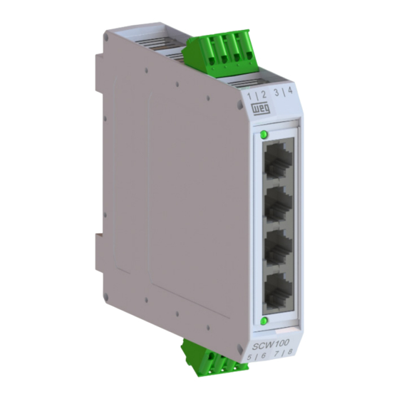
Summary of Contents for WEG SCW100 Series
- Page 1 Motors | Automation | Energy | Transmission & Distribution | Coatings CANopen SCW100 User’s Guide...
- Page 2 CANopen User’s Guide Series: SCW100 Language: English Document: 10008601670 / 01 Build 221 Publication Date: 04/2022...
- Page 3 Summary of Revisions The information below describes the reviews made in this manual. Version Revision Description Cancelled First edition...
-
Page 4: Table Of Contents
Contents CONTENTS ABOUT THE MANUAL ..................ABBREVIATIONS AND DEFINITIONS . - Page 5 Contents 8.3.1 PDO Mapping Objects ................23 8.3.2 Receive PDOs .
-
Page 6: About The Manual
ABOUT THE MANUAL ABOUT THE MANUAL This manual supplies the necessary information for the operation of the SCW100 starter manager using the CANopen protocol. This manual must be used together with the SCW100 user’s manual . ABBREVIATIONS AND DEFINITIONS ASCII American Standard Code for Information Interchange Controller Area Network CAN in Automation... -
Page 7: Main Characteristics
MAIN CHARACTERISTICS 1 MAIN CHARACTERISTICS Below are the main characteristics for communication of the starter manager SCW100 with CANopen accessory. Network management task (NMT). 5 transmission PDOs. 2 reception PDOs. Heartbeat Consumer. Heartbeat Producer. Node Guarding. SDO Client. SYNC producer/consumer. It is supplied with an EDS file for the network master configuration. -
Page 8: Interface Description
INTERFACE DESCRIPTION 2 INTERFACE DESCRIPTION 2.1 CHARACTERISTICS OF THE CAN INTERFACE Interface galvanically insulated and with differential signal, providing more robustness against electromagnetic interference. External power supply of 24 V. It allows the device to operate as CANopen slave. Allows data communication for equipment operation and parameterization. Enables communication using baud rates from 20 Kbits/s up to 1 Mbit/s. -
Page 9: Baud Rate
INTERFACE DESCRIPTION Valid addresses: 1 to 127 (01h to 7Fh); ✓ NOTE! For the changes in this setting be effective, the equipment must be powered off and on again. The address selected using the keys represents a hexadecimal value. Therefore, it must be converted to decimal, when necessary, in the parameterization of the CANopen master. -
Page 10: Terminating Resistor
INTERFACE DESCRIPTION 2.5 TERMINATING RESISTOR The product has a switch (S4) that can be activated to enable the termination resistor according to figure 2.1. The configurations of the switch to enable the termination resistor are shown in table 2.3. Table 2.3: Configurations of the switch (S4) that enables the termination resistor Switch Setting Option SW.1 = OFF and SW.2 = OFF... -
Page 11: Canopen Network Installation
CANOPEN NETWORK INSTALLATION 3 CANOPEN NETWORK INSTALLATION The CANopen network, such as several industrial communication networks, for being many times applied in aggressive environments with high exposure to electromagnetic interference, requires that certain precautions be taken in order to guarantee a low communication error rate during its operation. Recommendations to perform the connection of the product in this network are presented next. -
Page 12: Connection To The Network
CANOPEN NETWORK INSTALLATION Table 3.2: CANopen cable characteristics Cable Length (m) Resistence per Meter (mΩ/m) Conductor Cross Section (mm 0 ... 40 0.25 ... 0.34 40 ... 300 <60 0.34 ... 0.60 300 ... 600 <40 0.50 ... 0.60 600 ... 1000 <26 0.75 ... -
Page 13: Status
S STATUS 4 S STATUS Allows accessing starter manager SCW100 reading variables. S4 COMMUNICATION Read parameters that display information about the communication interfaces for the product. S4 Communication P0030: CAN - Address Range: 1 ... 127 Default: 1 Description: It allows viewing the address configured for CAN communication, programmed using DIP switches S1 and S2. S4 Communication P0031: CAN - Baudrate Range:... - Page 14 S STATUS S4 Communication P0035: CAN - TX CAN Telegrams Range: 0 ... 65535 Default: 0 Description: This parameter works as a cyclic counter that is incremented every time a CAN telegram is transmitted. It informs the operator if the device is being able to communicate with the network. S4 Communication P0036: CAN - Bus Off counter Range:...
-
Page 15: Configuration
C CONFIGURATION 5 C CONFIGURATION Allows accessing starter manager SCW100 writing variables. C2 COMMUNICATION Write parameters that allow configure the communication interfaces for the product. C2 Communication P0101: Action for Communication Fault Range: 0 ... 1 Default: 1 Description: It allows configuring the protection tripping mode for communication error. Indication Description 0 = No Action... -
Page 16: Operation In The Canopen Network
OPERATION IN THE CANOPEN NETWORK 6 OPERATION IN THE CANOPEN NETWORK 6.1 ACCESS TO THE DATA Each slave of the CANopen network has a list called object dictionary that contains all the data accessible via network. Each object of this list is identified with an index, which is used during the equipment configuration as well as during message exchanges. -
Page 17: Cob-Id
This file is used by a master or configuration software to program devices present at CANopen network. The EDS file is available from WEG website (http://www.weg.net). It is important to note if the EDS configuration file is compatible with the firmware version of the SCW100 starter manager. -
Page 18: Object Dictionary
OBJECT DICTIONARY 7 OBJECT DICTIONARY The object dictionary is a list containing several equipment data which can be accessed via CANopen network. An object of this list is identified by means of a 16-bit index, and it is based in that list that all the data exchange between devices is performed. -
Page 19: Manufacturer Specific Objects
OBJECT DICTIONARY Table 7.2: Lista de objetos – Communication Profile Índice Objeto Nome Tipo Acesso 1000h device type UNSIGNED32 1001h error register UNSIGNED8 1005h COB-ID SYNC UNSIGNED32 100Ch guard time UNSIGNED16 100Dh life time factor UNSIGNED8 1016h ARRAY consume heartbeat time UNSIGNED32 1017h producer heartbeat time... -
Page 20: Communication Objects Description
COMMUNICATION OBJECTS DESCRIPTION 8 COMMUNICATION OBJECTS DESCRIPTION This item describes in detail each of the communication objects available for the SCW100 starter manager. It is necessary to know how to operate these objects to be able to use the available functions for the SCW100 starter manager communication. -
Page 21: Object 1018H - Identity Object
COMMUNICATION OBJECTS DESCRIPTION 8.1.3 Object 1018h - Identity Object It brings general information about the device. Table 8.4: Object 1018h - Identity Object Index Sub- Name Type Access Value index Mapping Number of the last sub-index UNSIGNED8 Vendor ID UNSIGNED32 0000.0123h 1018h Product code... -
Page 22: Sdos Operation
COMMUNICATION OBJECTS DESCRIPTION 8.2.2 SDOs Operation A telegram sent by an SDO has an 8 byte size, with the following structure: Identifier 8 data bytes Command Index Subindex Object data 11 bits byte 0 byte 1 byte 2 byte 3 byte 4 byte 5 byte 6... -
Page 23: Process Data Objects - Pdos
COMMUNICATION OBJECTS DESCRIPTION Identifier Command Index Subindex Data 601h The slave responds to the request indicating that the value of the referred object is equal to 999 Identifier Command Index Subindex Data 581h 8.3 PROCESS DATA OBJECTS - PDOS The PDOs are used to send and receive data used during the device operation, which must often be transmitted in a fast and efficient manner. -
Page 24: Receive Pdos
COMMUNICATION OBJECTS DESCRIPTION The EDS file brings the list of all objects available, informing whether the object can be mapped or not. 8.3.2 Receive PDOs The receive PDOs, or RPDOs, are responsible for receiving data that other devices send to the CANopen network. The starter manager SCW100 has 2 receive PDOs, each one being able to receive up to 8 bytes. -
Page 25: Transmit Pdos
COMMUNICATION OBJECTS DESCRIPTION PDO_MAPPING Index Sub- Name Type Access Value index Mapping Number of mapped objects 0 = disable 1-4=number of mapped objects 1600h - 1601h 1 - 4 1 up to 4 object mapped in the PDO UNSIGNED32 According EDS file This parameter indicates the mapped objects in the SCW100 starter manager receive PDOs. - Page 26 COMMUNICATION OBJECTS DESCRIPTION Index Sub- Name Type Access Value index Mapping Number of the last sub-index UNSIGNED8 COB-ID used by the PDO UNSIGNED32 180h / 280h / 380h / 480h / 580h + 1800h - 1804h Node-ID Transmission Type UNSIGNED8 Time between transmissions UNSIGNED16 Compability entry...
-
Page 27: Synchronization Object - Sync
COMMUNICATION OBJECTS DESCRIPTION to be transmitted by the PDO are defined. Each mapped object must be put in the list according to the description showed next: UNSIGNED32 Index (16 bits) Sub-index (8 bits) Object size (8 bits) For instance, analyzing the standard mapping of the fourth transmit PDO, we have: Sub-índice 0 = 4: This TPDO has four mapped objects. -
Page 28: Network Management - Nmt
COMMUNICATION OBJECTS DESCRIPTION Index Sub- Name Type Access Value index Mapping 1005h COB-ID SYNC UNSIGNED32 ✓ NOTE! The period of the SYNC telegrams must be programmed in the producer according to the transmission rate and the number of synchronous PDOs to be transmitted. There must be enough time for the transmission of these objects, and it is also recommended that there is a tolerance to make it possible the transmission of asynchronous messages, such as EMCY, asynchronous PDOs and SDOs. -
Page 29: Error Control - Node Guarding
COMMUNICATION OBJECTS DESCRIPTION the end of this stage the slave sends to the network a telegram of the Boot-up Object, used only to indicate that the initialization has been concluded and that the slave has entered the preoperational state. This telegram has the identifier 700h + Node-ID, and only one data byte with value equal to 0 (zero). - Page 30 COMMUNICATION OBJECTS DESCRIPTION CANopen Periodic Master Request Response Communication failure Request Error! Error! Timeout waiting Timeout waiting for the response for the request Figure 8.5: Error control service – Node Guarding There are two objects of the dictionary for the configuration of the error detection times for the Node Guarding service: Index Sub- Name...
-
Page 31: Error Control - Heartbeat
COMMUNICATION OBJECTS DESCRIPTION ✓ NOTE! This object is active even in the stopped state (see table 8.11). The value 0 (zero) in any of these two objects will disable this function. If after the error detection the service is enabled again, then the error indication will be removed. The minimum value accepted by the SCW100 starter manager is 2 ms. -
Page 32: Initialization Procedure
COMMUNICATION OBJECTS DESCRIPTION Node-ID: it allows programming the Node-ID for the heartbeat producer to be monitored. Heartbeat time: it allows programming the time, in 1 millisecond multiples, until the error detection if no message of the producer is received. The value 0 (zero) in this field disables the consumer. Once configured, the heartbeat consumer initiates the monitoring after the reception of the first telegram sent by the producer. - Page 33 COMMUNICATION OBJECTS DESCRIPTION It is necessary to observe that the SCW100 starter manager communication objects (1000h to 1FFFh) are not stored in the nonvolatile memory. Therefore, every time the equipment is reset or switched off, it is necessary to redo the communication objects parameter setting.
-
Page 34: Startup Guide
Once the network is assembled and the client programmed, it is possible to use the Net LED and parameters of the equipment to identify some status related to the communication. The EDS file is available from WEG website (http://www.weg.net). It is important to note if the EDS configuration file is compatible with the firmware version of the SCW100 starter manager. -
Page 35: Operation Using Process Data
STARTUP GUIDE The Net LED provide information about the status of the interface. The parameters P0038: CAN - CANopen Communication Status and P0039: CAN - CANopen Slave Status indicate the status of CANopen communication. The master of the network must also supply information about the communication with the slave. 9.5 OPERATION USING PROCESS DATA Once the communication is established, the data mapped in the PDOs is automatically updated. -
Page 36: 10Faults And Alarms
FAULTS AND ALARMS 10 FAULTS AND ALARMS Fault/Alarm Description Possible Causes Bus Off The bus off error in the CAN interface has been - Verify if there is any short-circuit between the CAN detected. circuit transmission cables. If the number of reception or transmission errors - Verify if the cables have not been changed or detected by the CAN interface is too high, the CAN inverted. -
Page 37: Appendix A Quick References
QUICK REFERENCES APPENDIX A QUICK REFERENCES Level 1 Page Status S1 Product Information S2 Starts S3 Errors and Alarms S4 Communication Configuration C1 Starts C2 Communication C3 Counters C4 Commands SCW100 | 37... - Page 38 Table A.2: Parameters quick reference Parameter Description Range of values Factory Properties Communication CANopen Sub-Index setting Address Index S1 Status\Product Information P0001 Firmware Version 0.0 to 655.35 ro, 16bit 2001h P0010 Rotary Switch S1 0 to 15 ro, 8bit 200Ah P0011 Rotary Switch S2 0 to 15...
- Page 39 Parameter Description Range of values Factory Properties Communication CANopen Sub-Index setting Address Index P0150 P1 C1 Operation Counter 0 to 65535 ro, 16bit 2096h P0151 P1 C2 Operation Counter 0 to 65535 ro, 16bit 2097h P0152 P2 C1 Operation Counter 0 to 65535 ro, 16bit 2098h...
- Page 40 Parameter Description Range of values Factory Properties Communication CANopen Sub-Index setting Address Index P0319 P4 - Last Error 5 0 to 65535 ro, 16bit 213Fh P0320 P1 - Last Alarm 1 0 to 65535 ro, 16bit 2140h P0321 P1 - Last Alarm 2 0 to 65535 ro, 16bit 2141h...
- Page 41 Parameter Description Range of values Factory Properties Communication CANopen Sub-Index setting Address Index 2 = Comm Enabled 3 = Error Ctrl. Enab. 4 = Guarding Error 5 = Heartbeat Error P0039 CAN - CANopen Slave Status ro, enum 2027h 0 = Disabled 1 = Initialization 2 = Stopped 3 = Operational...
- Page 42 Parameter Description Range of values Factory Properties Communication CANopen Sub-Index setting Address Index P1100 Forward Start Command rw, 16bit 1100 244Ch Bit 0 = Start 1 - run forward Bit 1 = Start 2 - run forward Bit 2 = Start 3 - run forward Bit 3 = Start 4 - run forward P1105 Reverse Start Command...
- Page 43 WEG Drives & Controls - Automação LTDA. Jaraguá do Sul – SC – Brazil Phone 55 (47) 3276-4000 – Fax 55 (47) 3276-4020 São Paulo – SP – Brazil Phone 55 (11) 5053-2300 – Fax 55 (11) 5052-4212 automacao@weg.net www.weg.net...
Need help?
Do you have a question about the SCW100 Series and is the answer not in the manual?
Questions and answers