WEG SSW-07 User Manual
Hide thumbs
Also See for SSW-07:
- User manual (168 pages) ,
- Installation manual (20 pages) ,
- Quick start manual (11 pages)

Related Manuals for WEG SSW-07


Summary of Contents for WEG SSW-07
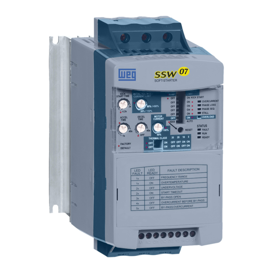
- Page 1 Motors | Energy | Automation | Coatings Soft-Starter Arrancador Suave Soft-Starter SSW-07 User's Guide Manual del Usuario Manual do Usuário...
- Page 2 SOFT-STARTER USER’S GUIDE MANUAL DEL USUARIO DEL ARRANCADOR SUAVE MANUAL DO USUÁRIO DA SOFT-STARTER Series: SSW-07 Document: 0899.5832 / 06 English - Español - Português 04/2009...
- Page 3 Summary of revisions / Sumario de las revisiones / Sumário das revisões The information below describes the revisions in this manual. Revision Descripcion Chapter First Edition General Revision General Revision Size 4 Included 5 and 6 Table 3.1 and 8.2 corrected 3 and 8 La información abajo describe las revisiones ocurridas en este manual.
-
Page 4: Table Of Contents
3.2.1 Power Terminals ............16 3.2.2 Location of the Grounding, Control and Power Connections ..............17 3.2.3 Recommended Power and Grounding Cables ....18 3.2.4 Power Supply Connection to the Soft-Starter SSW-07 18 3.2.4.1 Power Supply Capacity ........19 3.2.4.2 Recommended Fuses .........19 3.2.4.3 Recommended Contactors .........20 3.2.5 Soft-Starter SSW-07 Connection to the Motor .....20... - Page 5 7.1 IP20 Kit ................49 CHAPTER 8 Technical Characteristics 8.1 Nominal Powers and Currents According to UL508 ...50 8.2 Nominal Powers and Currents for Standard IP55, IV Pole Weg Motor .............50 8.3 Power Data .................51 8.4 Electronics and Programming Data ........51...
-
Page 6: Safety Notices In The Manual
1.3 PRELIMINARY RECOMMENDATIONS DANGER! Only personnel with suitable qualification and familiar with the Soft-Starter SSW-07 and associated equipment should plan or implement the installation, start-up, operation and maintenance of this equipment. These personnel must follow all safety instructions in this manual and/ or defined by local regulations. - Page 7 If necessary, first touch the grounded metallic heatsink or use a suitable grounded wrist strap. Do not apply any high voltage test on the Soft-Starter SSW-07! If necessary, contact the manufacturer. NOTE! Soft-Starters SSW-07 may interfere with other electronic equipment.
-
Page 8: General Information
These manuals are supplied in electronic format on the CD-ROM that accompanies the Soft-Starter, or can be obtained at WEG’s web site: http://www.weg.net. The Soft-Starter SSW-07 is a high performance product that permits 2.2 ABOUT THE the start control of the three phase AC induction motors. Thus, it... -
Page 9: Soft-Starter Ssw-07 Identification Plate
Three-Phase Outputs Digital Inputs Power Supply Power Supply 14/23 Digital Signal Processor Three-Phase Motor Figure 2.2 - Soft-Starter SSW-07 block diagram 2.3 SOFT-STARTER SSW-07 IDENTIFICATION PLATE SSW-07 Model WEG Stock Serial Number Item Number Software Version Manufacturing Input Data (Voltage,... - Page 10 Chapter 2 - GeNeraL INFOrMatION Position of the Identification Plate on the Soft-Starter SSW-07: FRONTAL VIEW X VIEW VISTA DE X VISTA FRONTAL Figure 2.4 - Location of the labels...
- Page 11 Chapter 2 - GeNeraL INFOrMatION...
-
Page 12: Receiving And Storage
Damage has occurred during transport. If so, contact the carrier immediately. If the Soft-Starter SSW-07 is not installed immediately, store it in its package in a clean and dry place with temperature between -25 °C (-13 °F) and 65 °C (149 °F). 1 hour at -40 °C (-40 °F) is permitted. -
Page 13: Installation And Connection
Soft-Starter SSW-07. The guidelines and suggestions must be followed for the correct operation of the Soft-Starter SSW-07. 3.1 MECHANICAL INSTALLATION The location of the Soft-Starters SSW-07 is an important factor to 3.1.1 Environmental assure the correct operation and high product reliability. Conditions Avoid: Direct exposure to sunlight, rain, high moisture and sea air ;... -
Page 14: Mounting Specifications
2) Do not put heat sensitive components immediately above the Soft-Starter SSW-07. ATTENTION! If a Soft-Starter SSW-07 is installed on top of another use the minimum distance A + B and diverge from the top Soft-Starter the hot air that comes from the one beneath it. -
Page 15: Mounting Inside A Panel
ENTRADA Inlet FLUXO DE AR Figure 3.2 - Free spaces for ventilation For Soft-Starters SSW-07 installed in panels or closed metallic 3.1.3.1 Mounting boxes exhaustion/cooling is required so the temperature does not Inside a Panel exceed the maximum allowed. Refer to dissipated nominal power in table 3.3. -
Page 16: Mounting On Surface
3.1.3.2 Mounting on Figure 3.3 shows the installation of the Soft-Starter SSW-07 on the Surface surface of a mounting plate. Figure 3.3 - Installation procedures of the Soft-Starter SSW-07 on a surface 3.2 ELECTRICAL INSTALLATION DANGER! The Soft-Starter SSW-07 cannot be used as an emergency stop device. -
Page 17: Power Terminals
R/1L1 S/3L2 T/5L3 U/2T1 V/4T2 W/6T3 PE Figure 3.4 - Standard power/grounding connections 3.2.1 Power The power terminal blocks vary in size and configuration, depending Terminals on the SSW-07 soft-starter model, as can be observed at the figures 3.5 and 3.6. Terminals: R / 1L1, S / 3L2 and T / 5L3: AC supply line. U / 2T1, V / 4T2 and W / 6T3: Motor connection. -
Page 18: Location Of The Grounding, Control And Power Connections
Power Terminal Terminal POTENCIA U/2T1 W/6T3 V/4T2 Models 17 A to 85 A Models 130 A to 412 A Figure 3.5 - Power terminals Line / Motor Grounding SSW-07 Enclosure Torque Torque Screw/ Model Size Screw Terminal (in lb) (in lb) -
Page 19: Recommended Power And Grounding Cables
Soft-Starter SSW-07. DANGER! Provide a power supply disconnecting switch for the Soft-Starter SSW-07. This disconnecting switch must disconnect the AC input voltage to the Soft-Starter SSW-07 whenever necessary (for example: during maintenance services). If a disconnected switch or a contactor is inserted in the motor supply line never operate these devices with the motor running or when the Soft-Starter SSW-07 is enabled. -
Page 20: Power Supply Capacity
The connector tightening torque is indicated in table 3.4. Use only copper wires 70 °C (158 °F). 3.2.4.1 Power Supply The Soft-Starter SSW-07 is suitable to be used in a circuit capable Capacity of supplying not more than X (according to table 3.6) symmetrical rms amperes, Y maximum volts when protected by ultra-rapid fuses. -
Page 21: Recommended Contactors
Motor DANGER! Power factor correction capacitors must never be installed at the output of the Soft-Starter SSW-07. (U / 2T1, V / 4T2 and W / 6T3). ATTENTION! To ensure that the protections based on the current reading and... -
Page 22: Standard Three-Wire Connection
Chapter 3 - INStaLLatION aND CONNeCtION 3.2.5.1 Standard Line current of the Soft-Starter SSW-07 is equal to the motor current. Three-Wire Connection 2/V1 5/V2 4/U2 2/V1 4/U2 6/W2 6/W2 1/U1 5/V2 1/U1 3/W1 3/W1 Figure 3.7 - Soft-Starter SSW-07 with standard connection 3.2.6 Grounding... -
Page 23: Control And Signal Connections
Chapter 3 - INStaLLatION aND CONNeCtION EMI - Electronic Interference The Soft-Starter SSW-07 is developed to be used in industrial systems (Class A) according to Standard EN60947-4-2. It’s necessary to have a distance of 0.25 m (10 in) between the Soft- Starter SSW-07 control cables and motor cables. - Page 24 In case of maintenance of the Soft-Starter SSW-07 or the motor it is necessary to remove the input fuses or disconnect the power supply to ensure the complete equipment disconnection from the power supply.
-
Page 25: Recommended Set-Up With Command Via Two-Wire
Chapter 3 - INStaLLatION aND CONNeCtION 3.3.1 Recommended Set-up with Command via Two-wire Digital Inputs and Isolation Contactor R S T Refer to notes in item 3.3. U V W Figure 3.10 - Recommended set-up with commands via two-wire digital inputs and isolation contactor 3.3.2 Recommended Set-up with... -
Page 26: Symbols
Chapter 3 - INStaLLatION aND CONNeCtION 3.3.3 Symbols Electrical connection between Fuse two signals Connection terminals Thyristor/SCR Relay or contactor coil Three-phase motor Normally open contact (NO) Transformer Indicator light N.O Contact (with retention) Circuit-breaker Normally closed (NC) (opens under load) push-button Resistor Normally open (NO) -
Page 27: Setting The Ssw-07
Voltage Ramp Starting: This is the most commonly used method. Very easy to program and set. The Soft-Starter SSW-07 imposes the voltage applied to the motor. Generally applied to loads with a lower initial torque or a square torque. This kind of control can be used as an initial working test. -
Page 28: Kick Start
Kick Start Enabling DIP Switch Figure 4.2 - Kick Start enabling Soft-Starter SSW-07 offers a Kick Start function for loads that present a large initial resistance to movement. This function is enabled through the Kick Start DIP Switch. The duration of the voltage pulse is set through the trimpot Kick Start Time. -
Page 29: Current Limit Setting
SETTING If the current limit is reached during the start of the motor, Soft- Starter SSW-07 will maintain the current at this limit until the motor reaches nominal speed. If the current limit is not reached, the motor will start immediately. -
Page 30: Acceleration Ramp Time Setting
Please consider that in cases where the relation of the SSW-07 current and the motor nominal current is 1.00, the maximum time that the SSW-07 can work with 3 x In is 30 seconds. 4.6 DECELERATION Enables and sets the time of voltage decrease. -
Page 31: Motor Current Setting
Chapter 4 - SettING the SSW-07 Deceleration Ramp Time Setting Trimpot Figure 4.6 - Deceleration ramp time setting 4.7 MOTOR This setting defines the ratio of the SSW-07 current and the motor CURRENT current. The value of the setting is very important since it defines SETTING the protection of the motor driven by the SSW-07. The setting of this function interferes directly in the following motor protections: -Overload; -Overcurrent; -Stall; -Phase loss. Calculation Example: SSW-07 Used: 30 A Motor Used: 25 A... -
Page 32: Motor Electronic Overload Protection
Chapter 4 - SettING the SSW-07 Motor Current Setting Trimpot Figure 4.7 - Motor current setting 4.8 MOTOR The motor electronic overload protection simulates the heating and ELECTRONIC cooling of the motor, also known as thermal image. This simulation OVERLOAD uses as input data the True rms current. - Page 33 4.2 - Motor protection thermal class time in cold condition at S.F.=1.15 NOTES! When SSW-07 is without the electronic supply voltage (A1 and A2), the thermal image is saved internally. When the supply (A1 and A2) is re-established, the thermal image value returns to the value prior to the electronic supply loss.
- Page 34 Chapter 4 - SettING the SSW-07 Time t(s) 1000 Class 30 Class 25 Class 20 Class 15 Class 10 Class 5 x In motor Current 9x S.F.=1 Figure 4.9 - Motor protection thermal classes in hot condition at 100 % ln...
-
Page 35: Reset
A fault condition can be reset using the RESET key at the front of 4.9 RESET the SSW-07 or through a push-button (0.5 seconds) at DI3 (digital input for RESET). Another way to reset the SSW-07 is by switching Off/On the electronic power supply (A1 and A2). NOTE! -
Page 36: Output Relay Operation
SSW-07 input. Refer to figure 3.3.2. In order to change the relay output RL1 programming follow these instructions: 1. To enter in programming mode keep the reset key, at the SSW-07 front cover, pressed during 5 seconds, keeping it also pressed throughout the programming; 2. When in the programming mode two LEDs turn on (Overcurrent and Phase Loss), indicating that DI2 is programmed for Error Reset. -
Page 37: Programming Information And Suggestions
ATTENTION! To know the correct programming of the parameters, have your load data on hand and use the WEG (Soft-Starter) Dimensioning Software available at WEG’s home page (http://www.weg.net). If you are unable to use the software mentioned above, you can follow some practical concepts described in this chapter. -
Page 38: Voltage Ramp Starting
Chapter 5 - prOGraMMING INFOrMatION aND SUGGeStIONS I/In T/Tn Current Torque Figure 5.2 - Characteristic curves of torque and current in a current limitation start 5.1.1 Voltage Ramp 1) Set the value of the initial voltage to a low value; Starting 2) When a load is applied to the motor, set the initial voltage to a value that makes the motor rotate smoothly from the instant it is... -
Page 39: Current Limit Starting
Chapter 5 - prOGraMMING INFOrMatION aND SUGGeStIONS 5.1.2 Current Limit 1) To start with a current limitation it is necessary to start with a load. Starting Initial test without load can be done with a voltage ramp; 2) Set the acceleration time with the necessary starting time, initially with short times, 20 to 25 seconds. -
Page 40: Protections And Programming
Chapter 5 - prOGraMMING INFOrMatION aND SUGGeStIONS 5.2 PROTECTIONS PROGRAMMING 5.2.1 Suggestion on 1) Initially start at the standard thermal class, sometimes, but without How to Program the motor overheating; the Thermal Class 2) Determine the correct starting time. Find an average of the current using a multmeter with a current probe to measure it;... - Page 41 NOTE! Remember that this protection has as a standard the Three Phase IP55 Standard WEG Motor, therefore if your motor is different, then do not program the thermal class to its maximum, instead, program it near its minimum thermal class to start.
-
Page 42: Time Reduction From Cold To Hot Starting
Chapter 5 - prOGraMMING INFOrMatION aND SUGGeStIONS Example of how setting the thermal class: Motor data: Power: 50 hp Voltage: 380 V Nominal Current (ln): 71 A Service Factor (S.F.): 1.00 lp/ln: 6.6 Stall time: 12 s in hot condition Speed: 1770 rpm Motor + load starting data: Starting by Voltage Ramp, starting current average: 3 x the nominal current of the motor during 25 s (3 x ln @ 25 s). 1) In the graph, figure 4.8 in cold condition, one can see the minimum Thermal Class that will allow the start with a reduced voltage: For 3 x ln of the motor @25 s, the next highest is adopted: Class 10. -
Page 43: Service Factor
Chapter 5 - prOGraMMING INFOrMatION aND SUGGeStIONS 5.2.3 Service Factor When the Service Factor (S.F.) is different from 1.00 and if there is a need to use it, one can check in the graph, in cold condition, the points for S.F.=1.15 and in the table for S.F.=1.15. If one wishes to know the thermal protection working times for other S.F. - Page 44 In _ of _ Motor x S.F. Motor _ Current = x 100 In _ of _ SSW Example: Motor with 80 A and S.F.=1.25 SSW-07 of 130 A 80 x 1.25 x 100 = 77 % The Motor Current trimpot must then be set to 77 %. NOTE! The example and equation above must only be used when the service factor is used, and if the parameter of the service factor is not programmable via the optional keypad or serial communication.
-
Page 45: Solutions And Troubleshooting
This procedure is performed in the following ways: Disconnecting and reapplying the AC power (power-on RESET); Pressing the “RESET” key in the SSW-07 front panel (RESET key); Automatically by the automatic RESET. Enable this function via DIP Switch (auto);... - Page 46 Overcurrent It is only monitored when the Momentary motor overload. SSW-07 is at full voltage. When Motor shaft is locked, rotor blocked. the parameters are set with Power-on. the factory default values this Reset key.
- Page 47 Chapter 6 - SOLUtION aND trOUBLeShOOtING Protection Description and Activation Description Probable Causes Reset Fault Display Undervoltage Activates when the control Electronics supply lower than the in the control supply voltage is lower than 93 minimum value. supply Vac. Electronics power supply with loose contact.
-
Page 48: Troubleshooting
Reduce the acceleration ramp time. acceleration table 6.2 - Solving the most frequent problems NOTE! When contacting WEG for service or technical assistance, please have the following data on hand: Model of the Soft-Starter; Serial number, production date and hardware revision present in the identification label of the product (refer to item 2.3);... -
Page 49: Preventive Maintenance
6.3 PREVENTIVE MAINTENANCE WARNING! Always disconnect the general power supply before touching any electric component associated to the Soft-Starter SSW-07. Do not apply any high voltage tests on the Soft-Starter SSW-07! If necessary, consult the manufacturer. Do not use megometers to test thyristors. -
Page 50: Options And Accessories
Optional Description WEG Part Number Plug-in Local Keypad 10935572 Remote Keypad Kit 10935649 1 m SSW-07 - Remote HMI Connection Cable 10050268 2 m SSW-07 - Remote HMI Connection Cable 10190951 3 m SSW-07 - Remote HMI Connection Cable 10211478... -
Page 51: Technical Characteristics
412 A table 8.2 - Powers and currents for WEG motors NOTE! The maximum powers indicated in table 8.1 are based on 3 x nominal current of Soft-Starter SSW-07 during 30 s and 10 starts per hour (3xIn @ 30 s). -
Page 52: Power Data
Maximum number of starts per hour 10 (1 every 6 minutes; models from 45 A to 200 A) with optional ventilation Kit Start cycle 3 x In of the SSW-07 during 30 seconds Thyristors (SCRs) Reverse voltage with 1600 V maximum peak Overvoltage category III (UL508/EN61010) 8.4 ELECTRONICS AND PROGRAMMING DATA...
Need help?
Do you have a question about the SSW-07 and is the answer not in the manual?
Questions and answers