
Related Manuals for WEG SSW900-CAN-W


Summary of Contents for WEG SSW900-CAN-W
- Page 1 Motors | Automation | Energy | Transmission & Distribution | Coatings CANopen SSW900-CAN-W User’s Guide...
- Page 2 CANopen User’s Guide Series: SSW900 Software version: 1.2X Language: English Document: 10006223748 / 00 Build 5251 Publication Date: 01/2019...
- Page 3 Summary of Revisions The information below describes the reviews made in this manual. Version Revision Description V1.2X First edition...
-
Page 4: Table Of Contents
Contents CONTENTS ABOUT THE MANUAL ..................ABBREVIATIONS AND DEFINITIONS . - Page 5 Contents 8.1.3 Object 1018h - Identity Object ..............24 8.2 SERVICE DATA OBJECTS - SDOS .
-
Page 6: About The Manual
ABOUT THE MANUAL ABOUT THE MANUAL This manual supplies the necessary information for the operation of the SSW900 soft-starter using the CANopen protocol. This manual must be used together with the SSW900 user’s manual and programming manual. ABBREVIATIONS AND DEFINITIONS ASCII American Standard Code for Information Interchange Controller Area Network... -
Page 7: Main Characteristics
MAIN CHARACTERISTICS 1 MAIN CHARACTERISTICS Below are the main characteristics for communication of the soft-starter SSW900 with CANopen accessory. Network management task (NMT). 4 transmission PDOs. 4 reception PDOs. Heartbeat Consumer. Heartbeat Producer. Node Guarding. SDO Client. SYNC producer/consumer. It is supplied with an EDS file for the network master configuration. Acyclic data available for parameterization. -
Page 8: Interface Description
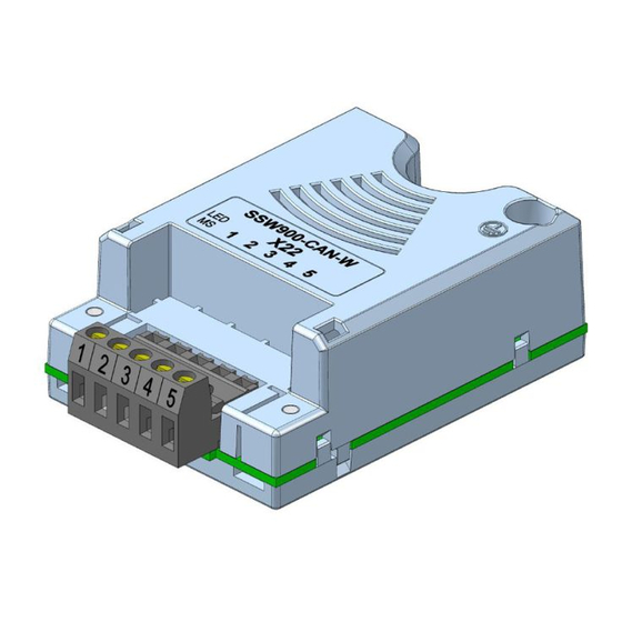
The accessories can be connected to any Slot, but only one type of each communication accessory is allowed. Read the user’s manual of the SSW900 soft-starter before installing or using this accessory. Slot 1 Slot 2 Figure 2.1: Slots for accessories 2.1 CANOPEN ACCESSORY SSW900-CAN-W: Supplied items: – Installation guide. – CANopen/DeviceNet communication module. -
Page 9: Power Suplly
INTERFACE DESCRIPTION Table 2.1: Pin assignment of connector for CANopen interface Name Function Negative pole of the power supply CAN_L Communication signal CAN_L Shield Cable shield CAN_H Communication signal CAN_H Positive pole of the power supply 2.3 POWER SUPLLY The power supply of the network must be able to supply enough current to power up the equipments and interfaces connected to the network. -
Page 10: Canopen Network Installation
CANOPEN NETWORK INSTALLATION 3 CANOPEN NETWORK INSTALLATION The CANopen network, such as several industrial communication networks, for being many times applied in aggressive environments with high exposure to electromagnetic interference, requires that certain precautions be taken in order to guarantee a low communication error rate during its operation. Recommendations to perform the connection of the product in this network are presented next. -
Page 11: Connection In The Network
CANOPEN NETWORK INSTALLATION Table 3.2: CANopen cable characteristics Cable Length (m) Resistence per Meter (mΩ/m) Conductor Cross Section (mm 0 ... 40 0.25 ... 0.34 40 ... 300 <60 0.34 ... 0.60 300 ... 600 <40 0.50 ... 0.60 600 ... 1000 <26 0.75 ... -
Page 12: Status
S STATUS 4 S STATUS Allows viewing of the SSW reading variables. S5 COMMUNICATIONS HMI monitoring parameters of the communication interfaces. For a detailed description, refer to the Anybus-CC, CANopen, DeviceNet and Modbus RTU User’s Manuals of the SSW according to the interface used. S5.1 Status Word .1 SSW 0 ... -
Page 13: S5.3 Value For Outputs
S STATUS Description: Command word of all sources of the SSW. The RUN/STOP and JOG commands of the sources which are not active will be reset. .5 Slot1 Control word via any communication accessory connected to Slot 1. .6 Slot2 Command word via any communication accessory connected to Slot 2. Value/Description Bit 0 0: stopping by ramp. -
Page 14: S5.7 Canopen/Devicenet
S STATUS S5.7 CANopen/DeviceNet .1 CAN Controller Status 0 ... 6 .2 Received Telegram 0 ... 65535 .3 Transmitted Telegram 0 ... 65535 .4 Bus Off Counter 0 ... 65535 .5 Lost Messages 0 ... 65535 .6 CANopen Comm. Status 0 ... - Page 15 S STATUS Indication Description 0 = Disabled CANopen protocol disabled. 1 = Initialization Communication with the device is not possible during this stage, which is concluded automatically. 2 = Stopped Only the NMT object is available. 3 = Operational All the communication objects are available. 4 = PreOperational It is already possible to communicate with the slave but its PDOs are not yet available for operation.
-
Page 16: Configurations
SSW900-CPN-IO-N For further details regarding the SSW configuration to operate these protocols, refer to the SSW Communication Manual. C8.4 CANopen/DeviceNet Configuration for the SSW900-CAN-W communication accessory and protocols that use this interface. C8.4 CANopen/DeviceNet C8.4.1 Protocol Range: 0 ... 2... - Page 17 C CONFIGURATIONS Description: It allows programming the address used for the CAN communication. It is necessary that each element of the network has an address different from the others. The valid addresses for this parameter depend on the protocol programmed in P0700: P0700 = 1 (CANopen): valid addresses: 1 to 127.
-
Page 18: C8.4.5 Can Error
The actions described in this parameter are executed through the writing of the respective bits in the control word of the SLOT to which the accessory SSW900-CAN-W is connected. Thus, for the commands to be effective, the equipment must be programmed to be controlled by the network interface used. This programming is done through menu C3. -
Page 19: Operation In The Canopen Network
OPERATION IN THE CANOPEN NETWORK 6 OPERATION IN THE CANOPEN NETWORK 6.1 ACCESS TO THE DATA Each slave of the CANopen network has a list called object dictionary that contains all the data accessible via network. Each object of this list is identified with an index, which is used during the equipment configuration as well as during message exchanges. -
Page 20: Cob-Id
This file is used by a master or configuration software to program devices present at CANopen network. The EDS file is available from WEG website (http://www.weg.net). It is important to note if the EDS configuration file is compatible with the firmware version of the SSW900 soft-starter. -
Page 21: Object Dictionary
OBJECT DICTIONARY 7 OBJECT DICTIONARY The object dictionary is a list containing several equipment data which can be accessed via CANopen network. An object of this list is identified by means of a 16-bit index, and it is based in that list that all the data exchange between devices is performed. -
Page 22: Manufacturer Specific Objects
OBJECT DICTIONARY Table 7.2: Object list – Communication Profile Index Object Name Type Access 1000h device type UNSIGNED32 1001h error register UNSIGNED8 1005h COB-ID SYNC UNSIGNED32 100Ch quard time UNSIGNED16 100Dh life time factor UNSIGNED8 1016h ARRAY consume heartbeat time UNSIGNED32 1017h producer heartbeat time... -
Page 23: Communication Objects Description
COMMUNICATION OBJECTS DESCRIPTION 8 COMMUNICATION OBJECTS DESCRIPTION This item describes in detail each of the communication objects available for the SSW900 soft-starter. It is necessary to know how to operate these objects to be able to use the available functions for the SSW900 soft-starter communication. -
Page 24: Object 1018H - Identity Object
COMMUNICATION OBJECTS DESCRIPTION 8.1.3 Object 1018h - Identity Object It brings general information about the device. Table 8.4: Object 1018h - Identity Object Index Sub- Name Type Access Value index Mapping Number of the last sub-index UNSIGNED8 Vendor ID UNSIGNED32 0000.0123h 1018h Product code... -
Page 25: Sdos Operation
COMMUNICATION OBJECTS DESCRIPTION 8.2.2 SDOs Operation A telegram sent by an SDO has an 8 byte size, with the following structure: Identifier 8 data bytes Command Index Subindex Object data 11 bits byte 0 byte 1 byte 2 byte 3 byte 4 byte 5 byte 6... -
Page 26: Process Data Objects - Pdos
COMMUNICATION OBJECTS DESCRIPTION Identifier Command Index Subindex Data 601h The slave responds to the request indicating that the value of the referred object is equal to 999 Identifier Command Index Subindex Data 581h 8.3 PROCESS DATA OBJECTS - PDOS The PDOs are used to send and receive data used during the device operation, which must often be transmitted in a fast and efficient manner. -
Page 27: Receive Pdos
COMMUNICATION OBJECTS DESCRIPTION The EDS file brings the list of all objects available, informing whether the object can be mapped or not. 8.3.2 Receive PDOs The receive PDOs, or RPDOs, are responsible for receiving data that other devices send to the CANopen network. The soft-starter SSW900 has 4 receive PDOs, each one being able to receive up to 8 bytes. -
Page 28: Transmit Pdos
COMMUNICATION OBJECTS DESCRIPTION PDO_MAPPING Index Sub- Name Type Access Value index Mapping Number of mapped objects 0 = disable 1-4=number of mapped objects 1600h até 1603h 1 up to 1 up to 4 object mapped in the PDO UNSIGNED32 According EDS file This parameter indicates the mapped objects in the SSW900 soft-starter receive PDOs. - Page 29 COMMUNICATION OBJECTS DESCRIPTION Index Sub- Name Type Access Value index Mapping Number of the last sub-index UNSIGNED8 COB-ID used by the PDO UNSIGNED32 180h / 280h / 380h / 480h + Node-ID 1800h-1803h Transmission Type UNSIGNED8 Time between transmissions UNSIGNED16 Reserved UNSIGNED8 Event timer...
-
Page 30: Synchronization Object - Sync
COMMUNICATION OBJECTS DESCRIPTION UNSIGNED32 Index (16 bits) Sub-index (8 bits) Object size (8 bits) For instance, analyzing the standard mapping of the fourth transmit PDO, we have: Sub-índice 0 = 2: This PDO has two mapped objects. Sub-índice 1 = 22A8.0010h: the first mapped object has an index equal to 22A8h, sub-index 0 (zero), and a size of 16 bits. -
Page 31: Network Management - Nmt
COMMUNICATION OBJECTS DESCRIPTION ✓ NOTE! The period of the SYNC telegrams must be programmed in the producer according to the transmission rate and the number of synchronous PDOs to be transmitted. There must be enough time for the transmission of these objects, and it is also recommended that there is a tolerance to make it possible the transmission of asynchronous messages, such as EMCY, asynchronous PDOs and SDOs. -
Page 32: Error Control - Node Guarding
COMMUNICATION OBJECTS DESCRIPTION for operation. In the operational state all the objects are available, whereas in the stopped state only the NMT object can receive or transmit telegrams to the network. The next table shows the objects available for each state. Table 8.11: Objects accessible in each state Initialization Préoperational... - Page 33 COMMUNICATION OBJECTS DESCRIPTION CANopen Periodic Master Request Response Communication failure Request Error! Error! Timeout waiting Timeout waiting for the response for the request Figure 8.5: Error control service – Node Guarding There are two objects of the dictionary for the configuration of the error detection times for the Node Guarding service: Index Sub- Name...
-
Page 34: Error Control - Heartbeat
COMMUNICATION OBJECTS DESCRIPTION ✓ NOTE! This object is active even in the stopped state (see table 8.11). The value 0 (zero) in any of these two objects will disable this function. If after the error detection the service is enabled again, then the error indication will be removed from the HMI. -
Page 35: Initialization Procedure
COMMUNICATION OBJECTS DESCRIPTION UNSIGNED32 Reserved (8 bits) Node-ID (8 bits) HeartBeat time (16 bits) Node-ID: it allows programming the Node-ID for the heartbeat producer to be monitored. Heartbeat time: it allows programming the time, in 1 millisecond multiples, until the error detection if no message of the producer is received. - Page 36 COMMUNICATION OBJECTS DESCRIPTION Configuration of all device parameters via SDO Initiates the transmission of the SYNC object (optional) Initiates the Guarding or Heartbeat error control protocol (optional) Commands the network devices to the operational state Figure 8.7: Initialization process flowchart It is necessary to observe that the SSW900 soft-starter communication objects (1000h to 1FFFh) are not stored in the nonvolatile memory.
-
Page 37: Startup Guide
Operational. It is in this condition that PDO transmission and reception effectively occurs. The EDS file is available from WEG website (http://www.weg.net). It is important to note if the EDS configuration file is compatible with the firmware version of the SSW900 soft-starter. -
Page 38: Communication Status
STARTUP GUIDE 9.4 COMMUNICATION STATUS Once the network is assembled and the client programmed, it is possible to use the MS LED and parameters of the equipment to identify some status related to the communication. The MS LED provides information about the status of the interface. The parameters S5.7.6 and S5.7.7 indicate the status of CANopen communication. -
Page 39: 10Faults And Alarms
FAULTS AND ALARMS 10 FAULTS AND ALARMS Fault/Alarm Description Possible Causes F133/A133: CAN Interface without It indicates that the CAN interface does not have - Measure the voltage between the pins 1 and 5 of the Power Supply power supply between the pins 1 and 5 of the CAN interface connector. - Page 40 APPENDIX A Level 1 Level 2 Level 3 Page Status Measurements S1.1 Current S1.2 Main Line Voltage S1.3 Output Voltage S1.4 SCR Blocking Voltage S1.5 Output Power & P.F. S1.6 P.L.L. S1.7 Motor Torque S1.8 Control Voltage S2.1 Digital S2.2 Analog Output SSW900 S3.1...
- Page 41 Level 1 Level 2 Level 3 Page Configurations Starting and Stopping Nominal Motor Data LOC/REM Selection C4.1 Digital Inputs C4.2 Digital Outputs C4.3 Analog Output Protections C5.1 Voltage Protections C5.2 Current Protections C5.3 Torque Protections C5.4 Power Protections C5.5 Phase Sequence C5.6 Bypass Protections C5.7...
- Page 42 Table A.2: Characteristics of the parameters for the communication protocol Parameter Description Range of values Decimal Index Net Id Size places S1 Status\Measurements S1.1 Current S1.1.1 R Phase 0.0 to 14544.0 A 201Ah 32bit S1.1.2 S Phase 0.0 to 14544.0 A 201Ch 32bit S1.1.3...
- Page 43 Parameter Description Range of values Decimal Index Net Id Size places S2.1.1 Inputs 22A5h 16bit Bit 0 = DI1 Bit 1 = DI2 Bit 2 = DI3 Bit 3 = DI4 Bit 4 = DI5 Bit 5 = DI6 Bit 6 ... 15 = Reserved S2.1.2 Outputs 22A6h...
- Page 44 Parameter Description Range of values Decimal Index Net Id Size places S3.1.3 Status Word S3.1.3.1 22A8h 16bit Bit 0 = Running Bit 1 = Gener. Enabled Bit 2 = JOG Bit 3 = Initial Test Bit 4 = Ramp Up Bit 5 = Full Voltage Bit 6 = Bypass Bit 7 = Ramp Down...
- Page 45 Parameter Description Range of values Decimal Index Net Id Size places 6 = 1100 to 1400 A S3.3.2 Voltage 2128h enum 0 = 220 to 575 V 1 = 400 to 690 V S3.3.3 Control Voltage 2129h enum 0 = 110 to 240 V 1 = 110 to 130 V 2 = 220 to 240 V 3 = 24 Vcc...
- Page 46 Parameter Description Range of values Decimal Index Net Id Size places S5.1 Status Word S5.1.1 22A8h 16bit Bit 0 = Running Bit 1 = Gener. Enabled Bit 2 = JOG Bit 3 = Initial Test Bit 4 = Ramp Up Bit 5 = Full Voltage Bit 6 = Bypass Bit 7 = Ramp Down...
- Page 47 Parameter Description Range of values Decimal Index Net Id Size places Bit 1 = Gener. Enabled Bit 2 = JOG Bit 3 = FWD/REV Bit 4 = LOC/REM Bit 5 ... 6 = Reserved Bit 7 = Reset Bit 8 ... 15 = Reserved S5.2.5 Slot1 22ADh...
- Page 48 Parameter Description Range of values Decimal Index Net Id Size places 19 = EtherNet/IP 20 = Reserved 21 = Modbus TCP 22 = Reserved 23 = PROFINET IO 24 ... 25 = Reserved S5.5.2 Comm. Status 22EFh enum 0 = Setup 1 = Init 2 = Wait Comm 3 = Idle...
- Page 49 Parameter Description Range of values Decimal Index Net Id Size places 1 = Initialization 2 = Stopped 3 = Operational 4 = PreOperational S5.7.8 DNet Network Status 22CCh enum 0 = Offline 1 = OnLine,NotConn 2 = OnLine,Conn 3 = Conn.Timed-out 4 = Link Failure 5 = Auto-Baud S5.7.9...
- Page 50 Parameter Description Range of values Decimal Index Net Id Size places S6.4.16 User #16 -10000 to 10000 2474h 1140 s32bit S6.4.17 User #17 -10000 to 10000 2476h 1142 s32bit S6.4.18 User #18 -10000 to 10000 2478h 1144 s32bit S6.4.19 User #19 -10000 to 10000 247Ah 1146...
- Page 51 Parameter Description Range of values Decimal Index Net Id Size places D4.1 Start Current D4.1.1 Maximum 0.0 to 14544.0 A 2024h 32bit D4.1.2 Average 0.0 to 14544.0 A 2026h 32bit D4.2 Real Start Time D4.2.1 Actual 0 to 999 s 2030h 16bit D4.2.2...
- Page 52 Parameter Description Range of values Decimal Index Net Id Size places C1.6 Current Ramp Time 1 to 99 % 2070h 8bit C1.7 Current Limit 150 to 500 % 206Eh 16bit C1.8 Start Torque Chara. 2078h enum 1 = Constant 2 = Linear 3 = Square C1.9 Initial Start Torque...
- Page 53 Parameter Description Range of values Decimal Index Net Id Size places 0 = HMI Keys 1 = DIx 2 = USB 3 = SoftPLC 4 = Slot 1 5 = Slot 2 C3.4 Commands Copy 20E7h enum 0 = No 1 = Yes C4 Configurations\I/O C4.1...
- Page 54 Parameter Description Range of values Decimal Index Net Id Size places 8 = No External Fault 9 = No External Alarm 10 = Brake 11 = Reset 12 = Load User 1/2 13 = Reserved 14 = Emergency Start 15 ... 16 = Reserved C4.1.4 210Ah enum...
- Page 55 Parameter Description Range of values Decimal Index Net Id Size places 12 = Load User 1/2 13 ... 14 = Reserved 15 = Mot. Thermistor A032 16 = Mot. Thermistor F032 C4.2 Digital Outputs C4.2.1 2113h enum 0 = Not Used 1 = Running 2 = Full Voltage 3 = Bypass...
- Page 56 Parameter Description Range of values Decimal Index Net Id Size places 12 = Communication 13 = I motor % > Value 14 = Breaker Shunt Trip C4.2.4 DO Comparison Value 10.0 to 500.0 % 2116h 16bit C4.3 Analog Output C4.3.1 Function 20FBh enum...
- Page 57 Parameter Description Range of values Decimal Index Net Id Size places C5.2 Current Protections C5.2.1 Motor Undercurrent C5.2.1.1 Mode 238Eh enum 0 = Inactive 1 = Fault F065 2 = Alarm A065 C5.2.1.2 Level 0 to 99 %In 238Fh 8bit C5.2.1.3 Time 1 to 99 s...
- Page 58 Parameter Description Range of values Decimal Index Net Id Size places 0 = Inactive 1 = Fault F081 2 = Alarm A081 C5.4.2.2 Level 0 to 99 %Pn 23C4h 8bit C5.4.2.3 Time 1 to 99 s 23C5h 8bit C5.5 Phase Sequence C5.5.1 Mode 23A2h...
- Page 59 Parameter Description Range of values Decimal Index Net Id Size places C5.8.5 Ch2 Sensor Fault C5.8.5.1 Mode 23E7h enum 0 = Fault F110 and F118 1 = Alarm A110 and A118 C5.8.6 Ch2 Overtemperature C5.8.6.1 Mode 23CAh enum 0 = Fault F102 1 = Alarm A102 2 = F102 and A102 ◦...
- Page 60 Parameter Description Range of values Decimal Index Net Id Size places C5.8.13.1 Mode 23F2h 1010 enum 0 = Off 1 = On 2 = On Stator C5.8.14 Ch5 Sensor Fault C5.8.14.1 Mode 23EAh 1002 enum 0 = Fault F113 and F121 1 = Alarm A113 and A121 C5.8.15 Ch5 Overtemperature...
- Page 61 Parameter Description Range of values Decimal Index Net Id Size places 0 = Automatic 1 = Class 10 2 = Class 15 3 = Class 20 4 = Class 25 5 = Class 30 6 = Class 35 7 = Class 40 8 = Class 45 C5.9.7 Motor Data...
- Page 62 Parameter Description Range of values Decimal Index Net Id Size places C6.2.1 Language 20C9h enum 0 = Português 1 = English 2 = Español C6.3 Date and Time C6.3.2 Day of the Week 20C3h enum 0 = Sunday 1 = Monday 2 = Tuesday 3 = Wednesday 4 = Thursday...
- Page 63 Parameter Description Range of values Decimal Index Net Id Size places C7.4.1 Mode 21F4h enum 0 = Inactive 1 = Reverse 2 = Optimal 3 = DC C7.4.2 Time 1 to 299 s 21F5h 16bit C7.4.3 Level 30 to 70 % 21F6h 8bit C7.4.4...
- Page 64 Parameter Description Range of values Decimal Index Net Id Size places C8.1.1.38 Word #34 0 to 65535 2535h 1333 16bit C8.1.1.39 Word #35 0 to 65535 2536h 1334 16bit C8.1.1.40 Word #36 0 to 65535 2537h 1335 16bit C8.1.1.41 Word #37 0 to 65535 2538h 1336...
- Page 65 Parameter Description Range of values Decimal Index Net Id Size places 1 = 19200 bits/s 2 = 38400 bits/s 3 = 57600 bits/s C8.2.4 Bytes Config. 22DDh enum 0 = 8 bits, no, 1 1 = 8 bits, even,1 2 = 8 bits, odd, 1 3 = 8 bits, no, 2 4 = 8 bits, even,2 5 = 8 bits, odd, 2...
- Page 66 Parameter Description Range of values Decimal Index Net Id Size places 11 = 255.224.0.0 12 = 255.240.0.0 13 = 255.248.0.0 14 = 255.252.0.0 15 = 255.254.0.0 16 = 255.255.0.0 17 = 255.255.128.0 18 = 255.255.192.0 19 = 255.255.224.0 20 = 255.255.240.0 21 = 255.255.248.0 22 = 255.255.252.0 23 = 255.255.254.0...
- Page 67 Parameter Description Range of values Decimal Index Net Id Size places 1 = Automatic C8.4.5 CAN Error C8.4.5.1 Mode 22D3h enum 0 = Inactive 1 = Fault 2 = Alarm C8.4.5.2 Alarm Action 22D4h enum 0 = Indicates Only 1 = Ramp Stop 2 = General Disable 3 = Change to LOC 4 = Change to REM...
- Page 68 Parameter Description Range of values Decimal Index Net Id Size places C9.3.1 Slot 1 2151h enum 0 = Automatic 1 = Anybus-CC 2 = RS-485 3 = PT100 4 = I/Os Exp. 5 = Profibus 6 = CAN 7 = Ethernet 8 = External Current Acqu.
- Page 69 Parameter Description Range of values Decimal Index Net Id Size places 8 = Thermal Class Status C10.4 Load Factory Default C10.4.1 Mode 20CCh enum 0 = No 1 = Yes C10.5 Save Changed Param. C10.5.1 Mode 20D1h enum 0 = No 1 = Yes C11 Configurations\SoftPLC C11.1...
- Page 70 Parameter Description Range of values Decimal Index Net Id Size places C11.3.32 User #32 -10000 to 10000 2494h 1172 s32bit C11.3.33 User #33 -10000 to 10000 2496h 1174 s32bit C11.3.34 User #34 -10000 to 10000 2498h 1176 s32bit C11.3.35 User #35 -10000 to 10000 249Ah 1178...
- Page 71 Table A.3: Description of the parameter data types Data Type Description enum Enumerated type (unsigned 8-bit) contains a list of values with function description for each item. 8bit Unsigned 8-bit integer, ranges from 0 to 255. 16bit Unsigned 16-bit integer, ranges from 0 to 65,535. s16bit Signed 16-bit integer, ranges from -32,768 to 32,767.
- Page 72 WEG Drives & Controls - Automação LTDA. Jaraguá do Sul – SC – Brazil Phone 55 (47) 3276-4000 – Fax 55 (47) 3276-4020 São Paulo – SP – Brazil Phone 55 (11) 5053-2300 – Fax 55 (11) 5052-4212 automacao@weg.net www.weg.net...
Need help?
Do you have a question about the SSW900-CAN-W and is the answer not in the manual?
Questions and answers