Table of Contents

Related Manuals for HMS H6996


Summary of Contents for HMS H6996
- Page 1 ORBITREK MAGNETYCZNY - MAGNETIC ELLIPTICAL BIKE - MAGNETICKÝ ORBITREK – MAGNETISCHER CROSSTRAINER H6996 INSTRUKCJA UŻYTKOWANIA – MANUAL INSTRUCTION NÁVOD K OBSLUZE – BEDIENUNGSANLEITUNG...
-
Page 2: Uwagi Dotyczące Bezpieczeństwa
UWAGI DOTYCZĄCE BEZPIECZEŃSTWA Przed rozpoczęciem treningu skonsultuj się z lekarzem w celu stwierdzenia braku przeciwwskazań do korzystania ze sprzętu do ćwiczeń. Decyzja lekarza jest niezbędna w przypadku przyjmowania leków wpływających na pracę serca, ciśnienie krwi i poziom cholesterolu. Jest to także konieczne w przypadku osób w wieku powyżej 35 lat oraz osób mających kłopoty ze zdrowiem. -
Page 3: Dane Techniczne
13. Sprzęt zaliczony został do klasy HC według normy EN ISO 20957-1 i jest przeznaczony wyłącznie do użytku domowego. Nie może być używany w celach terapeutycznych, rehabilitacyjnych i komercyjnych. 14. Podczas podnoszenia lub przenoszenia sprzętu zwracaj szczególną uwagę aby nie uszkodzić kręgosłupa. 15. - Page 4 Schemat szczegółowy:...
-
Page 5: Lista Części
Lista części Iloś Iloś Opis Opis ć ć 1 ZAŚLEPKA 48 ŁOŻYSKO 6203 2 CZUJNIK POMIARU PULSU 49 MAGNES 3 LEWY GÓRNY DRĄŻEK KIEROWNICY 50 SILNIK 4 PRZEWÓD CZUJNIKA POMIARU PULSU 2 51 TULEJA STALOWA 5 KOMPUTER 52 CZUJNIKI 6 PRZEWÓD CZUJNIKA POMIARU PULSU 53 KOŁO PASOWE φ260 KOMPUTERA 7 GÓRNY PRZEWÓD SILNIKOWY... - Page 6 36 LEWA TARCZA 83 KLUCZ SZEŚCIOKĄTNY 5mm 37 WSPORNIK KRZYŻOWY 84 KLUCZ SZEŚCIOKĄTNY 6mm 38 PŁASKA PODKŁADKA Ф16 85 ADAPTER 39 ŚRUBA ST4 86 PRZEWÓD DC 87 ŚRUBA 40 LEWA POKRYWA GŁÓWNA 41 PRAWA POKRYWA GŁÓWNA DRĄŻEK 88 PRAWY GÓRNY KIEROWNICY 42 ŚRUBA ST4 89 PRAWY...
- Page 7 Ilość Ilość Opis Opis Prawy górny drążek kierownicy 90 Podstawa prawego pedału 88 Lewy górny drążek kierownicy 30 Pedał lewy 91 Pedał prawy Komputer Kierownica 45 Stabilizator tylny 16 Lewy dolny drążek kierownicy 63 Rama 89 Prawy dolny drążek kierownicy 73 Stabilizator przedni 20 Słupek kierownicy 85 Adapter...
-
Page 8: Instrukcja Montażu
Instrukcja montażu 1. Przymocuj przedni stabilizator (73) i tylny stabilizator (74) do ramy (63). 2. Użyj śruby (46) i podkładki (22), aby przykręcić. 1. Na słupek komputera (20) nałóż osłonę. 2. Połącz górny przewód silnika (7) z dolnym przewodem silnika (24). - Page 9 1. Na słupku komputera (20) umieść podkładkę (18). 2. Dolny drążek kierownicy(L/R) (16/89) umieśś na słupku komputera (20). 3. Przykręć za pomocą śruby(13) i podkładek (74), (14). Odkręć śrubę (25) i podkładki (12), (74) z podstawy pedału (26), (90). Podstawy pedału (26), (90) umieść...
- Page 10 Uzyj śruby (11)、podkładki(74)、 podkładki (22), aby przymocować kierownicę (8) do słupka komputera (20). Przy pomocy śruby (78) i podkładek (74), (22) przymocuj dolny drążek.
- Page 11 Odkręć śrubę (9) z komputera (5). Górny przewód silnika (7) i przewód czujnika pomiaru pulsu (4) połącz z komputerem (5). Przymocuj komputer (5) do słupka (20) za pomocą śruby (9).
-
Page 12: Opis Funkcji
KOMPUTER FUNKCJE SCAN : Na przemian WATTS/CALORIES (Kalorie) oraz RPM/SPEED (Prędkość). Czas wyświetlania: 6 sekund. OBROTY NA MINUTĘ/RPM : 0~15~999 PRĘDKOŚĆ/SPEED : 0.0~99.9 km/h CZAS/TIME : 0:00~99:59 DYSTANS/DISTANCE : 0.00~99.99 km KALORIE/CALORIES : 0~999 MANUALNY/MANUAL : 1~16 poziom PROGRAM : P1~P12 UŻYTKOWNIK/USER : U1~U4 H.R.C : 55%、75%、90%、IND (TARGET)/ WSKAŹNIK DOCELOWY PULS/PULSE : P~30~240... - Page 13 4. Ustaw DYSTANS ( DISTANCE) wciskając UP▲/DOWN▼ w zakresie 0.00~99.50 km. 5. Ustaw KALORIE (CALORIES) wciskając UP▲/DOWN▼ w zakresie 0~990. 6. Ustaw docelowy PULS (POZIOM PULSU)/PULSE (HEART RATE) wciskając UP▲/DOWN▼ w zakresie P~30~240. 7. Wciśnij MODE, aby potwierdzić wszystkie ustawienia. WATTS STAŁY POMIAR/WATTS CONSTANT Użytkownik może ustawić...
-
Page 14: Funkcje Przycisków
1. Wybierz docelowy POZIOM PULSU (HEART RATE) z wcześniej ustawionych programów 55%, 75%, 90% lub TARGET 2. Ustaw docelowy poziom pulsu (Heart Rate) na wyświetlaczu w zakresie 30-240. 3. Ustaw CZAS (TIME) wciskając UP▲/DOWN▼ w zakresie 0:00 to 99:00. 4. Ustaw DYSTANS (DISTANCE) wciskając UP▲/DOWN▼ w zakresie 0.00~99.50 km 5. - Page 15 5. RESET: Kasowanie wstępnie ustawionych wartości do WSKAZÓWKI 1. Opcja: Podłącz zasilacz. 2. Chroń komputer przed wilgocią. Trening Kardio: Przed zaprogramowaniem treningu należy wziąć pod uwagę swój wiek, szczególnie w przypadku osób w wieku powyżej 35 lat, a także kondycję fizyczną. Jeśli masz siedzący tryb życia bez regularnej aktywności fizycznej, koniecznie skonsultuj się...
- Page 16 41–905 Bytom serwis@abisal.pl www.abisal.pl www.hms-fitness.pl Oznakowanie sprzętu symbolem przekreślonego kontenera na odpady informuje o zakazie umieszczania zużytego sprzętu elektrycznego i elektronicznego wraz z innymi odpadami. Zgodnie z Dyrektywą WEE o sposobie gospodarowania zużytymi odpadami elektrycznymi i elektronicznymi, dla tego typu sprzętu należy stosować...
-
Page 17: Important Safety Information
IMPORTANT SAFETY INFORMATION This product has been designed for home use only and built for optimum safety. Please note the following safety precautions: Before starting any exercise program you should consult your doctor to determine if you have any physical or health conditions that could create a risk to your health and safety, or prevent you from using the equipment properly. -
Page 18: Specifications
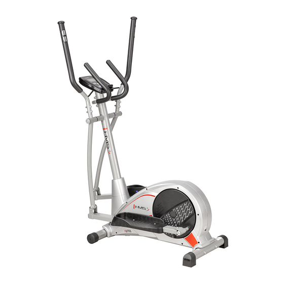
SPECIFICATIONS Weight – 38,5 kg Flywheel – 6 kg Dimensions – 116 x 61 x 160 cm Maximum weight of user – 120 kg MAINTENANCE Your unit has been carefully designed to require minimum maintenance. To ensure this, we recommend that you do the following: keep your unit clean by wiping sweat, dust or other residue off with a soft, clean cloth after each use. -
Page 19: Exploded Drawing
Exploded drawing:... -
Page 20: Parts List
Parts list Q’ty Q’ty Description Description 1 END CAP 48 BEARING 6203 2 HAND PULSE 49 MAGNETIC SET 3 UPPER HANDLEBAR,LEFT 50 LEVERAGED MOTOR 4 HAND PULSE WIRE 51 STEEL BUSHING 5 CONSOLE 52 SENSOR BOX 53 PULLEY φ260 6 HAND PULSE WIRE OF COMPUTER 7 UPPER MOTOR CABLE 54 BELT 8 FRONT HANDLEBAR... - Page 21 41 RIGHT MAIN COVER 88 UPPER HANDLEBAR,RIGHT 42 SCREW ST4 89 LOWER HANDLEBAR,RIGHT 43 REAR STABILIZER 90 RIGHT PEDAL TUBE 44 SCREW ST4 91 RIGHT PEDAL 45 REAR FOOT TUBE 92 RIGHT DISC 46 BOLT M8 47 C-SHAPE BUCKLE Q’ty Q’ty Description Description...
- Page 22 Q’ty Q’ty Description Description Screw M8*P1.25*16L,6 Flat washerФ8.5*Ф28*2T, Flat washer Φ8.2*Φ38*2.5T Wave washerФ17.5*Ф25*0.3T, Wave washerФ19.5*Ф30*0.3T, ScrewM8*P1.25*75L*S20L,6 Semicircle washersФ8*Ф19*2T, Spring washer φ8.5*φ12*1.5T Nylon nut M6*5.5T,10 Wrench 10/13/19 Flat washer Ф6*Ф13*1T Hex wrench 5mm Screw M6*43L*S11L, Hex wrench 6mm...
-
Page 23: Assembly Instruction
Assembly instruction 1.Front stabilizer (73) and rear stabilizer (74) fix on the frame (63). 2.Use screw (46) and washer (22) to tighten. 1. Put the cover into the upright post (20). 1.Connect upper motor cable (7) with lower motor cable (24). - Page 24 1. Insert washer (18) on the upright post (20). 2. Fix the lower handblebar (L/R)(16/89 into the upright post (20). 3. Use screw (13), washer (74), washer (14) to tighten. 1. Loosen screw (25) and washers (12), (74) from pedal tube (26), (90).
- Page 25 Use pre tight screw (11) and washers (74), (22) to fix the front handlebar (8) on the upright post (20). Use pre tight screw (78) and washers (74), (22) to fix on the lower handlebar.
- Page 26 Loosen screw (9) on the computer. Connect upper motor cable (7) and hand pulse wire (4), with the computer (5). Fix the computer (5) into the upright post (20), using screw (9).
-
Page 27: Function Description
COMPUTER FUNCTION SCAN : Alternates between WATTS/CALORIES and RPM/SPEED. 6 seconds per display. RPM : 0~15~999 SPEED : 0.0~99.9 km/h TIME : 0:00~99:59 DISTANCE : 0.00~99.99 km CALORIES : 0~999 MANUAL : 1~16 level PROGRAM : P1~P12 USER : U1~U4 H.R.C : 55%、75%、90%、IND (TARGET) PULSE : P~30~240,max value is available USER DATA : U0 ~U4 (U1 ~ U4 programs set by the user) - Page 28 7. Press MODE to confirm each value setting. WATTS CONSTANT User can default WATTS value at his/her desire 10-350 watts between 10~350 watts by using the UP/ DOWN knob. To fix WATTS constant value and then press ST/STOP key. Use WATTS control mode to train yourself in different WATTS’s constant. Operating process 1.
-
Page 29: Key Functions
5. Set your exercising CALORIES by pressing UP▲/DOWN▼ from 0~990. RANDOM PORGRAM A randomly selected program by the computer that will automatically generate its graph. 1. There are total 16 bars : Every random will result load value of bar. 3. - Page 30 Before programming your training, it is essential to take account of your age, particularly for people of more than 35 years of age, as well as your physical condition. If you have a sedentary lifestyle without regular physical activity, it is vital that you consult your doctor to determine the level of intensity of your training. Once determined, do not attempt to achieve your maximum during the first training sessions.
-
Page 31: Training Instruction
41–905 Bytom serwis@abisal.pl www.abisal.pl www.hms-fitness.pl The equipment label depicting a crossed-out wheeled bin symbol informs that it is forbidden to dispose of waste electrical and electronic equipment together with other types of waste. In accordance with the WEE directive on waste electrical and electronic equipment, separate waste management processes should be applied for this type of equipment. -
Page 32: Bezpečnostní Pokyny
BEZPEČNOSTNÍ POKYNY RADY TÝKAJÍCÍ SE BEZPEČNOSTI Tento výrobek je určen k domácímu i komerčnímu využití a byl navržen tak, aby byla zajištěna maximální bezpečnost. Měly by být dodržovány následující zásady: Před započetím tréninku se poraďte s lékařem za účelem vyloučení překážek ve využívání tohoto cvičebního zařízení. Rozhodnutí lékaře je nezbytné... - Page 33 Schéma:...
-
Page 34: Seznam Dílů
Seznam dílů: Č. Č. Popis Popis 48 Ložisko 6203 Krytka Elektroda snímání tepu 49 Třmen s magnetem Levé madlo 50 Motor regulace zátěže Signální vodič 51 Váleček Počítač 52 Čidlo Spojka signálního vodiče 53 Řemenice φ260 Horní kabel 54 Řemen Pevná... - Page 35 41 Pravý kryt 88 Pravé madlo 42 Šroub ST4 89 Pravá, pohyblivá tyč 43 Vyrovnávací koncovka stabilizátoru 90 Pravá lyžina 44 Šroub ST4 91 Pravý pedál 45 Zadní stabilizátor 92 Pravý talíř 46 Šroub M8 47 Průchodka Č. Č. Popis Popis Levé...
-
Page 37: Postup Montáže
Postup montáže 1. Přední stabilizátor (73) a zadní stabilizátor )74) připevněte k hlavnímu rámu (63). 2. Použijte šrouby (46), podložky (22) a dotáhněte . 1. Na sloupek (20) nasuňte kryt krku (21). 2. Spojte horní kabel (7) se spodním kabelem (24). 3. - Page 38 1. Na osy sloupku (20) nasaďte válečky (18). 2. Na osy sloupku (20) nasuňte spodní pohyblivé tyče (16, 89). 3. Zajistěte šroubem (13) a podložkami (74, 14). 1. Zdemontujte šroub (25) a podložky (12, 74) z lyžiny (26, 90). 2. Lyžinu (26, 90) nasuňte na osu pedálů...
- Page 39 Šrouby (11) a podložky (74, 22) použijte k připevnění pevných madel (8) ke sloupku (20). Šrouby (78) a podložky (74, 22) použijte k připevnění pravého a levého madla (1, 88).
- Page 40 Demontujte šrouby (9) z počítače (5). Horní kabel (7) a signální vodiče (4) spojte s počítačem (5). Počítač (5) připevněte ke sloupku (20) pomocí šroubů (9).
-
Page 41: Popis Funkcí
Počítač Funkce SCAN : V interval 6-ti vteřin se střídavě zobrazuje údaj WATTS/CALORIES (calorie) a RPM/SPEED (rychlost). RPM (otáčky za minutu): 0~15~999 SPEED (rychlost): 0.0~99.9 km/h TIME (čas): 0:00~99:59. DISTANCE (vzdálenost): 0.00~99.99 km CALORIES (calorie): 0~999. SYMBOL SRDCE : bliká MANUAL (manuální... - Page 42 7. Stiskněte klávesu MODE pro potvrzení každé hodnoty. WATTS CONSTANT (program Výkon) Nastavte si konstatntu, kterou trenažér bude během tréninku hlídat v rozmezí 10~350 wattů pomocí kláves UP/ DOWN. Pokud chcete hodnotu upravit stiskněte klávesu START/STOP. Operating process 1. Nastavte hodnotu WATTS pomocí kláves UP▲/DOWN▼ v rozsahu 10-350.. 2.
- Page 43 Po ukončení tréninku si můžete ověřit úroveň své kondice, kdy potvrdíte program RECOVERY a přiložíte dlaně na elektordy pro snímání tepové frekvence. Pokud konzole detekuje tepovku, pak začne odpočítávat 60 sekund a zobrazí výsledek ve formě F1 – F6. F 1 ~ F6 = ÚROVEŃ KONDICE USER DATA (uživatelské...
- Page 44 účelem kontaktujte místo, kde bylo zařízení koupeno nebo místní úřady. Nebezpečné složky obsažené v elektrickém a elektronickém zařízení mohou dlouhodobě negativně působit na životní prostředí a také zdraví lidí. Oddělení péče o klienta: ABISAL Sp. z o.o. ul. Św. Elżbiety 6 41–905 Bytom abisal@abisal.pl www.abisal.pl www.hms-fitness.pl...
- Page 45 Sicherheitsanmerkungen 1. Vor dem ersten Gebrauch sollte die unten stehende Bedienungsanleitung sorgfältig durchgelesen und für die Zukunft aufbewahrt werden. 2. Es sollten alle Warnungen und Vorsichtsmaßnahmen sowie die einzelnen Montageschritte berücksichtigt werden. Nutzen Sie das Gerät nur gemäß seinem Verwendungszweck. 3.
-
Page 46: Wartung
16. Beim Anheben oder beim Transport der Maschine sollte vorsichtig vorgegangen werden, um Schulterverletzungen zu vermeiden. Es sollten entsprechende Anhebe-techniken angewendet oder die Hilfe einer weiteren Person in Anspruch genommen werden. 17. Es dürfen keine Modifikationen am Produkt vorgenommen werden. Bei Bedarf sollte der technische Dienst kontaktiert werden. - Page 47 Detaillierte Zeichnung:...
-
Page 48: Liste Der Teile
Liste der Teile: Beschreibung Meng Beschreibung Meng 1 ENDKAPPE 48 LAGER 6203 2 SENSOR ZUR PULSMESSUNG 49 MAGNET 3 OBERE SCHWINGSTANGE LINKS 50 MOTOR 51 HÜLSE AUS STAHL 4 KABEL SENSORS PULSMESSUNG 5 COMPUTER 52 SENSOREN 53 RIEMENSCHEIBE φ260 6 KABEL SENSORS PULSMESSUNG VOM COMPUTER 7 OBERES MOTORKABEL... - Page 49 81 HÜLSE 21mm 34 GEBOGENE UNTERLEGSCHEIBE 82 SCHLÜSSEL 35 ABDECKUNG DER SCHEIBE 83 SECHSKANTSCHLÜSSEL 5mm 36 SCHEIBE LINKS 84 SECHSKANTSCHLÜSSEL 6mm 37 HALTERUNG 38 FLACHE UNTERLEGSCHEIBE Ф16 85 NETZADAPTER 39 SCHRAUBE ST4 86 KABEL DC 40 HAUPTABDECKUNG LINKS 87 SCHRAUBE 41 HAUPTABDECKUNG RECHTS 88 OBERE SCHWINGSTANGE...
- Page 50 Beschreibung Menge Beschreibung Menge obere Schwingstange rechts 90 Pedalschiene rechts 88 obere Schwingstange links 30 Pedal links Computer 91 Pedal rechts 45 hinterer Standfuß Lenker 16 untere Schwingstange links 63 Rahmen 73 vorderer Standfuß 89 untere Schwingstange rechts 20 Stützstange des Computers 85 Netzadapter 21 Abdeckung des Lenkers Werkzeuge...
- Page 51 flache Unterlegscheibe Ф6*Ф13*1T Sechskantschlüssel 5mm Sechskantschlüssel 6mm Schraube M6*43L*S11L,...
- Page 52 MONTAGEANLEITUNG 1. Befestigen Sie den vorderen Standfuß (73) und den hinteren Standfuß (74) am Hauptrahmen (63). 2. Benutzen Sie dafür Schraube (46) und Unterlegscheibe (22), um alles festzuschrauben.
- Page 53 1. Verbinden Sie das obere Motorkabel (7) mit dem unteren Motorkabel (24) zusammen. 2. Befestigen Sie die Stützstange des Computers (20) und die mittlere Abdeckung (21) am Rahmen mittels Schraube (23), Unterlegscheibe (74) und Unterlegscheibe (22). 1. Bringen Sie die Unterlegscheibe (18) auf die Stützstange des Computers (20) an.
- Page 54 1. Lösen Sie Schraube (25), Unterlegscheibe (12) und Unterlegscheibe (74). 2. Benutzen Sie Schraube (25), Unterlegscheibe (12), Unterlegscheibe (74) und Schraube (13), um den vorderen Teil zu befestigen. 3. Benutzen Sie Schraube (13), Unterlegscheibe (74), Unterlegscheibe (31) und Schraube (34), um den hinteren Teil zu befestigen.
- Page 55 Benutzen Sie Schraube (78), Unterlegscheibe (74) und Unterlegscheibe (22), um die Schwingstangen zu befestigen. Lösen Sie die Schraube beim Computer (9). Verbinden Sie das obere Motorkabel und das Kabel des Sensors zur Pulsmessung mit dem Kabel des Computers mittels Schraube (9) zusammen.
- Page 57 Computer FUNKTIONEN SCAN: Abwechselnd zwischen WATTS/CALORIES (Kalorienverbrauch) und RPM/SPEED (Geschwindigkeit). Die Zeit wird 6 Sekunden lang angezeigt. UMDREHUNGEN PRO MINUTE / RPM : 0~15~999 GESCHWINDIGKEIT / SPEED : 0.0~99.9 km/h ZEIT / TIME : 0:00~99:59. DISTANZ / DISTANCE : 0.00~99.99 km KALORIENVERBRAUCH / CALORIES : 0~999.
- Page 58 4. Bestimmen Sie den Zielwert vom PULS (HERZFREQUENZ) / PULSE (HEART RATE) mittels der Taste UP▲/DOWN▼ im Bereich P~30~240. 5. Drücken Sie MODE, um alle Einstellungen zu bestätigen. 6. Wenn Sie keine Trainingsparameter wie ZEIT (TIME) / DISTANZ (DISTANCE) / KALORIENVERBRAUCH (CALORIES) / PULS (PULSE) einstellen wollen, drücken Sie die Taste START/STOP START/STOP), um sofort das Training zu beginnen.
- Page 59 BENUTZER (USER) - Gestalten Sie ein eigenes Profil des Programms mittels U1~U4 und bestimmen Sie den Widerstand für alle Stufen. Dann wird das Programm automatisch gespeichert und man kann es in der Zukunft verwenden. U0 kann genauso eingestellt werden wie U1~U4, aber dieses Programm kann nicht gespeichert werden. 1.
-
Page 60: Funktionen Der Tasten
RANDOM-PROGRAMM – Das zufällig vom Computer ausgewählte Programm, das automatisch sein Diagramm generiert. 1. Es gibt insgesamt 16 Blöcke: Jedes Random-Programm bestimmt den Wert des Blocks. 2.. Nach dem Drücken der Taste START kann der Benutzer mittels der Taste UP▲ / DOWN▼ den Wert jedes Blocks bestimmen. - Page 61 1. MODE: Diese Taste dient zur Auswahl der Funktionen und zur Bestätigung der eingeführten Einstellungen. 2. UP▲/DOWN▼: Diese Taste dient zur Erhöhung und Verringerung sowie zur Auswahl der Optionen. 3. START/STOP: Diese Taste dient zum EINSCHALTEN / AUSSCHALTEN. 4. RECOVERY: Das ist ein Test zur Messung der Herzfrequenz.
- Page 62 Die Kennzeichnung von Geräten mit einem durchgestrichenen Abfallbehälter weist darauf hin, dass das Produkt vom normalen Haushaltsabfall getrennt gesammelt und entsorgt werden muss. Nach der WEEE-Richtlinie über Elektro- und Elektronik-Altgeräte muss man diese Art der Geräte getrennt entsorgen. Der Nutzer, der dieses Gerät entsorgen will, ist dazu verpflichtet, es an die Sammelstelle für Elektro- und Elektronik-Altgeräte zurückzugeben, was zur Wiederverwendung, zum Recycling oder zur Verwertung und damit zum Schutz der Umwelt beiträgt.
-
Page 63: Karta Gwarancyjna
KARTA GWARANCYJNA Nazwaa artykułu: ......................Kod EAN: ........................Data sprzedaży: ......................WARUNKI GWARANCJI Sprzedawca w imieniu Gwaranta udziela gwarancji na terytorium RP na okres 24 miesięcy od daty sprzedaży. Gwarancja będzie respektowana przez sklep lub serwis po przedstawieniu przez klienta: - czytelnie i poprawnie wypełnionej karty gwarancyjnej z pieczątką... -
Page 64: Guarantee Card
GUARANTEE CARD Article name: …………………………………………………………………………. EAN code: ……………………………………………………………………………… Date of sale: ………………………………………………………………………….. GUARANTEE TERMS The Seller provides guarantee on behalf of the Guarantor within the territory of the Republic of Poland for the period of 24 months from the date of sale. The Guarantee will be recognised by the shop or service centre after the client provides: - clearly and correctly filled-in guarantee card with the sale stamp and the seller’s signature - valid purchase confirmation for the equipment... - Page 65 The guarantee for sold goods is not exclusive, does not limit or suspend entitlements of the buyer resulting from the non-compliance of the product with the agreement. Notes on the course of repairs Item Date of Date of Course of repairs Signature of the recipient notificacion provision...
-
Page 66: Záruční List
ZÁRUČNÍ LIST Název produktu: …………………………………………………………………………………………….. EAN kod: ……………………………………………………………………………………………. Datum prodeje: ……………………………………………………………………………………………… ZÁRUČNÍ PODMÍNKY Prodávající jménem Ručitele poskytuje záruku na území Polska po dobu 24 měsíců od data prodeje. Záruka bude respektována obchodem nebo servisem po předložení zákazníkem: čitelně a správně vyplněného záručního listu s razítkem a podpisem prodávajícího platného doklad o koupi produktu s datem prodeje (účtu) reklamovaného produktu Jakékoli závady a poškození... - Page 67 ěn ě Upozorn í o oprav Č. Datum vydání Průběh oprav Podpis příjemce (obchod, majitel) Datum nahlášení...
- Page 68 GARANTIEKARTE Artikelname: EAN-Code: Verkaufsdatum: GARANTIEBEDINGUNGE 1. Der Verkäufer gewährt im Namen des Garanten eine Garantie für 24 Monate nach dem Verkaufsdatum auf dem Hoheitsgebiet der Republik Polen. 2. Die Garantie wird von dem Laden oder dem Service nach Vorlage: der leserlich und korrekt ausgefüllten Garantiekarte mit Verkaufsstempel und Unterschrift des Verkäufers eines gültigen Kaufnachweises für das Gerät mit dem Verkaufsdatum / Rechnung/ der beanstandeten Ware durch den Kunden respektiert...
- Page 69 Die Garantie für die verkaufte Ware schließt die Rechte des Käufers aus der Nichtübereinstimmung der Ware mit dem Vertrag nicht aus, schränkt sie nicht ein und setzt sie nicht aus. DAS GERÄT IST NICHT ZUR VERWENDUNG ZUR REHABILITATION UND THERAPEUTISCHEN ZWECKEN BESTIMMT VERMERKE ÜBER DEN VERLAUF DER REPARATUREN Lfd.
- Page 70 IMPORTER: ABISAL SP. .Z.O.O., ul. Świętej Elżbiety 6, 41-905 Bytom Service: Pyskowicka 14, 41- 807 Zabrze abisal@abisal.pl www.abisal.pl...
Need help?
Do you have a question about the H6996 and is the answer not in the manual?
Questions and answers