
Related Manuals for Campbell CR10X


Summary of Contents for Campbell CR10X
- Page 1 CR10X Measurement Control Module Instruction Manual Issued 1.3.02 (rev. 30.9.05) Copyright 2002 Campbell Scientific, Inc. Copied under licence by Campbell Scientific Ltd.
- Page 3 Note that goods sent air freight are subject to Customs clearance fees which Campbell Scientific will charge to customers. In many cases, these charges are greater than the cost of the repair. Campbell Scientific Ltd,...
-
Page 5: Table Of Contents
CR10XM Modules only................ix Part I Overview OV1. Physical Description ..............OV-1 OV1.1 Wiring Panel — Model CR10WP .........OV-2 OV1.2 Connecting Power to the CR10X ..........OV-5 OV2. Memory and Programming Concepts ..........OV-6 OV2.1 Internal Memory..............OV-6 OV2.2 CR10X Instruction Types............OV-8 OV2.3 Program Tables, Execution Interval and Output Intervals ..OV-8 OV3. - Page 6 1.5 Memory Allocation — *A Mode ............1-8 1.5.1 Internal Memory ................. 1-8 1.5.2 *A Mode ................... 1-10 1.5.3 Allocation of Final Storage Area 2 when using the CR10X with Extended Memory Options..........1.12 1.6 Memory Testing and System Status — *B Mode ......1-12 1.7 *C Mode —...
- Page 7 Section 5. Telecommunications .........5-1 5.1 Telecommunications Commands............5-2 5.2 Remote Programming of the CR10X............ 5-5 Section 6. 9-Pin Serial Input / Output......6-1 6.1 Enabling and Addressing Peripherals ........... 6-2 6.1.1 Pin-Enabled Peripherals............... 6-2 6.1.2 Addressed Peripherals..............6-3 6.2 Ring Interrupts ..................6-3 6.3 Interrupts During Data Transfer ............
- Page 8 13.3.1 The Input Settling Time Constant........... 13-4 13.3.2 Effect of Lead Length on Signal Rise Time ......13-7 13.3.3 Transients Induced by Switched Excitation......13-8 13.3.4 Summary of Settling Errors for Campbell Scientific Resistive Sensors..............13-10 13.4 Thermocouple Measurements............13-13 13.4.1 Error Analysis ...............
- Page 9 B.3.4 Configuration 4 ................B-7 B.3.5 Configuration 5 ................B-8 B.4 Program Examples ................B-8 B.4.1 Example 1: Atmospheric Research AIR-DB-1A Barometer ..B-8 B.4.1.1 CR10X / Barometer Configuration Limitations ....B-8 B.4.1.2 CR10X / Barometer Connection ..........B-9 B.4.1.3 Instruction15 Parameter Considerations......B-10 B.4.1.4 Barometer Program ............B-11 B.4.2 Example 2: CR10X to CR10X Communication.......B-13...
- Page 10 H.2.2.2 Programming Example: Calling CR10X using RF Modems ................H-4 H.3 Remote Datalogger Programming ............H-4 H.3.1 Program Example for a Remote 21X .........H-5 Appendix I. Modbus on the CR10 and CR10X ....I-1 I.1 Terminology ................... I-1 I.2 Communications and Compatibility............I-1 I.2.1 RF Communications ..............I-2 I.2.2 CR10/10X to CR10/10X Communication........
-
Page 11: Selected Operating Details
98765 for the number of bytes left in Program Memory (see Section 1). Password/Program changes during power-up – When primary power is applied to the CR10X, it tests the Flash memory and loads the current program into RAM (see page vii and Section OV.5). If the ring line on the 9-pin connector is raised during this memory test, there will be a 128 second delay before the program is compiled and run. -
Page 12: Cautionary Notes
Connecting these leads in the reverse order creates the possibility of a short circuit (see Section 14). Voltages in excess of 5.6V applied to a control port can cause the CR10X to malfunction and damage the CR10WP wiring panel. Voltage pulses can be counted by the CR10X pulse counters configured for high frequency pulses. -
Page 13: Cr10Xm Modules Only
CR10XM as a component comply with European EMC legislation. Compliance of the CR10X with the European directives on EMC is reliant on its use with the wiring panel supplied by Campbell Scientific (see page OV-2 of this manual). -
Page 15: Part I Overview
Section 13 describes CR10X measurement procedures in detail. The Prompt Sheet is an abbreviated description of the programming instructions. Once familiar with the CR10X, it is possible to program it using only the Prompt Sheet as a reference, consulting the manual if further detail is needed. -
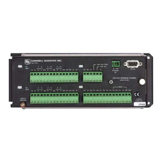
Page 16: Ov1.1 Wiring Panel - Model Cr10Wp
D-type connectors located at the end of the module. – The power supply is external to the CR10X. This gives you a wide range of options for powering the CR10X (see Section 14). OV1.1 Wiring Panel — Model CR10WP The CR10WP Wiring Panel and CR10X datalogger make electrical contact through the two D-type connectors at the (left) end of the CR10X. -
Page 17: Cr10X Wiring Panel And Programming Instructions
28 Wire Meas 29 INW Press 4X Set port x high 5X Set port x low 6X Toggle port x 7X Pulse port x 96 Port Subr. 97 Port Subr. 98 Port Subr. Figure OV-2 CR10X Wiring Panel and Programming Instructions OV-3... - Page 18 H input is measured with respect to the voltage on the L input. When making single-ended measurements, either the H or L input may be used as an independent channel to measure voltage with respect to the CR10X analogue ground (AG). The single-ended channels are numbered sequentially starting with 1H;...
-
Page 19: Ov1.2 Connecting Power To The Cr10X
The actual output voltage of the switched supply is 0.5V below that of the CR10X supply voltage. This can be used to power sensors or devices requiring an unregulated 12 volts. The output is limited to 600mA current. -
Page 20: Ov2. Memory And Programming Concepts
(see Section 14). OV2. Memory and Programming Concepts The CR10X must be programmed before it will make any measurements. A pro- gram consists of a group of instructions entered into a program table. The program table is given an execution interval which determines how frequently that table is executed. - Page 21 The Operating System is loaded into Operating System (4096 Bytes) Flash Memory at the factory. System (96 Kbytes) Memory is used while the CR10X is running calculations, buffering data and Active Program for general operating tasks. (default 2048 bytes) Any time a user loads a program into...
-
Page 22: Ov2.2 Cr10X Instruction Types
CR10X Instruction Manual OV2.2 CR10X Instruction Types Figure OV-4 illustrates the use of three different instruction types which act on data. The fourth type, Program Control, is used to control output times and to vary program execution by using techniques such as loops or conditional tests. - Page 23 Part 1. Overview INPUT/OUTPUT INSTRUCTIONS Specify the conversion of a sensor signal SENSORS to a data value and store it in Input Storage. Programmable entries specify: (1) the measurement type (2) the number of channels to measure (3) the input voltage range (4) the Input Storage Location CONTROL (5) the sensor calibration constants...
-
Page 24: Ov3. Communicating With The Cr10X
CR10X. This may be either Campbell Scientific’s portable CR10KD Keyboard/Display or a computer/terminal. The CR10KD is powered by the CR10X and connects directly to the serial port via the SC12 cable (supplied with the CR10KD). No interfacing software is required. -
Page 25: Ov3.1 Cr10X Keyboard / Display
Part 1. Overview To communicate with any device other than the CR10KD, the CR10X enters its Telecommunications Mode and responds only to valid telecommunications commands. Within the Telecommunications Mode, there are two ‘states’; the Telecommunications Command State and the Remote Keyboard State. Commu- nication is established in the Telecommunications Command State. -
Page 26: Ov3.3 Ascii Terminal Or Computer With Terminal Emulator
Most computer/terminal devices need RS232 input logic levels of -5V for logic low and +5V for logic high. Logic levels from the CR10X’s serial I/O port are 0V for logic low and +5V for logic high. The SC32A converts and optically isolates the voltages passing between the CR10X and the external terminal device. -
Page 27: Ov4. Programming The Cr10X
Part 1. Overview Once the computer is functioning as a terminal, initiate communications by sending the CR10X several carriage returns for the CR10X to match the baud rate and respond with ‘*’. Enter the 7H command to enter the Remote Keyboard State. -
Page 28: Ov4.3 Programming Sequence
(then ) Back up to the start of current array RETURN When using a computer/terminal to communicate with the CR10X there are some keys available in addition to those found on the CR10KD. Table OV-3 lists these keys. Table OV-3 Additional Keys Allowed in Telecommunications... -
Page 29: Ov4.4 Instruction Format
OV4.4 Instruction Format Instructions are identified by an instruction number. Each instruction has a num- ber of parameters that give the CR10X the information it needs to execute the instruction. The CR10X Prompt Sheet has the instruction numbers in red, with the parameters briefly listed in columns following the description. -
Page 30: Ov5. Programming Examples
PC208W) SMCOM or CSMCOM. Using the *D Mode to save or load a program from a Storage Module is described in Section 1. Once a program is loaded into the CR10X it will be stored in flash memory and will be automatically loaded and executed when the datalogger is powered up. -
Page 31: Ov5.1 Sample Program 1 (Direct Programming
(i.e. while ‘HELLO’ is displayed on the CR10KD). Before we enter a programming example we will ensure that there is no active program in the CR10X by loading an ‘empty’ program using the *D mode: Press these Display will show... - Page 32 Enter 10 and advance to third program instruction. 03:P70 The SAMPLE instruction. This directs the CR10X to take a reading from an Input Storage location and send it to Final Storage (an Output Processing Instruction). 01:0000 Enter 70 and advance to the first parameter (repetitions).
-
Page 33: Ov5.2 Sample Program 1 (Using Edlog
Part 1. Overview The CR10X is now programmed to measure the internal temperature every five seconds and send each reading to Final Storage. Values in Final Storage can be viewed using the *7 Mode. Press these Display will show Explanation of this... - Page 34 (TC) temperature measurement, the temperature of the reference junction (in this example, the approximate panel temperature) must be measured. The CR10X takes the reference temperature, converts it to the equivalent TC volt- age relative to 0 C, adds the measured TC voltage, and converts the sum to temperature through a polynomial fit to the TC output curve (see Section 13 for more information on thermocouple measurements).
- Page 35 03:10 Set Output Flag 0 The CR10X is programmed to measure the thermocouple temperature every sixty seconds. The If Time instruction sets the Output Flag at the beginning of every hour. Next, the Output Instructions for time and average are added.
- Page 36 CR10X Instruction Manual the Output Flag high every hour. The additional Output Instructions which will now be entered do not produce output every hour because they are preceded by another Instruction 92 which sets the Output Flag high at midnight (and sets it low at any other time).
-
Page 37: Ov5.4 Sample Program 2 (Using Edlog
Part 1. Overview 05:0021 Enter and advance to location for hours and minutes (24hr time) 1324 05:1324 Key in hrs.:min. (1:24 PM in this example). :13:24:01 Clock set and running. LOG 1 Exit *5 Mode, compile Table 1, start logging data. OV5.4 Sample Program 2 (Using Edlog) The following shows Sample Program 2 as it would be programmed using Edlog: *Table 1 Program... -
Page 38: Ov5.5 Editing An Existing Program
SM192/SM176/CSM1 OV5.5 Editing an Existing Program When you edit an existing program in the CR10X, entering a new instruction inserts the instruction; entering a new parameter value replaces the previous value. To insert an instruction, enter the program table and advance to the position where the instruction is to be inserted (i.e. - Page 39 Part 1. Overview Table OV-4 lists the instructions used with the various methods of data retrieval. Table OV-4 Data Retrieval Methods and Related Instructions Method Instruction/Mode Section in Manual Storage Module Instruction 96 4.1, 12 ∗8 ∗9 Telecommunications Telecommunications Commands Instruction 97 Instruction 99 Printer or other...
- Page 40 The DSP4 Heads up Display allows you to view data in Input Storage. Also buffers Final Storage data and writes it to printer or Storage Module. All Campbell Scientific RS232 interfaces have a female 25-pin RS232 connector, with the exception of the SC929, which plugs directly into a 9-way DTE ‘D’...
-
Page 41: Ov7. Specifications
Up to ten SDI-12 sensors can be connected to each selectable for any channel. The resolution for differential port. measurements is better than that for single-ended *AC voltage: must be centred around CR10X ground. measurements because two measurements are 10TCRT THERMOCOUPLE REFERENCE REFERENCE ACCURACY: ±(0.01% of reading + averaged together. -
Page 43: Part Ii User Guide
The ∗4 Table is only available when a special program created by Edlog is loaded in the CR10X. When a program table is first entered the display shows the table number in the ID field and 00 in the data field. -
Page 44: Subroutines
If the execution interval for a table is less than the time required to process that table, the CR10X finishes processing the table and waits for the next occurrence of the execution interval before again initiating the table (i.e. when the execution interval has elapsed and the table is still executing, that execution is skipped). -
Page 45: Parameter Entry Table
1.1.4 *4 Parameter Entry Table The CR10X *4 Mode is an option that allows inexperienced personnel to change parameters (such as sensor calibrations) in a datalogger program without having to understand or have access to the program. The *4 function is normally used in applications where the datalogger is pre-programmed, but where site-specific parameters still have to be entered at the time of installation. - Page 46 If the ∗4 feature is enabled in Edlog when printing a program to a printer or disk file, the ∗4 list is printed at the end of the file. Once the Edlog-created program has been sent to the CR10X, it can be saved in the Flash memory program storage area using the ∗D Mode (Section 1.8).
-
Page 47: Compiling A Program
− Security is blocking access to ∗4. 1.1.5 Compiling a Program When a program is first loaded into the CR10X, or if any changes are made in the *1, *2, *3, *4, *A or *C Modes, the program must be compiled before it will run. -
Page 48: Displaying And Altering Input Storage, Flags And Ports - *6 Mode
CR10X User Guide To set the year, day or time, enter the *5 Mode and advance to display the appropriate value. Key in the desired number and enter the value by pressing When a new value for hours and minutes is entered, the seconds are set to zero and the current time is again displayed. -
Page 49: Displaying And Toggling User Flags
To preserve these values, always compile in the *6 Mode after altering the program tables. 1.3.2 Displaying and Toggling User Flags If you press while the CR10X is displaying a location value, the current status of the user flags is displayed in the following format: ‘ ’. The digits 00:010010 represent the flags;... -
Page 50: Compiling And Logging Data - *0 Mode
*0 Mode. The same is true when the programs are compiled with *B or *D. To minimise current drain, the CR10X should be left in the *0 Mode when logging data. 1.5 Memory Allocation — *A Mode 1.5.1 Internal Memory... -
Page 51: Memory Allocation In The Cr10X
Operating System The Operating System is loaded into (4096 Bytes) (96 Kbytes) Flash Memory at the factory. System Memory is used while the CR10X is Active Program running calculations, buffering data and (default 2048 bytes) for general operating tasks. Any time a user loads a program into... -
Page 52: A Mode
0, maximum limited by available memory and constraints on Input and Final Storage). Entering 0 will cause the CR10X to assign the exact number needed, and will also result in the CR10X erasing all data whenever the program is changed and re-compiled. - Page 53 CR10X-1M and ten minutes for a CR10X-2M. Please be patient while the reset takes place. If the CR10X is turned off in the middle of a reset, it will perform the reset the next time it is powered up.
-
Page 54: Allocation Of Final Storage Area 2 When Using The Cr10X
RAM, the CR10X then allocates some of the flash memory as well. • If flash memory is required, the CR10X may have to adjust the size of FS2 to force the division between Areas 1 and 2 to align with the nearest flash page. -
Page 55: C Mode - Security
The *C Mode (see Table 1-6) is used to block access to your program information and certain CR10X functions. There are three levels of security, each with its own 4-digit password. Setting a password to a non-zero value ‘locks’ the functions secured at that level. -
Page 56: D Mode - Save Or Load Program
(i.e. the information for the *1, *2, *3, *4, *A, *C and *B Modes). Several programs can be stored in the CR10X flash memory and later recalled and run using the *D Mode or Instruction 111. -
Page 57: Internal Flash Program Storage
Set Full/Half Duplex Set Power-up Options If the CR10X program has not been compiled when the command to save a pro- gram (i.e. command 1, 2 or 7) is entered, it will be compiled before the program is saved. When a program is loaded, it is immediately compiled and run. After a command is executed, ‘... -
Page 58: Program Transfer With Storage Module
1.8.2 Program Transfer with Storage Module The Storage Module and Keyboard/Display or computer must both be connected to the CR10X. Enter *D7N, where N is the Storage Module address. Address 1 will work with any Storage Module address, because the CR10X searches for the Storage Module with the lowest address that is connected. -
Page 59: Full/Half Duplex
The CR10X can be programmed on power-up using a Storage Module. Storage Modules can store up to eight separate programs. If a program is stored as pro- gram number 8, and if the Storage Module is connected to the CR10X at power- up, program number 8 is downloaded, compiled and run. -
Page 60: Setting Power-Up Options
CR10X User Guide 1.8.5 Setting Power-up Options Setting options for the program on power-up allows you to specify what information to retain from the time when the datalogger was last switched on. This allows Flag/Port status, the User Timer and the Input/Intermediate Storage to be cleared or not cleared. -
Page 61: Section 2. Internal Data Storage
Section 2. Internal Data Storage Final Storage is the portion of memory where the CR10X stores final processed data. It is from Final Storage that data is transferred to your computer or external storage peripheral. 2.1 Final Storage Areas, Output Arrays and Memory Pointers The size of Final Storage is expressed in terms of memory locations or bytes. - Page 62 CR10X User Guide The Data Storage Pointer (DSP) is used to determine where to store each new data point in the Final Storage area. The DSP advances to the next available memory location after each new data point is stored.
-
Page 63: Data Output Format And Range Limits
SPTR to the new DSP location. It saves the data until the Storage Module is connected. Then, during the next execution of Instruction 96, the CR10X outputs all of the data between the SPTR and the DSP and updates the SPTR to the DSP location (see Section 4.) The SPTR can also be positioned via the keyboard for manually initiated data transfer to the Storage Module (*8 Mode). -
Page 64: Input And Intermediate Storage Data Format
2.2.2 Input and Intermediate Storage Data Format While output data has the limits described above, the computations performed in the CR10X are done in floating point arithmetic. In Input and Intermediate Storage, the numbers are stored and processed in a binary format with a 23-bit binary mantissa and a 6-bit binary exponent. -
Page 65: Cr10X With Extended Flash Memory
Exit *7 Mode 2.4 CR10X with Extended Flash Memory Final storage with Extended Flash memory (e.g. in the CR10X-1M) works on a ‘ring’ method of data storage – when the storage area becomes full, blocks of memory are erased at the start position in anticipation of new data being read, and the oldest data areas are then overwritten. -
Page 67: Section 3. Instruction Set Basics
(FP), 4-digit integers (4) and 2-digit integers (2). The parameter data type is identified in the listings of the instruction parameters in Sections 9-12. Different data types are used to allow the CR10X to make the most efficient use of its memory. -
Page 68: Entering Negative Numbers
CR10X User Guide 3.3 Entering Negative Numbers After entering a number, press ‘-’ (if using a computer) or to change the num- ber’s sign. On floating point numbers a minus sign (-) will appear to the left of the number. Excitation voltages in millivolts for I/O Instructions are 4-digit integers;... -
Page 69: Output Processing
Instruction (see Sections 11 and 12). 3.7 Use Of Flags: Output and Program Control There are 10 flags which may be used in CR10X programs. Two of the flags are dedicated to specific functions: flag 0 causes Output Processing Instructions to write to Final Storage, and flag 9 disables intermediate processing (see ‘Output... -
Page 70: The Output Flag
CR10X User Guide Table 3-2 Flag Description Flag 0 – Output Flag Flag 1 to 8 – User Flags Flag 9 – Intermediate Processing Disable Flag Flags are set with Program Control Instructions. The Output Flag (flag 0) and the intermediate programming disable flag (flag 9) are always set low if the set high condition fails. -
Page 71: User Flags
Section 3. Instruction Set Basics Table 3-3 Example of the Use of Flag 9 Inst. Param. Loc. Entry Description If wind speed < 4.5m/s Wind speed location Comparison: < Minimum wind speed for histogram Set Flag 9 high Histogram Enter histogram parameters here Set Flag 9 Low NOTE Flag 9 is automatically reset in the same way as flag 0. -
Page 72: If Then / Else Comparisons
CR10X User Guide 3.8.1 If Then / Else Comparisons Program Control Instructions can be used for ‘If then/else’ comparisons. When Command 30 (Then do) is used with Instructions 83 or 88-92, the If instruction is followed immediately by instructions to execute if the comparison is true. The Else instruction (Instruction 94) is optional and is followed by the instructions to execute if the comparison is false. -
Page 73: Nesting
Section 3. Instruction Set Basics A logical OR construction is also possible. Figure 3-3 illustrates an instruction sequence that results in subroutine X being executed if either A or B is true. IF A (88-92 with command 30) Call subroutine X (86, command=X) ELSE (94) IF B (88-92 with command 30) Call subroutine X (86, command=X) -
Page 74: Input/Output Instruction Memory And Execution Times
CR10X User Guide Table 3-5 Input/Output Instruction Memory and Execution Times INPUT PROG. EXECUTION TIME (ms) INSTRUCTION LOC. BYTES MEASUREMENT RANGE Code 0 1-4 or NA Code 10 11-14 Code 20 21-24 Code 30 31-34 VOLT (SE) 3.0 + 40.2 * R 4.6 + 5.2R... -
Page 75: Processing Instruction Memory And Execution Times
Section 3. Instruction Set Basics When attempting to make a fast series of measurements and calculations, it is important to examine the time required for the automatic calibration sequence and possibly make use of the program-controlled calibration, Instruction 24. Section 13 describes the calibration process. -
Page 76: Program Control Instruction Memory And Execution Times
CR10X User Guide Table 3-7 Output Instruction Memory and Execution Times (R = No. of Repetitions) Instruction Memory Execution Time (ms) Inter. Final Prog. Flag 0 Low Flag 0 High Loc. Values Bytes 69 WIND VECTOR 2+9R (2, 3 or 4)R 4.0 + 17.4R 3.3 + 70.7R... -
Page 77: Error Codes
9 – see Section 1) counts the number of times the voltage drops below 9.6 volts and displays a double dash (--) if the CR10X is currently in a low voltage shut down state. Below approximately 8.5V the CR10X will not communicate with the CR10KD or modem, although there may be enough power to display characters on the CR10KD. - Page 78 Editor Program Table full Compile Intermediate Storage full Compile Storage Area 2 not allocated Run Time CR10X reset by watchdog timer Run Time Insufficient Input Storage Run Time Low battery voltage Editor Attempt to allocate more Input or Intermediate Storage than is available...
-
Page 79: Section 4. External Storage Peripherals
External data storage devices are used to provide a data transfer medium you can carry from the test site to the lab and to supplement the internal storage capacity of the CR10X, allowing longer periods between visits to the site. The standard data storage peripheral for the CR10X is the Storage Module. -
Page 80: Output Device Codes For Instruction 96 And *8 Mode
To the other Final Storage Area [Inst. 96 only], entire active Final Storage Area If the CR10X is using the 9-pin connector for other I/O tasks when Instruction 96 is executed, the output request is put in a queue and program execution continues. -
Page 81: Output To Storage Module
. 1 is a universal address which will find the Storage Module with the lowest number address that is connected. If a Storage Module is not connected, the CR10X will not advance the SPTR and the Storage Module drops out of the queue until the next time Instruction 96 is executed. -
Page 82: Use Of Storage Modules (Sm192/716 And Csm1)
((20 x 24) + 11). 62280 divided by 491 = 126.8 days. Therefore, the CR10X would have to be visited every 126 days to retrieve data, because write-over would begin on the 127th day. Note that it is recommended that the site is visited more frequently than this for routine maintenance, and so the data storage capacity would not be a factor in this instance. -
Page 83: Storage Module Addressing
(Instruction 96), Different data to be output to different Modules, and Transfer of data from a Module that is left with the CR10X to a Module that is hand carried to the site for data transfer (*9 Mode). -
Page 84: Mode Data Dump To Storage Module
CR10X User Guide To be certain that the SM has been connected to the CR10X during an execution of Instruction 96, you can: • leave the SM connected for a time longer than an execution interval • use the SC90 9-Pin Serial Line Monitor. The SC90 contains an LED which lights up during data transmission. - Page 85 Section 4. External Storage Peripherals Table 4-3 *9 Mode Commands for SM192/716 Storage Module Command Display Description 01: 0000 RESET: enter 248 to erase all data and programs. While erasing, the SM checks memory. 01: XX The number of good chips is then displayed (six for SM192, 22 for SM716).
-
Page 86: Printer Output Formats
NOTE You must specifically program the CR10X to output the date and time values. The Output Array ID, Day and Time are always 4-character numbers, even when high resolution output is specified. -
Page 87: Comma Delineated Ascii
Section 4. External Storage Peripherals Each full line of data contains eight data points (79 characters including spaces), plus a carriage return (CR) and line feed (LF). If the last data point in a full line is high resolution, it is followed immediately with a CR and LF. If it is low reso- lution, the line is terminated with a space, CR and LF. -
Page 89: Section 5. Telecommunications
Telecommunications is used to retrieve data from Final Storage directly to a computer and to program the CR10X. Whenever you use a computer or terminal instead of the CR10KD to communicate with the CR10X you are using telecommunications. -
Page 90: Telecommunications Commands
Several carriage returns (CR) must be sent to Commands that return Campbell Scientific the CR10X to allow it to set its baud rate to that binary format data (i.e. the F and K of the modem/terminal (300, 1200, 9600). Once... - Page 91 [loc. no.]I DISPLAY/CHANGE INPUT STORAGE - CR10X sends the value stored at the location. A new value and CR may then be sent. CR10X sends checksum. If no new value is sent (CR only) the location value remains the same.
- Page 92 SECTION 5. TELECOMMUNICATIONS CURRENT INFORMATION - In response to the K command, the CR10X sends datalogger time, user flag status, the data at the input locations requested in the J command, and Final Storage Data if requested by the J command. Used in the Monitor Mode and with Heads Up Display.
- Page 93 SECTION 5. TELECOMMUNICATIONS nnnnU RETURN VALUE - Returns V[value] C[checksum] where nnnn refers to an input location, port, or flag, V is the value at the input location, port or flag, and C is the checksum. For nnnn = 90ff, then nnnn refers to flag ff. For nnnn = 91pp, then nnnn refers to port pp.
-
Page 94: Remote Programming Of The Cr10X
Entering *0 exits the Remote sending a CR, line feed (LF), and the prompt ’>’. Keyboard State and returns the datalogger to the The CR10X is then ready to receive the standard Telecommunications Command State, awaiting keyboard commands; it recognises all the another command. -
Page 95: Section 6. 9-Pin Serial Input / Output
Section 6. 9-Pin Serial Input / Output All external communication peripherals connect to the CR10X through the 9-pin subminiature D-type socket connector located on the front of the Wiring Panel (see Figure 6-1). Table 6-1 shows the I/O pin configuration and gives a brief description of the function of each pin. -
Page 96: Enabling And Addressing Peripherals
CR10X has only one transmit line (pin 9) and one receive line (pin 4). The CR10X selects a peripheral in one of two ways: 1) A specific pin is dedicated to that peripheral and the peripheral is enabled when the pin goes high; this is referred to as pin-enabled or simply enabled. -
Page 97: Addressed Peripherals
Ring line through a process of elimination (see Figure 6-3). The CR10X raises the CLK/HS line forcing all SDs to drop the Ring line. If the Ring line is still high the peripheral is a modem, and the ME line is raised. -
Page 98: Interrupts During Data Transfer
When a modem raises the Ring line, the CR10X responds by raising the ME line. The CR10X must then receive carriage returns until it can establish the baud rate. When the baud rate has been set, the CR10X sends a carriage return, line feed, and ‘*’. -
Page 99: Synchronous Device Communication
SDs differ from enabled peripherals in that they are not enabled solely by a hardware line. An SD is enabled by an address synchronously clocked from the CR10X. Up to 16 SDs may be addressed by the CR10X, requiring only three pins of the 9-pin connector. -
Page 100: Synchronous Device Addresses
The SD addressed by State 2 enters State 3. All other SDs enter State 4. An active SD returns to State 1 by resetting itself, or by the CR10X forcing it to reset. Active SDs have different acknowledgement and communication protocols. Once addressed, the SD is free to use the CLK/HS, TXD and RXD lines according to its protocol with the CR10X. -
Page 101: Modem / Terminal And Computer Requirements
State 5 is a branch from State 1 when the SDE line is high and the CLK/HS line is low. The SDs must drop the Ring line in this state. This state is not used by SDs. The CR10X must force the SDs back to the reset state from State 5 before addressing SDs. -
Page 102: Communication Protocol And Trouble Shooting
CR10X User Guide is taken from these pins. For equipment configured as DTE (see Table 6-3) a direct ribbon cable connects the computer/terminal to the SC32A. Clear to Send (CTS) pin 5, Data Set Ready (DSR) pin 6, and Received Line Signal Detect... - Page 103 1’s. When parity checking is used, the eighth bit is set to either a 1 or a 0 to make the parity of the character correct. The CR10X ignores the eighth bit of a character that is received, and transmits the eighth bit as a binary 0. This method is generally described as ‘no parity’.
- Page 104 If the CR10X is connected to the SC32A RS232 interface and a modem/terminal, and ‘*’ is not received after sending carriage returns: Verify that the CR10X has power at the 12V and ground inputs, and that the cables connecting the devices are securely connected.
-
Page 105: Section 7. Measurement Programming Examples
Input Storage locations used to store the data. It is unlikely that an application and CR10X configuration would exactly duplicate that assumed in an example. Also, the format of your own program listing may vary slightly from those shown, depending on which version of Campbell Scientific Datalogger Support Software you are using. -
Page 106: Wiring Diagram For 50Y
CR10X User Guide 7-1. A short jumper wire is connected between Control Port 1 and the Switched 12V Control. CAUTION The Switched 12V Control terminal will be permanently damaged if 12V is applied to it. Never connect 12V to this terminal. -
Page 107: Differential Voltage Measurement
CR10X. A typical connection scheme where AC power is not available and both the CR10X and sensor are powered by an external battery is shown in Figure 7-2. Since a single-ended measurement is referenced to the CR10X ground, any voltage difference between the sensor ground and CR10X ground becomes a measurement error. -
Page 108: Thermocouple Temperatures Using The Optional 10Tcrt To Measure The Reference Temperature
The 10TCRT Thermocouple Reference is a temperature reference for thermo- couples monitored with the CR10X. When installed, the 10TCRT lies between the two analogue input terminal strips of the CR10X Wiring Panel (see Figure 7-3). The 10TCRT circuitry, measurement and specifications are equivalent to Campbell Scientific’s 107 Temperature Probe. -
Page 109: Thermocouple Temperatures Using An External Reference Junction
When a number of thermocouple measurements is made at some distance from the CR10X, it is often better to use a reference junction box located at the site rather than use the 10TCRT Thermocouple Reference. Use of the external refer- ence junction reduces the required length of expensive thermocouple wire as ordinary copper wire can be used between the junction box (J-box) and CR10X. -
Page 110: Temperature Probe
06: 0 Offset 7.6 207 Temperature and RH Probe Instruction 12 excites and measures the output of the RH portion of the Campbell Scientific 207 Temperature and Relative Humidity probe. This instruction relies on a previously measured temperature (in C) to compute RH from the probe resistance. -
Page 111: Anemometer With Photochopper Output
The anemometer used in this example is the R. M. Young Model 12102D Cup Anemometer, with a 10-window chopper wheel. The photochopper circuitry is powered from the CR10X 12V supply; AC power or back-up batteries should be used to compensate for the increased current drain. -
Page 112: Tipping Bucket Raingauge With Long Leads
CR10X User Guide Connections Anemometer +12V +12V Supply CR10X CR10 Ground and Signal Reference Pulse Out Figure 7-5 Wiring Diagram for Anemometer Program 01:Pulse (P3) 01: 1 02: 1 Pulse Input Chan 03: 20 High frequency; Output Hz. 04: 10 Loc [:WS MS 05: .09792... -
Page 113: Prt In 4-Wire Half Bridge
Next solve for V = I(R ) = 2.21V If the actual resistances were the nominal values, the CR10X would not overrange with V = 2.2V. To allow for the tolerances in the actual resistances, it is decided to set V... - Page 114 1. However, neither resistance is likely to be exact. The correct multi- plier is found by connecting the PRT to the CR10X and entering Instruction 9 with a multiplier of 1. The PRT is then placed in an ice bath (at 0 C;...
-
Page 115: Prt In 3-Wire Half Bridge
4-wire half bridge. In this case, a 3-wire half bridge, Instruction 7, is used to measure the resistance of the PRT. The diagram of the PRT circuit is shown in Fig. 7-8 CR10X WIRE A WIRE B Figure 7-8 3-Wire Half Bridge Used to Measure 100 Ω PRT As in the example in Section 7.9, the excitation voltage is calculated to be the... -
Page 116: Prt In 4-Wire Full Bridge
CR10X User Guide CAUTION Do not simply copy this program without reading the description associated with it. The multiplier for your application will probably be different. Please note that if you purchase the PT100 element to a specified known tolerance, and the 100 ohm resister has an accuracy of 0.01% or better, it is not necessary to perform the... - Page 117 Section 7. Measurement Programming Examples The resistance of the PRT (R ) is calculated with Instruction 59, Bridge Transform: X'/(1-X') Where X' = X/1000 + R Thus, to obtain the value R , (R C) for the temperature-calculating Instruction 16, the multiplier and offset used in Instruction 6 are 0.001 and ) respectively.
-
Page 118: Pressure Transducer - 4-Wire Full Bridge
The high output of the semiconductor strain gauge necessitates the use of the 25mV input range. The sensor is calibrated by connecting it to the CR10X and using Instruction 6, an excitation voltage of 2500 mV, a multiplier of 1 and an offset of 0, noting the readings (*6 Mode) with 10cm of water above the sensor and with 334.6cm of water above the sensor. -
Page 119: Lysimeter - 6-Wire Full Bridge
(Instruction 6) is used to excite and measure the load cell. This error arises because the excitation voltage is lower at the load cell than at the CR10X due to voltage drop in the cable. The 6-wire full bridge (Instruction 9) avoids this problem by measuring the excitation voltage at the load cell. - Page 120 33Ω. The resistance of the bridge in the load cell is 350Ω. The voltage drop across the load cell is equal to the voltage at the CR10X multiplied by the ratio of the load cell resistance, R , to the total resistance, R , of the circuit.
- Page 121 Loc [:RAW mm ] 08: 46.583 Mult 09: 0 Offset 02: Z=X+F (P34) 01: 1 X Loc RAW mm 02: 266 03: 2 Z Loc [:mm H2O ] Connections CR10X Figure 7-12 6-Wire Full Bridge Connection for Load Cell 7-17...
-
Page 122: Gypsum Soil Moisture Block
Instruction 59, Bridge Transform. The Campbell Scientific 227 Soil Moisture Block uses a Delmhorst gypsum block with a 1kΩ bridge completion resistor. Using data supplied by Delmhorst, Campbell Scientific has computed coefficients for a fifth order polynomial to convert block resistance to water potential in bars. -
Page 123: Non-Linear Thermistor In Half Bridge
08: -3.1685 09: .33392 7.15 Non-linear Thermistor in Half Bridge Virtually any thermistor can be used with the CR10X, providing care is taken to set up the bridge correctly. Please contact Campbell Scientific for further details or consult Technical Note 15-95AS. -
Page 124: Input Frequency Gain Codes
0x Output period in microseconds 1x Output frequency in kHz (where x is range code) * AC voltage; must be centered around CR10X ground. Time Out, Parameter 5 The ‘time out’, parameter 5, specifies the maximum length of time the instruction waits on each repetition to receive the number of cycles specified in parameter 4. - Page 125 ) are provided by Paroscientific. Entering the Coefficients Coefficients are entered using CR10X Instruction 65 (Bulk Load). A calibration sheet from Paroscientific which accompanies the transducer lists the 14 coefficients. Table 7-3 shows the correct format for entering the coefficients. The coefficients shown are for transducer Serial Number 30135.
-
Page 126: Coefficient Entry Format For Paroscientific 'T' Series Pressure
CR10X. The user-supplied components are commonly available at commercial electronic stores. IN5232B Figure 7-14 CR10X / Paroscientific ‘T’ Series Transducer Wiring Diagram Program Example The following example reads the coefficients from a subroutine only when the datalogger program is compiled. The coefficients are stored in input locations 3 to 16. - Page 127 Section 7. Measurement Programming Examples input location 1. Pressure is measured on single-ended channel 2 and stored in location 2. Instruction 64 converts the readings to engineering units. Temperature (°C), pressure (psi), and signature are stored in locations 19 to 21, respectively. The signature is based on the 14 coefficients.
- Page 128 A dew point sensor has a 4 to 20mA output over the dew point temperature range of -40°C to +70°C. The dew point sensor output can be measured by the CR10X using the CURS100 Terminal Input Module (TIM). The CURS100 uses a 100Ω, ±0.01% resistor to convert the 4 to 20mA range to 400 to 2000mV.
-
Page 129: Sdm Peripherals
1 Dew_Pnt_C 7.19 SDM Peripherals The SDM peripherals are measurement and control modules which are controlled by the CR10X through control ports 1, 2 and 3. The instructions for these peripherals are: 101 SDM-INT8 8-channel interval timer 102 SDM-SW8 8-channel switch closure multiplexer... -
Page 131: Section 8. Processing And Program Control Examples
Control Examples The examples in this section illustrate the use of Processing and Program Control Instructions, flags, dual Final Storage and the CR10X’s ability to direct the results of Output Processing Instructions to Input Storage. The specific examples are not as important as some of the techniques employed. For example: •... - Page 132 CR10X User Guide Table 1 Programs Sec. Execution Interval Panel Temperature Loc [:Panl Temp] Thermocouple Temp (DIFF) 2.5mV slow Range IN Chan Type T (Copper-Constantan) Ref Temp Loc Panl Temp Loc [:Temp i Mult Offset Spatial Average Swath First Loc Temp i-9...
- Page 133 Section 8. Processing and Program Control Examples Table 1 Programs Sec. Execution Interval Volt (DIFF) 2500mV 50Hz rejection IN Chan Loc [:XX mg/M3 ] Mult Offset If time is minutes into a minute interval Set high Flag 0 (output) Set Active Storage Area Input Storage Area Array ID or location Average...
-
Page 134: Rainfall Intensity
8.2 Rainfall Intensity In this example, the total rainfall for the last 15 minutes is output only if any rain has occurred. The program makes use of the CR10X’s ability to direct the output of Output Processing Instructions to Input Storage. -
Page 135: Using Control Ports And Loop To Run An Am416 Multiplexer
The multiplexer is housed in an AM-ENCT enclosure to minimise thermocouple errors created by thermal gradients. A Campbell Scientific 107 Temperature Probe is centrally located on the multiplexer board and used as a thermocouple temperature reference. - Page 136 CR10X User Guide Example Program Multiplexing Thermocouples and Soil Moisture Blocks Input Location Labels: 1 Ref_Temp 12 TC_#11 23 Soil_#6 2 TC_#1 13 TC_#12 24 Soil_#7 3 TC_#2 14 TC_#13 25 Soil_#8 4 TC_#3 15 TC_#14 26 Soil_#9 5 TC_#4...
-
Page 137: Output Interval Not A Multiple Of 1 Second Synchronised To Real Time
Section 8. Processing and Program Control Examples AC Half Bridge 250mV fast Range IN Chan Excite all reps w/EXchan 1 mV Excitation 18-- Loc [:SOIL M#1 ] Mult Offset Set low Port 1 BR Transform Rf[X/(1-X)] Reps Loc [:SOIL M#1 ] Multiplier (Rf) If time is minutes into a... - Page 138 CR10X User Guide divisor. The value output would then not equal 0. Setting the Output Flag when the seconds counter is less than the execution interval avoids this problem. Using Instruction 18 keeps the output interval synchronised with real time. If a counter incremented within the program was used to determine when to set the Output Flag, output would depend on the number of times the table was executed.
-
Page 139: Using Control Ports To Count Switch Closures (Raingauge)
Section 8. Processing and Program Control Examples 8.5 Using Control Ports to Count Switch Closures (Raingauge) Control ports 6, 7 and 8 can be used to measure switch closures at up to 40Hz. Instruction 3, pulse, is used to measure the output of two raingauges on pulse inputs 1 and 2, and a third raingauge with control port 8. -
Page 140: Sdm-Ao4 Analogue Output Module To Strip Chart
While of questionable value because of current requirements and strip chart reliability, some regulations require strip chart backup of weather data. The SDM-AO4 can be used with the CR10X to provide analogue outputs to strip charts. The output values in this example are wind speed, wind direction, air temperature and solar radiation. - Page 141 Section 8. Processing and Program Control Examples Excite,Delay,Volt(SE) 250mV fast Range IN Chan Excite all reps w/EXchan 1 Delay (units .01sec) 06: 1000 mV Excitation Loc [:0-360 WD ] .7273 Mult Offset Temp 107 Probe IN Chan Excite all reps w/EXchan 2 Loc [:Ta Mult Offset...
-
Page 142: Converting 0-360 Wind Direction Output To 0-540 For Strip Chart
When faced with the necessity for strip chart output (see previous example), the following algorithm can be used to change a 0-360 degree input to 0-540. (If you have a 0-540 potentiometer, it can be used with the CR10X since Instruction 69, Wind Vector, will work with this output.) To change 0-360 degrees to 0-540 degrees, 360 degrees must sometimes be added to the reading when it is in the range of 0 to 180. -
Page 143: Use Of Two Final Storage Areas - Saving Data Prior To Event
Section 8. Processing and Program Control Examples Set high Flag 1 Else Set low Flag 1 X Loc 0-360 WD Z Loc [:0-540 WD] If X<=>F X Loc 0-540 WD < Then Do If Flag/Port Do if flag 1 is high Then Do Z=X+F X Loc 0-540 WD... - Page 144 CR10X User Guide 84 locations are allocated to Final Storage Area 2. Thus, Area 2 holds 21 seconds (four values/second x 21 seconds = 84 locations). When 11.4kg is exceeded, the value 10 is loaded into an input location and flag 1 is set high.
-
Page 145: Logarithmic Sampling Using Loops
Section 8. Processing and Program Control Examples Set high Flag 1 Exponent of 10 Z Loc [:DOWN CNT ] If X<=>F X Loc DOWN CNT Then Do If Flag/Port Do if flag 1 is high Then Do Serial Output All data to other FS Area Set low Flag 1 Else Z=X+F... - Page 146 CR10X User Guide This is accomplished with a series of loops (Instruction 87), where the delay and count parameters are used to implement the frequency of measurement (and output) and the duration of that frequency. The unit of delay is the execution interval.
- Page 147 Section 8. Processing and Program Control Examples Loop 3, Output every 1 minute for 70 minutes Beginning of Loop Delay Loop Count Call Subroutine 1 Loop 4, Output every 2 minutes for 200 minutes Beginning of Loop Delay Loop Count Call Subroutine 1 Loop 5, Output every 5 minutes for 700 minutes Beginning of Loop...
-
Page 148: Covariance/Correlation Programming Examples
Covariance Correlation (COV/CORR) instruction. Table 8-1 groups the sensors according to measurement type and gives the CR10X multiplier and offset. Table 8-1 Example Sensor Description and CR10X Multiplier and Offset Description Symbol... - Page 149 Section 8. Processing and Program Control Examples is (.33 µV/(60 µV/ C)) or about 0.006 C. Measuring absolute temperature with TCs requires a reference junction temperature measurement. The reference PRT is measured with Instruction 6. Temperature is computed with Instructions 59 and 16. The specified outputs determine the input order required by the COV/CORR instruction.
- Page 150 CR10X User Guide Table 8-3 Example Input Channel and Location Assignments Input Input Input Input Param. Chan. Location Param. Location Param. Location 9 --------------------- Ta1 Separate moves ->Block-> move Program Example Table 1 Programs Sec. Execution Interval Set Port(s) 01: 9999 C8..C5=nc/nc/nc/nc...
- Page 151 Section 8. Processing and Program Control Examples Beginning of Loop Delay Loop Count Pulse Port 1 Pulse Port 1 Thermocouple Temp (DIFF) 2.5 mV fast Range IN Chan Type E (Chromel-Constantan) Ref Temp Loc Ref_Temp Loc [:Ta2 Mult Offset Set low Port 2 Z=X*F X Loc W1 1.2222 F...
-
Page 152: Fast Fourier Transform Examples
8.11 Fast Fourier Transform Examples Example without Bin Averaging The CR10X was used to generate data representing two superimposed sine wave signals, one at 1.25Hz (amplitude = 1) and the other at 0.25Hz (amplitude = 2). The 1024 generated samples simulate a sampling rate of 10Hz or a 0.1 second scan rate. - Page 153 CR10X program that generated the ‘original time series data’. The 1.25Hz signal began and ended at 270 degrees. [cos 270 = cos(0 - 90) = sin 0]. The 0.25Hz sig- nal began at 270 degrees and ended at 126 degrees.
- Page 154 CR10X User Guide Table 8-5 FFT Real and Imaginary Results for 0.25 and 1.25Hz Signals BIN # FFT R FFT I 0.02303 0.009766 0.01036 0.019532 -0.00206 0.029298 0.214852 -0.00086 -0.00009 0.224618 0.01096 0.0036 0.234384 -0.19328 -0.06277 0.24415 0.59858 0.19439 0.253916 -0.65827*...
-
Page 155: Power Spectra Results For 0.25 And 1.25Hz Signals
Section 8. Processing and Program Control Examples Table 8-7 Power Spectra Results for 0.25 and 1.25Hz Signals BIN # FFT PS 1.0859 0.214852 0.224618 0.49212 0.234384 84.152 0.24415 811.01 0.253916 980.79* 0.263682 162.4 0.273448 1.4764 0.283214 1.22075 1.230516 3.9369 1.240282 108.76 1.250048 284.94*... - Page 156 CR10X User Guide P 48 Z=SIN(X) 01: 1025 X Loc 02: 1027 Z Loc : P 48 Z=SIN(X) 01: 1026 X Loc 02: 1028 Z Loc : P 37 Z=X*F 01: 1028 X Loc 03: 1028 Z Loc : P 33...
-
Page 157: Simulated Ocean Buoy Wave Data
Intermediate Locations Example with Bin Averaging The CR10X was used to generate data simulating wave data from an ocean buoy with four superimposed sine wave signals, 0.1, 0.125, 0.14, and 0.2Hz. The 2048 generated samples simulate a sampling rate of 0.5Hz or a 2.0 second scan rate. -
Page 158: Simulated Ocean Buoy Fft Results
CR10X User Guide FREQ/AMPL .1/11, .125/9, .14/6, .2/4 FFT RESULTS (MULTIPLIER = 0.1) (Thousands) 0.00195 0.0312 0.06045 0.0897 0.11895 0.1482 0.17745 0.2067 0.23595 FFT FREQUENCIES (0.00195-0.24765 Hz) Figure 8-6 Simulated Ocean Buoy FFT Results Table 8-8 FFT Bin Averaging Results from... - Page 159 Section 8. Processing and Program Control Examples Program Example Simulate ocean wave data with four superimposed sine wave signals (Hz/zero to peak amplitude: 0.1/11, 0.125/9, 0.125/6, 0.2/4). Flag Usage: Flag 1 high = generate and store ‘original time series data’. Flag 2 high = calculate and store FFT results.
- Page 160 CR10X User Guide P 60 Log(base 2) of Samples Power Spectra/Taper Log(base 2) of Bins First Sample Loc Multiplier P 87 Beginning of Loop Delay Loop Count P 86 Set high Flag 0 (output) P 70 Sample 284-- P 95...
- Page 161 Section 8. Processing and Program Control Examples P 37 Z=X*F X Loc Z Loc : P 58 Low Pass Filter Sample Loc Loc : 0.02 Weighting Factor P 53 Scaling Array (A*loc +B) Start Loc : 100.77 P 87 Beginning of Loop Delay Loop Count P 33...
-
Page 162: Using The Switched 12V To Power Sensors
Two 12V DC aspirated thermocouples (ASPTC) are used to measure air temperature. To minimise the current drain of the ASPTCs, the fans are turned on 20 seconds before the CR10X measures the thermocouples. Immediately after the thermocouple measurements are made the fans are turned off. -
Page 163: Connections To Power Two 12V Asptcs With The Switched 12V On
12V CONTROL JUMPER WIRE BLACK SWITCHED 12V BLACK Figure 8-7 Connections to Power Two 12V ASPTCs with the Switched 12V on the CR10X Wiring Panel Program Example Table 1 Programs Sec. Execution Interval If time is 40-- minutes (seconds--) into a... - Page 164 CR10X User Guide Reps 2.5 mV slow Range IN Chan Type E (Chromel-Constantan) Ref Temp Loc Ref_Temp Loc [:Lower_TC ] Mult Offset Set low Port 1 Z=X-Y X Loc Upper_TC Y Loc Lower_TC Z Loc [:del_TC If time is minutes (seconds--) into a...
-
Page 165: Input Voltage Ranges And Codes
This instruction measures the voltage difference between the high and low inputs of a differential channel. Table 9-1 contains all valid voltage ranges and their codes. Both the high and low inputs must be within ±2.5V of the CR10X’s ground (see description of Common Mode Range in Section 14). Pyranometer and... - Page 166 If the Pulse Count Instruction is contained within a subroutine, that subroutine must be called from Table 2. The use of control ports for pulse measurement causes the CR10X to use a continuous 10 mA of power. Input Voltage Excessive pulse voltage inputs can damage the CR10X.
- Page 167 Pulse Channels A switch closure is connected between P1..P4 and analog ground. When the switch is open, the CR10X pulls the pulse channel to 5V through a 100 kOhm impedance. When the switch is closed, the pulse channel is pulled to ground. The count is incremented when the switch opens.
- Page 168 Channel 2 is not used. Every 0.125 or 1/64 seconds, depending on the programmed reset interval, the CR10X processor transfers the values from the 8-bit or 16-bit pulse counters into 16-bit accumulators (max count is 65535) and the 8-bit counters are hardware reset to zero.
- Page 169 Section 9. Input/Output Instructions There is also an option to output the count as a frequency (i.e. counts/execution interval in seconds = Hz) as well as discard the result from an excessive interval. This allows the use of a conversion factor that is independent of the execution interval.
- Page 170 CR10X Reference Manual NOTE The 50 and 60Hz rejection ranges (see Section 13) do not have enough time between integrations to allow a delay, and so Instruction 4 should not be used. For this reason PC208W (Edlog), when data entry warnings are enabled (the default setting), will inhibit the use of Instruction 4 with the 50Hz and 60Hz rejection ranges.
- Page 171 Section 9. Input/Output Instructions Instruction 6: Full Bridge with Single Differential Measurement This instruction is used to apply an excitation voltage to a full bridge (see Section 13) and make a differential voltage measurement of the bridge output. The measurement is made with the polarity of the excitation voltage both positive and negative.
- Page 172 CR10X Reference Manual Instruction 8: Differential Voltage with Excitation and Delay This measurement consists of applying a single excitation voltage, delaying a specified time and making a differential voltage measurement. The result stored is the voltage measured. ‘Delay’ (parameter 5) refers to increasing the signal settling time by increasing the time between the start of excitation and the start of signal integration (see Section 13).
-
Page 173: Excitation/Integration Codes
Offset Input locations altered: 1 per repetition Instruction 10: Battery Voltage This instruction reads the CR10X battery voltage and writes it to an input location. The units for battery voltage are volts. At approximately 9.6V the CR10X suspends measurements. PARAM. - Page 174 Input locations altered: 1 for each repetition Instruction 12: 207 Relative Humidity Probe This instruction applies a 1.5V AC excitation to a Campbell Scientific 207 Tem- perature and RH Probe, makes a fast single-ended measurement across a series resistor, calculates the result with a fifth order polynomial, and performs the required temperature compensation before outputting the result in % RH.
-
Page 175: Thermocouple Type Codes
C. A multiplier of 1 and an offset of zero gives temperature in If you want to apply the Campbell Scientific polynomials to a millivolt value in an input location without using the measurement part of Instruction 13, you should index parameter 3 (the input channel number). - Page 176 Table 9-4 gives the thermocouple type codes for parameter 4. Entering a 9 in front of the type code causes the CR10X to make an additional check on common mode range; -99999 is output for temperature if the common mode range is exceeded.
- Page 177 Input locations altered: 1 per repetition Instruction 17: Internal Temperature This instruction measures the temperature ( C) of a thermistor on the CR10X ana- logue board inside the CR10X module. NOTE This temperature is generally not adequate for use as a thermocouple reference temperature.
- Page 178 (i.e. they are not driven high or low by the CR10X, and can be used to read the status of an external signal using Instruction 25). When a port is set high or low, pulsed, or toggled by this instruction or a program control command, it is automatically configured as an output.
- Page 179 CR10X to execute the next instruction. The analogue circuitry is not powered up during the delay after excitation.
- Page 180 Input Storage or the raw A/D data can be transmitted from the CR10X’s I/O port. The minimum sample time per channel is 1.333ms (i.e. one channel can be sampled at a maximum rate of 750Hz).
- Page 181 The master CR10X sets its control port 1 high when the trigger condition is met. The remaining dataloggers, programmed with option 1, trigger on the digital signal. The master CR10X sets control port 1 low when its measurements are completed.
- Page 182 CR10X makes a self-calibration measurement. The calibra- tion data is sent at the start of the measurement data. The serial data is sent as a series of signed 2-byte integers (most significant byte sent first;...
- Page 183 Burst data sent to Serial I/O Port – If the Burst Measurement instruction speci- fies that Burst data be sent to the I/O port (i.e. to a Storage Module), CR10X program execution pauses until the Telecommunications Mode is exited. During this pause telecommunications (i.e.
- Page 184 Instruction 24: Calibration This instruction writes the 19 CR10X calibration values into input locations. If (--) is pressed before entering the input location, then the values are the results of the last automatic calibration. Otherwise, the calibration takes place only when Instruction 24 is executed;...
- Page 185 Section 9. Input/Output Instructions PARAM. DATA NUMBER TYPE DESCRIPTION Mask (0-255) Input location to store result Input locations altered: Instruction 26: Timer This instruction resets a timer or stores the elapsed time registered by the timer in seconds in an Input Storage location. Instruction 26 can be used with Program Control Instructions to measure the elapsed time between specific input condi- tions.
- Page 186 CR10X Reference Manual Table 9-7 Period Average Output Options/Range Codes Range Voltage Minimum Maximum Minimum Maximum Code Gain Signal (pk-pk) Signal (pk-pk) Pulse Width Frequency 500mV 10.0V 200kHz 2.5µs 40mV 2.0V 50kHz 10µs 20.0 2.0V 8kHz 62µs 100.0 2.0V 5kHz 100µs...
- Page 187 Section 9. Input/Output Instructions CAUTION Noisy signals with slow transitions through the zero voltage threshold are problematic for period measurements, because of the potential for extraneous counts and the zero crossing point. A zero-crossing detector with 10 mV of hysteresis follows the voltage gain stages.
- Page 188 CR10X Reference Manual Instruction 28: Vibrating Wire Measurement This instruction excites a vibrating wire sensor with a swept frequency (from low to high), then measures the period of the response and calculates 1/T , where T is the period in milliseconds. The excitation is normally provided before each repetition.
- Page 189 Input locations altered: 2 Instruction 100: SDM-TDR This instruction is used to control and measure the Campbell Scientific TDR Soil Moisture Measurement System using control ports C1, C2 and C3. See the TDR User Guide for full details of Instruction 100.
- Page 190 The SW8A is addressed by the datalogger, allowing multiple SW8As to be con- nected to one datalogger. Sixteen addresses are available. However, for most applications, Campbell Scientific recommends a maximum of four SW8As connected to one datalogger. If more channels are requested than exist in one module, the datalogger auto- matically increments the address and continues to the next SW8A.
- Page 191 Section 9. Input/Output Instructions If the SW8A does not respond, -99999 is loaded into the input locations. Modules which do not respond when addressed by the datalogger are possibly wired or addressed incorrectly. Verify that the address specified in parameter 2 corresponds to the jumper setting and that all connections are correct and secure.
- Page 192 SDI-12 sensor data line and the SDI-12 ground is connected to a ‘G’ terminal on the CR10X wiring panel. The CR10X may also be used as the 12V power supply for sensors. If multiple SDI-12 sensors are used, up to ten sensors may be connected to a single control port, but each sensor must have a unique address and requires a separate Instruction 105.
- Page 193 The next time the instruction is executed, the CR10X will check the elapsed time. If the elapsed time is equal to or greater than that given by the sensor, the CR10X will get the data from the SDI-12 sensor.
- Page 194 Errors If the CR10X receives an incorrect response or if no response is received from an SDI-12 sensor, the CR10X retries the operation. If, after the retries, a valid response has not been received, the ‘recorder CR10X’ stores a -9999 in the Input Location specified in parameter 4.
- Page 195 0. The ‘SDI-12’ prompt does not appear until the CR10X has finished executing all its program tables. Once it is in transparent mode, the CR10X will not execute the program tables. Transparent mode ends and the ‘*’ prompt is returned when an invalid SDI-12 command (e.g.
- Page 196 For example, Instruction 4 (Excite-Delay-SE) with a 0.5s delay could cause Subroutine 98 to miss the SDI-12 address information if it were executing when the SDI-12 data line became active. If this occurs the ‘sensor CR10X’ does not respond to the SDI-12 recorder. Most instructions execute fast enough that when Instruction 106 misses the initial SDI-12 address, a subsequent retry by the recorder will work.
- Page 197 SDI-12 recorder (1-9). x=0 if the ‘M’ command is sent by the recorder. Results of Instruction 106 The ‘sensor CR10X’ returns a set of data values from Input Storage in response to the M or M1..M9 command sequence. The set of values returned is determined by parameters 2 and 3 of Instruction 106.
- Page 198 Instruction 113: SDM-SIO4 This instruction communicates with the SDM-SIO4 serial input multiplexer. See the SDM-SIO4 manual for further details. Instruction 114: Set Time This instruction can be used to set the CR10X clock from values in input locations. PARAM. DATA...
- Page 199 TYPE DESCRIPTION Input location number Instruction 118: SDM–CAN Instruction 118 is used to configure and control Campbell Scientific’s SDM-CAN interface. This interface is used to communicate directly with a CAN-bus network. See the SDM-CAN manual for details. Instruction 119: TDR100 Instruction 119 is used to configure and control Campbell Scientific’s TDR100...
- Page 200 Read Table Overruns Read Low 12V Detection Read Lithium Battery Voltage Level (Indexing does nothing) Read Flash (for CR10X-1M or CR10X-2M) Errors Input Locations Altered: 1 Instruction 131: Enhanced Vibrating Wire Measurement This Instruction has been specially written for use with Slope Indicator’s Vibrating Wire Sensor, but may have possible applications with other types of vibrating wire sensor.
-
Page 201: Section 10. Processing Instructions
Section 10. Processing Instructions To help you when programming, the parameter descriptions given in this section are related to the values given on the Prompt Sheet. These values are defined as follows: [Z] = Destination input location for result [X] = Input location of X [Y] = Input location of Y... - Page 202 CR10X Reference Manual Instruction 33: X + Y This instruction adds X to Y and places the result in a third input location. PAR. DATA TYPE DESCRIPTION Input location of X Input location of Y Dest. input location of X+Y...
- Page 203 Section 10. Processing Instructions Instruction 37: X * F This instruction multiplies X by F (where F is a fixed multiplier) and places the result in an input location. PAR. DATA TYPE DESCRIPTION Input location of X Fixed multiplier Dest. input location for X*F Input locations altered: 1 Instruction 38: X / Y This instruction divides X by Y and places the result in an input location.
- Page 204 CR10X Reference Manual Instruction 41: EXP(X) This instruction raises the exponential (EXP) base e to the power of X and places the result in an input location. PAR. DATA TYPE DESCRIPTION Input location of X Dest. input location for EXP(X)
- Page 205 Section 10. Processing Instructions Instruction 45: Integer Value of X This instruction takes the integer (INT) portion of X and places the result in an input location. PAR. DATA TYPE DESCRIPTION Input location of X Dest. input location for INT(X) Input locations altered: 1 Instruction 46: X Mod F This instruction does a modulo divide of X by F and places the result in an input...
- Page 206 CR10X Reference Manual Instruction 49: Spatial Maximum This instruction finds the spatial maximum (SPA MAX) value of the given set or swath of input locations and places the result in an input location. To find the input location where the maximum value occurs, add 1000 to the input location number destination selected [Z] and enter this modified location number as parameter 3.
- Page 207 Section 10. Processing Instructions Instruction 52: Running Average This instruction calculates the running average of a value in an input location. The most recent ‘n’ values (where ‘n’ is the number specified in parameter 4) are kept in intermediate storage. When Instruction 52 is executed, the current value is written over the oldest value, and the average of the values is calculated and stored in the destination location.
- Page 208 CR10X Reference Manual PAR. DATA TYPE DESCRIPTION Number of values to move First source location Step of source First destination location Step of destination Input locations altered: Number of values of move Instruction 55: Fifth Order Polynomial This instruction evaluates a fifth order polynomial of the form:...
- Page 209 Section 10. Processing Instructions where X is the SVP derived by Instruction 56. This relationship was derived by Campbell Scientific from the equations for the SVP and the SVP given in Lowe’s paper. PAR. DATA TYPE DESCRIPTION Input location of air temperature [TEMP.]...
- Page 210 R [X/(1-X)], where X is the value derived by the standard CR10X bridge measurement instructions (with appropriate multiplier and offset; see Section 13) and represents the multiplier value. The result of Instruction 59 is stored in the same location that X was.
- Page 211 Section 10. Processing Instructions (speed and direction) representation of a wind vector. The power spectra results indicate the amount of power at the different frequencies but do not contain any phase information. If desired, the original time varying signal can be reconstructed by taking the Inverse Fourier Transform of either the real and imaginary or the magnitude and phase results.
- Page 212 Proceedings of the IEEE, Vol. 66, No. 1, January 1978. When the taper is used, the CR10X applies a correction by multiplying the results by the ratio of the vari- ance before the taper to the variance after the taper.
- Page 213 ) + (I = arctan (I To calculate the magnitude and phase the CR10X’s FFT algorithm must first compute the real and imaginary components. Conversion from real and imaginary to the magnitude and phase requires more datalogger execution time and no new...
- Page 214 CR10X Reference Manual information is gained. If program execution time is critical, program the datalogger to store the real and imaginary results and have a computer do the conversion to magnitude and phase during the data reduction phase. The FFT instruction assumes that the signal was sampled at the beginning of each of N intervals.
- Page 215 Section 10. Processing Instructions The frequency (f ) of any given averaged bin i where i ranges from 1 to (N/2A)-1 is given by the following equation: i-1 * F * A / N < f < i * F * A / N For example, given that the power spectra result shows that the energy peak of a signal falls in bin 32 when it is sampled at a frequency of 10Hz for 1024 samples and that the bin averaging specified is 4, the frequency of the signal in bin i is:...
- Page 216 The order of the input values determines which inputs are processed for each type of calculation. The instruction differs slightly from the CR10X's other processing instructions. Data located in Input Storage is processed, and the results returned to Input Storage whenever an averaging period is completed (parameter 7) or the Output Flag is set.
- Page 217 Section 10. Processing Instructions over longer time periods by removing the effect of longer period frequencies in the input signals; i.e. it provides a high pass filter. For example, assume the variance of an input is desired. It is determined that the averaging period should not exceed 5 minutes due to variation in the mean over longer time intervals.
-
Page 218: Maximum Number Of Outputs And Output Order For K Input Values
CR10X Reference Manual Table 10-2 Maximum Number of Outputs and Output Order for K Input Values . (The output order flows from left to right and from top to bottom) INPUTS: ..MAX NO. OUTPUTS TYPE OUTPUTS (1st) (2nd) (3rd) - Page 219 CV(X,Y) = ΣXY/N - ΣX ΣY/N 5. Correlations: CR(X) = CV(X,Y)/(SD(X)SD(Y)) NOTE 1. The square root algorithm in the CR10X returns a result of 0 for negative arguments. 2. The divide algorithm returns the largest floating point number possible (±10 displayed as ±99999) for a divide by 0.
- Page 220 (using the ‘repetitions’ feature) than in going from one measurement instruction to another. In many situations, the CR10X must perform measurement and processing tasks in addition to those associated with the COV/CORR Instruction. Uninterrupted operation of the COV/CORR Instruction is assured by entering it in Program Table 1 (highest priority) and placing the additional tasks in Program Table 2.
- Page 221 Section 10. Processing Instructions PAR. DATA TYPE DESCRIPTION 01:-08: Depends on the preceding instruction. Following Instruction 97: RF IDs and Phone No., one digit at a time ‘32’ between RF IDs ‘70’ after the last RF ID, ‘32’ and ‘84’ between RF and DC112 / Hayes Modem Phone No.
- Page 222 15 psi range at any temperature between -30 and +60°C. The maximum error in temperature calculations is 0.2°C over the same temperature range. Coefficients are entered using CR10X Instruction 30 (Z=F) or Instruction 65 (Bulk Load). A calibration sheet from Paroscientific lists the 14 coefficients. Coefficients are entered in the same order as they appear on the calibration sheet.
- Page 223 Section 10. Processing Instructions PARAM.DATA NUMBER TYPE DESCRIPTION Fixed number to load into input location Fixed number to load into input location Fixed number to load into input location Fixed number to load into input location Fixed number to load into input location Fixed number to load into input location Fixed number to load into input location Fixed number to load into input location...
- Page 224 CR10X Reference Manual Instruction 67: Dynagage Sap-Flow This instruction is used in conjunction with a Dynamax Stem Flow Gauge. It processes four voltages measured by instruction 2. See Appendix F for information on Instruction 67. Input locations altered: 2 or 6 Instruction 68: Parameter Extension (4-Digit ) This instruction is used to give other instructions additional parameters.
-
Page 225: Section 11. Output Processing Instructions
Section 11. Output Processing Instructions Instruction 69: Wind Vector Instruction 69 processes the primary variables of wind speed and direction from either polar (wind speed and direction) or orthogonal (fixed East and North propellers) sensors. It uses the raw data to generate the mean wind speed, the mean wind vector magnitude and the mean wind vector direction over an output interval. - Page 226 Resultant mean wind speed, U. Resultant mean wind direction, Θ Θ Θ Θ u. Standard deviation of wind direction, σ σ σ σ (Θ Θ Θ Θ u). This standard deviation is calculated using Campbell Scientific’s wind- speed-weighted algorithm. 11-2...
- Page 227 Section 11. Output Processing Instructions Use of the resultant mean horizontal wind direction is not recommended for straight-line Gaussian dispersion models, but may be used to model transport direction in a variable-trajectory model. Measured raw data: horizontal wind speed Θ horizontal wind direction east-west component of wind north-south component of wind...
- Page 228 Resultant mean wind direction, Θ Θ Θ Θ u: Θ Θ Θ Θ u=Arctan (Ue/Un) Standard deviation of wind direction, σ σ σ σ (Θ Θ Θ Θ u), using Campbell Scientific algo- rithm: σ σ σ σ (Θ Θ Θ Θ u)=81(1-U/S) The algorithm for σ(θu) is developed by noting (Figure 11-3) that...
- Page 229 Section 11. Output Processing Instructions The speed sample may be expressed as the deviation about the mean speed, s ' S Equating the two expressions for Cos (θ‘) and using the previous equation for − Θ ') / / ( ' Θ...
- Page 230 CR10X Reference Manual Instruction 72: Totalize This instruction stores the totalised value over the given output interval for each input location specified. PARAM. DATA NUMBER TYPE DESCRIPTION Repetitions Starting input location no. Outputs Generated: 1 per repetition Instruction 73: Maximize This instruction stores the maximum value taken (for each input location speci- fied) over a given output interval.
- Page 231 Section 11. Output Processing Instructions Instruction 75: Standard and Weighted Value Histogram This instruction processes input data as either a standard histogram (frequency distribution) or a weighted value histogram. The standard histogram shows you the fraction of the output interval that the value in a specified input location (called the bin select value) fell within a par- ticular sub-range of the total specified range.
- Page 232 CR10X Reference Manual the lower range limit the upper range limit The standard histogram (frequency distribution) is specified by entering ‘0’ in the weighted value input location parameter. Otherwise, this parameter specifies the input location of the weighted value. When more than one repetition is called for,...
- Page 233 Section 11. Output Processing Instructions output (the next minute is still 0001). When day and hour-minute are both output, a ‘2’ for either code results in the previous day at 2400. If the year is output along with a ‘2’ option in day or hour-minute, the previous year will be output during the first minute of the new year.
- Page 234 CR10X Reference Manual Minimize instruction should only refer to that input location (i.e. there should only be one repetition). PARAM. DATA NUMBER TYPE DESCRIPTION Repetitions (number of sequential locations to sample) Starting input location no. Outputs Generated: 1 per repetition...
- Page 235 Section 11. Output Processing Instructions and the upper limit of the smallest amplitude bin is 50/5 = 10. Cycles with an amplitude, A, less than 10 will be counted in the first bin. The second bin is for 10 ≤ A < 20, the third for 20 ≤ A < 30, etc. In determining the ranges for mean bins, the actual values of the limits as well as their difference are important.
- Page 236 CR10X Reference Manual Option (AB) A: Form 0 = closed, 1 = open form B: Output 0 = fraction, 1 = counts Input location to start storing histogram. Enter 0 to send output directly to Final Storage. Execution time: 6.5 - 7.0ms, with 60 Amplitude Bins and one Mean Bin.
-
Page 237: Section 12. Program Control Instructions
1 of Instruction 83 then the CR10X executes the command in parameter 2 and goes to the end of the case statement when the next Instruction 83 occurs. Otherwise, it continues to the next instruction. - Page 238 NOTE If control ports 6, 7 or 8 are used for pulse measurement or interrupt subroutines the CR10X will not go into the quiescent power state (1mA) if any one of control ports 6, 7 or 8 is high. Control port 6 cannot be used as a pulse input or interrupt...
- Page 239 1 second. When the loop is first entered, one pass through the loop is made, then the CR10X delays until the next execution interval and makes the second pass through the loop. After making the fifth pass through the loop, there is the fifth delay, after which execution passes to the instruction following the End instruction which goes with the loop.
- Page 240 2-10. Loops can be nested. Indexed locations within nested loops are indexed to the innermost loop that they are within. The maximum nesting level in the CR10X is eleven deep. This applies to ‘If Then/Else’ comparisons and Loops or any combination thereof.
- Page 241 Section 12. Program Control Instructions The actual keyboard entries for the examples are shown below with the first ex- ample instruction location equal to 10. The Input Instructions to make the pressure and temperature measurements are not shown. Table 12-3 Loop Example: Block Data Transform Beginning of Loop Delay Loop Count...
- Page 242 CR10X Reference Manual Table 12-4 (cont.) Beginning of Loop Delay Loop Count Call Subroutine 1 If X<=>F X Loc DAY >= Exit Loop if true Beginning of Loop Delay Loop Count Call Subroutine 1 If X<=>F X Loc DAY >=...
-
Page 243: Comparison Codes
Section 12. Program Control Instructions Instruction 88: If X Compared to Y This instruction compares two input locations and, if the result is true, executes the specified command. The comparison codes are given in Table 12-5. PARAM. DATA NUMBER TYPE DESCRIPTION Input location for X Comparison code (Table 12-5) - Page 244 CR10X Reference Manual The first parameter specifies the condition to check: Execute command if flag X is high Execute command if flag X is low Execute command if modem is on Execute command if port X is high Execute command if modem is on...
- Page 245 Section 12. Program Control Instructions the command in the If Case instruction is executed and the program flow goes to the End instruction associated with the Begin Case instruction. PARAM. DATA NUMBER TYPE DESCRIPTION Input location for subsequent comparisons Example Case Case Loc If Case Location <...
- Page 246 (if applicable) and the Final Storage area. Instruction 98 (Send Character) also uses this queue. When an entry reaches the top of the queue, the CR10X sends all data accumu- lated since the last transfer to the device up to the location of the DSP at the time the device became active (this allows everything in the queue to get a turn even if data is being stored faster than it can be transferred to a particular device).
- Page 247 The computer uses the ID number to identify which station file/setup to use to control the calling datalogger. The CR10X will not send any data (or do anything else) without first receiving a command to do so. Campbell Scientific’s...
- Page 248 Parameter 3: Parameter 3 sets the time limit in 1 second units. Limit on the call is timed from the start of the instruction until a valid ID number is received by the CR10X. This time limit includes the dialling time.
- Page 249 4 second time limit expires, the CR10X will immediately resend the correct ID. If the complete ID is not received by the CR10X within the time allotted in parameter 3, the datalogger hangs up and waits for the time of the next attempt or retry.
- Page 250 The COM300E Manual provides full information on the hardware and the physical link between the modem and the datalogger. Additionally, the LoggerTalk software provided by Campbell Scientific with the COM300E Voice Modem includes detailed on-line help and Tutorials which explain how to set up communications between your datalogger and voice modem.
- Page 251 RAM is replaced by the Flash program specified in parameter 1. If parameter 1 is indexed, the CR10X will compile the program in the same way as it would using the ∗6 Mode command (see Section 1.3). Use Instruction 111 with caution.
- Page 252 DESCRIPTION Flash program number (name) Instruction 120: TGT1 Telonics GOES This instruction is used to transmit data from CR10X Final Storage via a GOES satellite to a central ground station. See the TGT1 manual for information on using Instruction 120.
-
Page 253: Section 13. Cr10X Measurements
Section 13. CR10X Measurements 13.1 Fast and Slow Measurement Sequence The CR10X makes voltage measurements by integrating the input signal for a fixed time and then holding the integrated value for the analogue to digital (A/D) conversion. The A/D conversion is made with a 13-bit successive approximation technique which resolves the signal voltage to approximately one part in 7500 of the full scale range on a differential measurement (e.g. -
Page 254: Single-Ended And Differential Voltage Measurements
Figure 13-3 Differential Voltage Measurement Sequence Because a single-ended measurement is referenced to CR10X ground, any differ- ence in ground potential between the sensor and the CR10X will result in an error in the measurement. For example, if the measuring junction of a copper-... -
Page 255: Effect Of Continuously Powered Sensors On Single-Ended Thermocouples
If a differential measurement is used on a sensor that is not referenced to CR10X ground through a separate connection (e.g. a net radiometer), a jumper wire should be connected between the low side of the differential input and ground to hold the sensor signal inside the common mode range. -
Page 256: The Effect Of Sensor Lead Length On Signal Settling Time
The rate at which the signal settles is determined by the input settling time constant, which is a function of both the source resistance and the input capacitance (explained below). The CR10X allows a 450µs settling time before initiating the measurement. In most applications this settling time is... - Page 257 ' o is obtained by knowing how many time constants (t/τ) are contained in the 450µs CR10X input settling interval (t). The familiar exponential decay relationship is given in Table 13-1 for reference. Table 13-1 Exponential Decay, Percent of Maximum Error vs. Time in Units of τ...
- Page 258 The source resistance used to estimate the settling time constant is the resistance the CR10X input ‘sees’ looking out at the sensor. For our purposes the source resistance can be defined as the resistance from the CR10X input through all external paths back to the CR10X.
-
Page 259: Effect Of Lead Length On Signal Rise Time
Campbell Scientific uses only polyethylene and polypropylene insulated conductors in CR10X sensors (see Table 13-2) since these materials have negligible dielectric absorption. Teflon insulation is also very good but quite expensive. -
Page 260: Transients Induced By Switched Excitation
13.3.3 Transients Induced by Switched Excitation Figure 13-9 shows a typical half bridge resistive sensor, such as Campbell Scientific’s 107 Temperature Probe, connected to the CR10X. The lead wire is a single-shielded pair, used for conducting the excitation (V ) and signal (V ) volt- ages. -
Page 261: Measured Peak Excitation Transients For 300M Lengths Of Three Belden Lead Wires Used By Campbell Scientific
R , increases. Table 13-4 shows measured levels of for 300m lengths of three Belden wires used in Campbell Scientific sensors. Values are given for R equal to 1kΩ and 10kΩ. Table 13-4 only provides esti- mates of the size of excitation transients encountered;... -
Page 262: Summary Of Settling Errors For Campbell Scientific
Resistive Sensors Table 13-5 summarises the data required to estimate the effect of lead length on settling errors for Campbell Scientific’s resistive sensors. Comparing the transient level, V , to the input range shows that transient errors are the most likely limitation for the 107 sensor. - Page 263 Avoid PVC insulated conductors to minimise the effect of dielectric absorp- tion on input settling time. Use the CR10X to measure the input settling error associated with a given configuration. For example, assume long leads are required but the lead capacitance, C , is unknown.
-
Page 264: Source Resistances And Signal Levels For Ysi #44032 Thermistor Configurations Shown In Figure 13-10 (2V Excitation)
16.15 10.5 1300 10.6 42.4 7.60 1596 51.8 Figure 13-10 Half Bridge Configuration for YSI #44032 Thermistor Connected to CR10X Showing: A) large source resistance, B) large source resistance at point P, and C) configuration optimised for input settling 13-12... -
Page 265: Thermocouple Measurements
C, and a C error at 40 C. The error can be avoided by ensuring that the R moved to the CR10X end of the extended leads because R does not add to the bridge completion resistor, R , and its influence on the thermistor resis- tance is negligible. -
Page 266: Error Analysis
Campbell Scientific’s experience shows that the overall accuracy is typically better than ±0.2°C. The major error component in the -20°C to +60°C. range is the ±0.32°C thermistor specification. When a CR10X is outside this tem- perature range, the polynomial error becomes much worse (see Figure 13-13), and may necessitate the use of an external reference junction to improve the accuracy. -
Page 267: Limits Of Error For Thermocouple Wire
Section 13. CR10X Measurements Figure 13-13 Thermistor Polynomial Error Thermocouple Limits of Error The standard reference which lists thermocouple output voltage as a function of temperature (reference junction at 0 C) is the National Bureau of Standards Monograph 125 (1974). The American National Standards Institute has estab- lished limits of error on thermocouple wire which are accepted as an industry standard (ANSI MC 96.1, 1975). -
Page 268: Limits Of Error In Cr10X Thermocouple Output Linearisation
Accuracy of the Thermocouple Voltage Measurement The accuracy of a CR10X voltage measurement is specified as 0.2% (0.1% from 0 to 40 C) of the full scale range being used to make the measurement. The actual accuracy may be better than this as it involves a slope error (the error is propor- tional to the measurement being made, although this is limited by the resolution). -
Page 269: Reference Temperature Compensation Range And Linearisation
Substantial errors will result if the reference junction temperature is outside of the calibrated range. The ranges covered by these calibrations include the CR10X environmental operating range, so there is no problem when the CR10X is used as the reference junction. External reference junction boxes, however, must also be within these temperature ranges. -
Page 270: Use Of External Reference Junction Or Junction Box
CR10X. In most situations, it is preferable to make the box the reference junction, in which case its temperature is measured and used as the reference for the thermocouples;... -
Page 271: Bridge Resistance Measurements
CR10X. This is only a factor when using type K thermocouples, where the upper limit of the reference compensation linearisation... - Page 272 CR10X Reference Manual before the integration portion of the measurement starts and is grounded as soon as the integration is completed. Figure 13-16 shows the excitation and measurement sequence for Instruction 6, a 4-wire full bridge. Excitation is applied separately for each phase of a bridge measurement. For example, in Instruction 6, as shown in Figure 13-16, excitation is switched on for the four integration periods and switched off between integrations.
- Page 273 Section 13. CR10X Measurements Figure 13-16 Excitation and Measurement Sequence for 4-Wire Full Bridge Table 13-12 Comparison of Bridge Measurement Instructions Instruct. No. Circuit Description DC Half Bridge The delay parameter allows the user-entered settling time to compensate for capacitance in long lead lengths.
- Page 274 CR10X Reference Manual input location and computes the value MX/(1-X), where M is the multiplier, and stores the result in the original location. Instruction 42 computes the reciprocal of a value in an input location. Table 13-13 lists the instructions used to compute the resistance of any single resistor shown in the diagrams in Figure 13-15, provided the values of the other resistors in the bridge circuit are known.
-
Page 275: Resistance Measurements Requiring Ac Excitation
This ground loop arises because the soil and water provide an alternative path for the excitation to return to CR10X ground, and can be represented as shown in Figure 13-18. Figure 13-18 Model of Resistive Sensor with Ground Loop... -
Page 276: Calibration Process
Similar considerations apply to the geometry of the electrodes in water conduc- tivity sensors. The ground electrode of the conductivity or soil moisture probe and the CR10X earth ground form a galvanic cell, with the water/soil solution acting as the electrolyte. -
Page 277: Instruction 24 Calibration
5.4 to 21.4ms when it is executed (every 8 seconds). If the processing time of the program then exceeds the execution interval the CR10X finishes processing the table and awaits the next occurrence of the execution interval before initiating the table. - Page 278 Instruction 24 also has an option to store the results of the automatic calibration in Input Storage. This can be used to detect hardware problems. If -99999 appears in any of the 19 input locations, the CR10X has a hardware problem or needs factory calibration.
-
Page 279: Section 14. Installation And Maintenance
Section 14. Installation and Maintenance 14.1 Protection from the Environment The standard CR10X operates reliably from -25 o C to +50 o C (-55 o C to +85 o C, optional). Internal moisture is eliminated by sealing the module at the factory with a packet of silica gel inside. -
Page 280: Campbell Scientific Power Supplies
15 data storage) 14.3 Campbell Scientific Power Supplies The power supplies normally sold for use with the CR10X are the PS12E-ALK Alkaline Power Supply and the PS12E-LA Lead-Acid Power Supply. For details on these power supplies please refer to the PS12E and PS512-M Power Supplies User Guide. -
Page 281: Solar Panels
Auxiliary photovoltaic power sources such as the SOP5/X, SOP10/X and SOP18 Solar Panels may be used to maintain the charge on lead-acid batteries. For details of setting up and using solar panels with the CR10X please refer to the PS12E and PS512-M Power Supplies User Guide. -
Page 282: Grounding
G or AG lines, at which time the current is directed away from the CR10X through the diodes. A blown track may be replaced by soldering conventional 5 amp fuse wire, or 35 SWG (0.21mm diameter) wire, between the soldering pads provided. -
Page 283: Effect Of Grounding On Measurements: Common Mode Range
±2.5V. For example, if the high side of a differential input is at 2V and the low side is at 0.5V relative to CR10X ground, a measurement made on the ±2.5V range would indicate a signal of 1.5V. However, if the high input changes to 3V, the common mode range is exceeded and the measurement cannot be made. -
Page 284: Use Of Digital Control Ports For Switching Relays
12V from the datalogger energises the relay coil. This closes the relay contacts which completes the power circuit to a fan, turning the fan on. Campbell Scientific offers the A6REL-12 Six Channel Relay Driver with manual override (12V coil) for use with the CR10X. -
Page 285: Maintenance
Section 5). A new battery will have an output of approximately 3 volts. The battery should be replaced when the voltage drops below 2.4 volts. If the lithium cell is removed or allowed to discharge below the safe level, the CR10X will still operate correctly while powered. -
Page 286: Cr10X Lithium Battery Specifications
-20 to 60 °C Operating -40 to 60 °C Storage To replace the lithium battery you must disassemble the CR10X as follows: 1. Disconnect the power and remove the module from the wiring panel. Figure 14-5 Removing the Wiring Panel 14-8... - Page 287 Section 14. Installation and Maintenance 2. Remove the two screws which attach the end cap (the one without connectors) to the main CR10X casing and remove the end cap itself. Figure 14-6 Removing the End Cap 3. Hold the casing and press on the end of the circuit board which was exposed when the end cap was removed.
-
Page 289: Appendix A. Glossary
Appendix A. Glossary ASCII Abbreviation for American Standard Code for Information Interchange (pronounced ‘askee’). A specific binary code of 128 characters represented by 7-bit binary numbers. Asynchronous The transmission of data between a transmitting and a receiving device occurs as a series of zeros and ones. - Page 290 When not used as a clock line, the CLK/HS (pin 7) line in the CR10X is primarily used to detect the presence or absence of peripherals such as the Storage Module.
- Page 291 Modem / Terminal Any device which: 1) has the ability to raise the CR10X’s ring line or be used with the SC32A to raise the ring line and put the CR10X in the Telecommunications Command State and 2) has an asynchronous serial communication port which can be configured to communicate with the CR10X.
-
Page 292: Program Control Instructions
Once the instruction number has been entered in a Program Table, the CR10X prompts for the parameters by displaying the parameter number in the ID Field of the display. - Page 293 The throughput rate is the rate at which a measurement can be made, scaled to engineering units and the reading stored in Final Storage. The CR10X has the ability to scan sensors at a rate exceeding the throughput rate (see Sample Rate).
-
Page 295: Appendix B. Instruction 15: Control Port Serial I/O
Request to Send or Data Terminal Ready (RTS/DTR) The CR10X signals the sensor that it is ready to send or receive data. This line is always asserted at the start of the instruction. If no output is specified then the line acts like DTR and remains asserted until all input is received. -
Page 296: Logic Levels
CR10X Reference Manual Clear to Send (CTS) The sensor uses this line to signal the CR10X that it is ready to receive the pream- ble or data (see description of parameters 3 and 9 in Section B.2). B.1.4 Logic Levels RS232 –... -
Page 297: Parameter 1 - Repetitions
Instruction 15 must be entered separately for each sensor or group of sensors requiring a different configuration. The CR10X sequentially increments sets of control ports and input locations with each repetition. The number of control ports used for each repetition (two, three or four) depends on whether data is to be output and/or input, and the number of lines used to control the timing (refer to Section B.3, ‘Control Port Configurations... - Page 298 RS232 Logic The second digit of parameter 2 must be 1 or 3 to receive RS232 input. Logical 1 is low voltage and 0 is high voltage. Voltage input to the CR10X control ports can not exceed 5 volts. TTL Logic The second digit of parameter 2 must be set to 0 or 2 to receive TTL input.
-
Page 299: Parameter 3 - Cts / Delay Before Send
B.2.3 Parameter 3 – CTS / Delay Before Send If parameter 3 is zero (0), the CR10X waits for the Clear To Send to come high before sending output. If Clear To Send does not come high within the time specified in parameter 9, output does not occur and -99999 is placed in the input location specified in parameter 10. -
Page 300: Parameter 8 - Maximumnumber Of Characters To Receive
B.2.11 Parameters 11 and 12 – Multiplier and Offset The data received by the CR10X can be scaled using the multiplier and offset parameters. A multiplier of 1 and offset of 0 is required to preserve the data in the... -
Page 301: Control Port Configuration And Sensor Wiring
Serial Output line. Two control ports are used per repetition. B.3.3 Configuration 3 Serial data is output from the CR10X with the aid of the CTS line. There is no input. Parameters 3 and 8 must be zero and parameter 6 must be greater than zero. -
Page 302: Configuration 5
‘C’ is incremented by the number of ports used for each repetition. B.3.5 Configuration 5 Serial data is output and received by the CR10X. The CTS line is used. Parameter 3 must be zero, while parameters 6 and 8 must be greater than zero. Parameter 4 specifies the control port used for the RTS/DTR line, the next port is for CTS, and the third and fourth ports are for Serial Output and Serial Input, respectively. -
Page 303: Cr10X / Barometer Connection
Appendix B. Instruction 15: Control Port Serial I/O Modes of Operation The CR10X can read all modes of operation except the Serial ID and Signature Analysis portion of the Test Mode. Serial input is required. The CR10X will not read a parallel input. -
Page 304: Instruction15 Parameter Considerations
The purpose of this configuration is to read the barometer on a standard RS232 device, such as a printer or terminal instead of the CR10X. If failure occurs, this configuration allows the use of a third device to check if the problem is with the barometer or with the CR10X. -
Page 305: Barometer Program
ET = Execution time in seconds MA = Number of measurements averaged by the sensor Parameter 9 Time out = ET/0.01 Example: 100 samples are averaged by the barometer connected to the CR10X in configuration 1. ET = 0.1 * 100 + 0.9 ET = 10.9 seconds... -
Page 306: Number Of Characters/Output And Memory Requirements For Various Barometer Output Modes
CR10X Reference Manual To preserve the barometer measurement resolution, barometer data must be output to the CR10X Final Storage in High Resolution (Instruction 78). A communication failure shows up as a partial value or -99999. It is gener- ally desirable to exclude this value from any processing and log the inci- dence of failure. -
Page 307: Example 2: Cr10X To Cr10X Communication
As shown in Figure B-2, the RTS/DTR from CR10X#1 is connected to control port 8 of CR10X#2. RS232 logic is used so RTS/DTR is +5V when asserted. The RTS/DTR going high is connected to port 8 of CR10X#2, causing subroutine 98 to be executed (see ‘Functional Modes’... - Page 308 RTS/DTR C6 ---------------->C8 Interrupt (Subroutine 98) C7<---------------- C6 RTS/DTR C8 ---------------->C7 Figure B-2 Wiring Diagram for CR10X to CR10X Communication Example CR10X#1 Program – Send Data Table 1 Programs Sec. Execution Interval Start loop to generate values Beginning of Loop...
- Page 309 Appendix B. Instruction 15: Control Port Serial I/O CR10X#2 Program – Receive Data Table 3 Subroutines Beginning of Subroutine Subroutine Number Control Port Serial I/O Repetitions RS232, 1200 baud Configuration code CTS/Delay before send RTS = C6 First control port...
- Page 310 CR10X Reference Manual Number of measurements averaged - All modes - - - - 0 0 - - - - - - 0 1 - - - - - - 1 0 - - 1000 - - - - 1 1 - -...
-
Page 311: Appendix C. Binary Telecommunications
The protocols used are not complicated but do require a reasonable knowledge of computer programming to be able to decode the binary data. These instructions are used by Campbell Scientific’s PC programs for communications with the dataloggers; there are no other undocumented instructions which are used. - Page 312 K commands. A note on datalogger OS versions: Beginning with Version 1.10 of the CR10X operating system (released October 1999), the datalogger can use either the new 2413J command or the older 3412J command.
- Page 313 J command previously executed; four time bytes, a user flags byte, four bytes for each input location requested in the J command, Final Storage data in Campbell Scientific’s binary format if requested by the J command, and terminating in 7F 00 HEX and two signature bytes.
- Page 314 Port 8, and so on to the least significant bit which represents Port 1. For each input location requested by the J command four bytes of data are returned. The bytes are coded in Campbell Scientific Floating Point Format. The format is decoded to the following:...
- Page 315 Appendix C. Binary Telecommunications For loop count = 1 to 24 do the following: If the MSB is one, then add bit value to the mantissa. Shift the 24 binary value obtained from data bytes 2 to 4 one bit to the left.
-
Page 316: Final Storage Format
C.2 Final Storage Format CR10X data is formatted as either 2-byte Low Resolution or 4-byte High Resolution values. The first two bytes of an output array contain a code noting the start of the output array and the output array ID, followed by the 2- or 4-byte data values. -
Page 317: High Resolution Format
Second byte 8th - 1st bit (left to right) of 17-bit binary value. Campbell Scientific defines the largest allowable range of a high resolution number to be 99999. Interpretation of the decimal locator for a 4-byte data value is given below. The... -
Page 318: Generation Of Signature
It is derived with an algorithm that assures a 99.998% probability of detecting a change in the data or its sequence. The CR10X calculates the signature using each transmitted byte except the 2-byte signature itself. By calculating the signature of the received data and comparing it to the transmitted signature, it can be determined whether the data was received correctly. -
Page 319: Transferring Programs From A Computer Using The *D Commands
C.4 Transferring Programs from a Computer using the *D Commands Section 1.8 of the CR10X User Guide gives details of using the *D Mode for saving or loading programs. *D commands 1 and 2 (when entered from a Keyboard/Display) and command 7 have an additional 2-digit option parameter. - Page 320 ‘S’ is necessary prior to the Scan Rate (execution interval). The colons (:) are used to mark the start of actual data. A semicolon (;) tells the CR10X to ignore the rest of the line and can be used after an entry so that a comment can be added.
- Page 321 Appendix C. Binary Telecommunications the buffer into the editor and reset the signature. Once the complete file has been sent and verified, send ^E ^E to compile the program and exit the load command. C-11...
-
Page 323: Appendix D. Cr10X 37-Pin Port Description
Appendix D. CR10X 37-Pin Port Description PIN # DESCRIPTION EX CTRL 3* EX CTRL 2* EX CTRL 1* * The EX CTRL lines must be connected to the excitation lines (E1, E2, E3) at the point where excitation is provided (e.g. the excitation terminals on the CR10WP). -
Page 325: Appendix E. Ascii Table
Appendix E. ASCII Table American Standard Code for Information Interchange Decimal Values and Characters (X3.4-1968) Dec. Char. Dec. Char. Dec. Char. Dec. Char. CONTROL @ SPACE CONTROL A CONTROL B " CONTROL C CONTROL D CONTROL E CONTROL F & CONTROL G CONTROL H CONTROL I... -
Page 327: Appendix F. Dynagage Processing Instruction (P67
Appendix F. Dynagage Processing Instruction (P67) The Dynagage Processing instruction, Instruction 67, is used in conjunction with a Dynamax, Inc. Dynagage stem flow gauge. Instruction 67 calculates the sap flow rate within a plant stem by using an energy balance equation and inputs from a Dynagage sensor. F.1 Function Briefly, the energy input into the stem is a known quantity (Q ), and conductive... -
Page 328: Constants
CR10X Reference Manual These voltages are measured using Instruction 2. Voltages for locations 1-3 are measured on the 2.5mV slow range. The voltage for location 4 is measured on the 2500mV slow range. F.2.2 Constants Parameters 2 to 6 are constants that must be entered for each Dynagage. -
Page 329: Instruction Output
Appendix F. Dynagage Processing Instruction (P67) Parameter 8 High Flow Filter (0.042cm s ). This filter sets F equal to a calculated theoretical maximum flow (F ) if F is greater than F equals the theoretical maximum velocity (V ) multiplied by the cross sectional area of the stem ∗... -
Page 330: Instruction P67 Processing
CR10X Reference Manual Power Input (W) Power input or Q is calculated from the input voltage and heater resistance: = V/R. Q v (W) Qv, or vertical energy loss, is the loss of energy through the wood at the ends of the sensor not associated with the heating of the sap. -
Page 331: Appendix G. Datalogger-Initiated Communications
Datalogger initiated communications, commonly referred to as ‘callback,’ is when the datalogger initiates a call back to a computer. A CR10X uses Instruction 97 to initiate a call. For complete information on Instruction 97 and its parameters, refer to section 12. - Page 332 CR10X Reference Manual Program *Table 1 Program Execution Interval (seconds) Batt Voltage (P10) Loc [ BATT_VOLT ] Temp (107) (P11) Reps SE Channel Excite all reps w/Exchan 3 Loc [ AIR_TEMP Mult Offset Do (P86) Set Port 1 High Excitation with Delay (P22) Ex Channel Delay W/Ex (units = 0.01 sec)
-
Page 333: Setting Up The Pc208 Dos Software Package
Appendix G. Datalogger Initiated Communications IF (X<=>F) (P89) X Loc [ AIR_TEMP < Set Flag 5 High IF (X<=>F) (P89) X Loc [ AIR_TEMP >= Set Flag 5 Low Initiate Telecommunications (P97) Phone Modem/1200 Baud Disabled when User Flag 5 is High Seconds Call Time Limit Seconds Before Fast Retry Fast Retries... - Page 334 CR10X Reference Manual To set up a computer to answer datalogger initiated calls, do the following steps: 1. First, create the station file and use it to call the site to make sure it is correct (Figure G-1). Make sure to change the filename, COM Port and phone number to match your system.
- Page 335 To have PC208W answer a datalogger initiated call, you must first configure the Network Settings for the station. Figure G-4 shows an example station for a CR10X site called ‘CR10X_1’. There are several key items to configure or verify for your Network settings. Ensure that you have correctly selected the following: •...
- Page 336 CR10X Reference Manual the call failed. Under Windows, PC208W can often continue calling the next site while the existing command is running. NOTE PC208W will not start a batch command (BatCmd) if that specific command is already running. If two sites use the same BatCmd as their ‘After Call Do’, the second command will not start until the...
- Page 337 Appendix G. Datalogger Initiated Communications Figure G-5 COM Port Hardware Settings in PC208W Figure G-6 Example Modem Settings...
- Page 338 CR10X Reference Manual Figure G-7 Data Collection Settings Example in PC208W Figure G-8 Example Schedule Settings in PC208W Note that the screens when using TCOM will be similar to those shown for PC208W, above.
-
Page 339: Appendix H. Calling Another Datalogger Via Phone Or Rf
This is a feature of Instruction 97 (Initiate Communications) and Instruction 63 (Extended Parameters) that allows a CR10X to call another datalogger and collect values from the second datalogger’s input location storage. Calling from one datalogger to another can only be accomplished using phone or radio modems. - Page 340 CR10X Reference Manual Parameter 1 Parameter 1 specifies the first modem type to use for the outgoing call and the appropriate baud rate. See Table H-1 for valid options. An RF modem is in the SDC state when the ninth dipswitch is closed.
-
Page 341: Programming Example 2.1: Calling Cr10X Using A Com200E Modem
H.2.2.1 Programming Example 2.1: Calling CR10X using a COM200E Modem This program fragment calls a datalogger at phone number ‘539’ every 2 minutes. The CR10X toggles Flag 1 in the remote datalogger to trigger measuring and data collection. It collects 3 input locations beginning at the remote datalogger’s location 1. -
Page 342: Programming Example: Calling Cr10X Using Rf Modems
This program fragment calls a datalogger every 2 minutes using the RF Path of ‘4 10F’ (that is from the calling CR10X to RF ID# 4 to RF ID# 10 at the remote site). The CR10X toggles Flag 1 in the remote datalogger to trigger measuring and data collection. -
Page 343: Program Example For A Remote 21X
Appendix H. Calling Another Datalogger via Phone or RF The calling CR10X may have to wait an entire remote datalogger execution interval before the flag set is detected. The execution interval in the datalogger being called should be set to allow the call to be completed within the time limit set in Parameter 3 of Instruction 97 of the calling CR10X. -
Page 345: Appendix I. Modbus On The Cr10 And Cr10X
Not supported are historical data retrieval, program downloads, setting the clock, and other functions of PC208W/PC208. Modbus on the CR10 and CR10X does not preclude interfacing with PC208W or PC208 as long as the communications system (radios, modems, etc.) is compatible. -
Page 346: Rf Communications
13. This can be done from the CR10KD or a computer terminal with a terminal emulator. See section OV3 and section 5 of the CR10X manual for details. I.2.1 RF Communications The Campbell Scientific UHF/VHF radio package is, of course, compatible with PC208W/PC208. -
Page 347: Example 1: Function 1 To Read Coils 1 To 16 From Slave
Appendix I. Modbus on the CR10 and CR10X I.3.1 Example 1: Function 1 to Read Coils 1 to 16 from Slave Device 17 Slave address Function Starting Address Hi Starting Address Lo No. of Points Hi No. of points Lo Error check (LRC or CRC) -- The coil status is returned as one coil per bit of the data field. - Page 348 CR10X Reference Manual The register data is returned as two bytes per register and two registers per input location. Response for example 2: Slave address Function 03 Byte Count Data Hi (Register 40009) C0 Data Lo (Register 40009) 00 Data Hi (Register 40010) 44...
- Page 349 7-11 Lysimeter Weighing Mechanism............7-15 7-12 6-Wire Full Bridge Connection for Load Cell........7-17 7-13 Six 227 Gypsum Blocks Connected to the CR10X ........ 7-18 7-14 CR10X / Paroscientific ‘T’ Series Transducer Wiring Diagram .... 7-22 7-15 Wiring Diagram for CURS100 Terminal Input Mode and 4 to 20mA Sensor .................
- Page 350 13-3 Differential Voltage Measurement Sequence......... 13-2 13-4 Input Voltage Rise and Transient Decay..........13-4 13-5 Typical Resistive Half Bridge ..............13-6 13-6 Source Resistance Model for Half Bridge Connected to the CR10X..13-6 13-7 Wire Manufacturers’ Capacitance Specifications, C ......13-7 13-8 Model 024A Wind Direction Sensor............
- Page 351 7-3 Coefficient Entry Format for Paroscientific ‘T’ Series Pressure Transducer (Instruction 65)..............7-22 8-1 Example Sensor Description and CR10X Multiplier and Offset....8-18 8-2 Example of Outputs and Input Storage Locations........8-19 8-3 Example Input Channel and Location Assignments......... 8-20 8-4 Thirty-Minute Output from Example ............
- Page 352 13-11 Example of Errors in Thermocouple Temperature......13-18 13-12 Comparison of Bridge Measurement Instructions......13-21 13-13 Calculating Resistance Values from Bridge Measurement ....13-22 14-1 Typical Current Drain for Common CR10X Peripherals ....... 14-2 14-2 CR10X Lithium Battery Specifications..........14-8 B-1 Instruction 15 Execution Time ..............B-3 B-2 Input/Output Configurations..............
- Page 353 CR10X Index ∗ Modes, see Modes Anemometer (Photochopper output) 1/X - [Instruction 42] 10-4 Programming example 7-7 3 Wire Half Bridge - [Instruction 7] 9-6, 13-20, 13-21, AO4 Analogue Output, see SDM-AO4 13-22 ARCTAN (X/Y) - [Instruction 66] 10-23 Programming Example 7-12 ARGOS - [Instruction 121 &...
- Page 354 Description OV-1, 14-5 Set/display time (∗5 Mode) 1-5 CR10X 37 Pin Port description D-1 CM6/CM10 Tripods grounding protection 14-7 CR10X with Extended Flash Memory 1-8, 1-15, 2-5 Common mode range 13-3, 14-5 50Y Temp/RH Sensor 7-1 Communicating with the CR10X OV-10...
-
Page 355: Index
Datalogger ID 1-17 Excit-Del, see Excitation with Delay - [Instruction 22] Datalogger Support Software OV-16, 12-11, G-5 Excitation outputs OV-3, OV-4 Dataloggers, Differences between CR10X and others Excitation with Delay - [Instruction 22] 9-15 OV-1 Programming examples 7-2, G-2 Date (∗5 Mode), Setting/displaying 1-5... - Page 356 Installation and maintenance 14-1 Lightning protection OV-4, 14-7 Power requirements 14-1 see also Analogue, Earth ground power Instruction location number, Definition A-2 Gypsum Soil Moisture block Instruction set, CR10X 3-1 223 Blocks 8-5 Definition OV-8 227 Blocks 7-18 Format OV-13 Memory requirements 3-8...
- Page 357 RF Modem Program Example H-4 Definition A-3 Voice Modem (COM300E) 12-14 Programming Output Format, see Set High Modem Enable line on CR10X 4-1, 6-1 or Low Resolution - [Instruction 78] Peripheral requirements 6-4 Range limits 2-3 Troubleshooting, Connecting to CR10X 6-8...
- Page 358 Physical description, CR10X OV-1 Entering negative numbers 3-2 Polynomial, see 5th Order Polynomial - [Instruction Functional modes OV-13 Instruction format OV-15 Port, CR10X 37 pin description D-1 Key definition OV-13 Serial Input/Output 9-pin 6-1 Logical constructions 3-5 Port Read - [Instruction 25] 9-19...
- Page 359 Run program from flash - [Instruction 111] 12-14 Sample program 1 OV-19 Run Time errors 3-12 Sample program 2 OV-23 Running average - [Instruction 52] 10-7 Programming the CR10X OV-13 Protection from the environment 14-1 Lightning 14-3 Moisture xii, 14-1, 14-7 Sample - [Instruction 70] 11-4...
- Page 360 CR10X Reference Manual Settling errors for CSI resistive sensors 13-10 Storage Modules 4-4 Serial Input/Output Addressing with CR10X 4-3, 4-5 Control Port Serial I/O - [Instruction 15] B-1 Commands to (∗9 Mode) 4-6 General OV-3, OV-4, 6-1 Current drain, Typical 14-2...
- Page 361 Differential/single-ended OV-4, 13-2 Temperature of Module, see Internal Temperature - Integration 13-1 [Instruction 17] Overrange Detection 3-2 Temperature range, CR10X 14-1 Range Codes 3-2, 9-1 Terminal emulator OV-12 Single-Ended 7-1 Terminal Input Modules - see separate manuals Voltage on analogue input, excess xii...
- Page 362 CR10X Reference Manual Z = INT(X) - [Instruction 45] 10-5 Z = LN(X) - [Instruction 40] 10-3 Z = SIN(X) - [Instruction 48] 10-5 Programming examples 8-26, 8-31 Z = SQRT(X) - [Instruction 39] 10-3 Z = X - [Instruction 31] 10-1...
Need help?
Do you have a question about the CR10X and is the answer not in the manual?
Questions and answers