
Subscribe to Our Youtube Channel
Related Manuals for Campbell CPEC300


Summary of Contents for Campbell CPEC300
- Page 1 CPEC300/306/310 Closed-Path Eddy-Covariance Systems 10/18 Copyright © 2018 Campbell Scientific, Inc.
-
Page 2: Limited Warranty
Limited Warranty “Products manufactured by CSI are warranted by CSI to be free from defects in materials and workmanship under normal use and service for twelve months from the date of shipment unless otherwise specified in the corresponding product manual. (Product manuals are available for review online at www.campbellsci.com.) Products not manufactured by CSI, but that are resold by CSI, are warranted only to the limits extended by the original manufacturer. - Page 3 Campbell Scientific company serves your country. To obtain a Returned Materials Authorization (RMA) number, contact CAMPBELL SCIENTIFIC, INC., phone (435) 227-9000. Please write the issued RMA number clearly on the outside of the shipping container. Campbell Scientific’s shipping address is: CAMPBELL SCIENTIFIC, INC.
- Page 4 Periodically (at least yearly) check electrical ground connections. • WHILE EVERY ATTEMPT IS MADE TO EMBODY THE HIGHEST DEGREE OF SAFETY IN ALL CAMPBELL SCIENTIFIC PRODUCTS, THE CUSTOMER ASSUMES ALL RISK FROM ANY INJURY RESULTING FROM IMPROPER INSTALLATION, USE, OR MAINTENANCE OF TRIPODS, TOWERS, OR ATTACHMENTS TO TRIPODS AND TOWERS SUCH AS SENSORS, CROSSARMS, ENCLOSURES, ANTENNAS, ETC.
-
Page 5: Table Of Contents
5.2.1 Pump Module ................28 5.2.2 Zero/Span with the CPEC310 ............. 28 Wiring ....................30 5.3.1 Ground Connections ..............30 5.3.2 EC Sensor Cables ................ 31 5.3.3 Pump Module Cable for a CPEC300 .......... 33 5.3.4 Apply Power ................33... - Page 6 User-Initiated Zero/Span for CPEC310 ..........84 7.1.1 CPEC310 Auto Zero/Span ............84 7.1.2 CPEC310 Manual H O Span ............86 User-Initiated Manual Zero/Span for CPEC300 or CPEC306 ... 87 7.2.1 CPEC300/CPEC306 Manual Zero ..........87 7.2.2 CPEC300/CPEC306 Manual CO Span ........88 7.2.3...
- Page 7 4-3. CSAT3A sonic anemometer ..............4 4-4. CPEC300 system ..................5 4-5. CPEC300 enclosure ................6 4-6. CPEC300 enclosure with EC100 electronics and CR6 ......6 4-7. CPEC300 pump module ...............7 4-8. CPEC306 system ..................8 4-9. CPEC306 system enclosure ..............9 4-10. Interior of CPEC306 system enclosure ..........9 4-11.
- Page 8 L-7. New inner plate placement on pump module cover ......L-4 L-8. Location of pump connector in CPEC300 pump electronics ... L-5 L-9. Self-tapping screws attaching pump to metal box ......L-5 L-10. Location of cuts to remove pump assembly from tubing ....L-6 L-11.
- Page 9 Overall grades for each flux variable by the grades of relative non-stationary, relative integral turbulence characteristic, and wind direction in sonic instrument coordinate system....E-2 F-1. Summary CPEC300 diagnostic flags encoded in diag_cpec .... F-9 G-1. CPEC300 public variables .............. G-1 H-1.
-
Page 10: Introduction
(CSAT3A), datalogger (CR3000), sample pump, and optional valve module for automated zero and span. The CPEC300 series provides users with three options that cater to various eddy covariance applications. All CPEC 300 systems use a CR6 datalogger and the closed-path version of EasyFlux™ DL for automated post-processing flux calculations. -
Page 11: Precautions
(EC) systems that are used for long-term monitoring of atmosphere–biosphere exchanges of carbon dioxide, water vapor, heat, and momentum. The CPEC300 is a basic, entry level system, the CPEC306 is a mid-level, expandable system, and the CPEC310 is the high-end, expandable system. -
Page 12: Cpec300/306/310 System Components
CPEC300-series systems. 4.1.1 EC100 Electronics The EC100 electronics module (FIGURE 4-1) controls the EC155 and CSAT3A. In the CPEC300 system, the CR6 is attached to the lid of the EC100 electronics enclosure (see Section 4.5.1, CR6 Datalogger ). In the (p. -
Page 13: Csat3A Sonic Anemometer Head
The EC155 with vortex intake, shown in FIGURE 4-2, is included as part of CPEC300, CPEC306, and CPEC310 systems. For detailed information and specifications, see the EC155 manual at www.campbellsci.com. -
Page 14: Pump Module
, below describe each of the individual systems in greater detail. (p. 10) CPEC300 The CPEC300 is the most compact of the three systems, yet has the core capabilities provided by the EC100 controlling the EC155 and CSAT3A, and the measurement and control capabilities of the CR6 datalogger. -
Page 15: Cpec300 Enclosure
CPEC300/306/310 Closed-Path Eddy-Covariance Systems FIGURE 4-5. CPEC300 enclosure FIGURE 4-6. CPEC300 enclosure with EC100 electronics and CR6... -
Page 16: Cpec306
FIGURE 4-7. CPEC300 pump module CPEC306 The CPEC306 is a mid-level system that includes all components of the CPEC300 but has a larger enclosure which is separate from the EC100 electronics. A typical configuration of a CPEC306 system is shown in FIGURE 4-8. -
Page 17: Cpec306 System
CPEC300/306/310 Closed-Path Eddy-Covariance Systems FIGURE 4-8. CPEC306 system... -
Page 18: Cpec306 System Enclosure
CPEC300/306/310 Closed-Path Eddy-Covariance Systems FIGURE 4-9. CPEC306 system enclosure FIGURE 4-10. Interior of CPEC306 system enclosure... -
Page 19: Cpec310
CPEC300/306/310 Closed-Path Eddy-Covariance Systems CPEC310 Of the three CPEC systems, the CPEC310 has the most included features. As with the CPEC306, there is the capacity for a CDM-A116. A three-valve module is included and allows automatic zero and span. The CPEC310 can also be equipped with an optional scrub module providing a source of zero air for performing the zero and span procedures. -
Page 20: Cpec310 System Enclosure
CPEC300/306/310 Closed-Path Eddy-Covariance Systems FIGURE 4-12. CPEC310 system enclosure FIGURE 4-13. Interior of CPEC310 system enclosure... -
Page 21: Other Components
CR6 datalogger. 4.5.1 CR6 Datalogger The CR6 and EasyFlux DL are the core of the CPEC300 systems. They are used to store the raw data, process that data and store fluxes, allow for remote communications to the station, and provide diagnostic information about the system. -
Page 22: Optional Components
The CPEC310 scrub module provides a source of zero air and is used for zeroing the EC155. It consists of a pump and a three-stage molecular sieve and connects to the CPEC300 system enclosure. The scrub module (shown in FIGURE 4-17 and FIGURE 4-18) eliminates the need for a cylinder of zero air. -
Page 23: Other Components
CPEC300/306/310 Closed-Path Eddy-Covariance Systems FIGURE 4-17. CPEC310 scrub module enclosure FIGURE 4-18. CPEC310 scrub module (shown with enclosure lid open) Other Components 4.7.1 Carrying Cases The EC155 and the CSAT3A may be ordered with optional carrying cases. If the carrying cases are not ordered, the sensors are shipped in cardboard boxes. -
Page 24: Enclosure Mounting Options
Pump Tube: A tube must be used to connect the EC155 to the pump module. If the EC155 is within 50 ft of the CPEC300-series pump module, 3/8-in OD tubing is recommended. For longer distances (up to 500 ft), a larger 1/2-in OD tube is recommended to minimize pressure drop in the tube. -
Page 25: Support Software
USB Memory Card Reader/Writer: The USB memory card reader/writer is shown in FIGURE 4-19. It is a single-slot, high-speed reader/writer that allows a computer to read a memory card. When used with Campbell Scientific equipment, the memory card reader/writer typically reads data stored on microSD cards, but it can read many different types of memory cards. -
Page 26: Replacement Parts
FIGURE 4-21. Sonic wick spares kit Silica Desiccant Bags: Silica desiccant bags (FIGURE 4-22) are used to desiccate the CPEC300-series system enclosure and should be periodically replaced. These can be purchased as a single, four-unit pack or as a quantity of... -
Page 27: Humidity Indicator Card
It is mounted in an insulated, temperature-controlled box inside the CPEC300 system enclosure. If the pump fails, a replacement pump (FIGURE 4-24) is available. The part includes the connector for easy installation. -
Page 28: Theory Of Operation
FIGURE 4-24. Diaphragm pump used in CPEC300-series systems 4.11 Theory of Operation Any of the CPEC300-series systems can be used for long-term monitoring of atmosphere–biosphere exchanges of carbon dioxide, water vapor, heat, and momentum. These systems all include a closed-path gas analyzer (EC155), a sonic anemometer head (CSAT3A), a sample pump, and are designed to work only with a CR6 datalogger. -
Page 29: Valve Module - Cpec310
CPEC300/306/310 Closed-Path Eddy-Covariance Systems the sensor head for the CSAT3B sonic anemometer, with the primary difference being that the CSAT3B can be used as a standalone anemometer because it includes independent electronics. The CSAT3A uses three nonorthogonal pairs of transducers to sense the wind velocity vector. - Page 30 CPEC300/306/310 Closed-Path Eddy-Covariance Systems The H O Span input is bypassed (vented to the atmosphere through the O Span Bypass outlet) when it is not selected, so it permits continuous flow. This allows a dewpoint generator to be connected directly to the O Span inlet.
-
Page 31: Cpec300-Series Pump Module
Replacement , for instructions on replacing the pump. The filter cartridge (p. L-1) in the pump module is unlikely to clog over the lifetime of any CPEC300-series system. The following sections describe operating parameters of the pump. Pump Speed: The pump tachometer is measured, converted to volumetric flow rate, and reported in public variable pump_flow_raw. -
Page 32: Specifications
14.0 x 12.7 x 14.0 cm (5.5 x 5.0 x 5.5 in.) Weight: 1.5 kg (3.3 lb) EC155 and CSAT3A Specifications: see the user manual: EC155 CO O Closed-path Gas Analyzer Manual and CSAT3 Three Dimensional Sonic Anemometer Manual View compliance documentation at www.campbellsci.com/cpec300. Not intended for marine environments... -
Page 33: Installation
5-1. EC100 electronics (denoted as “CPEC300 Closed-Path Eddy-Covariance System” for the CPEC300): Mounted within 3.0 m (10.0 ft) of the EC sensors. The EC100 mounting bracket will accommodate a pipe at any orientation, with outer diameter from 2.5 cm to 4.8 cm (1.0 in to 1.9 in). -
Page 34: Install Ec Sensors
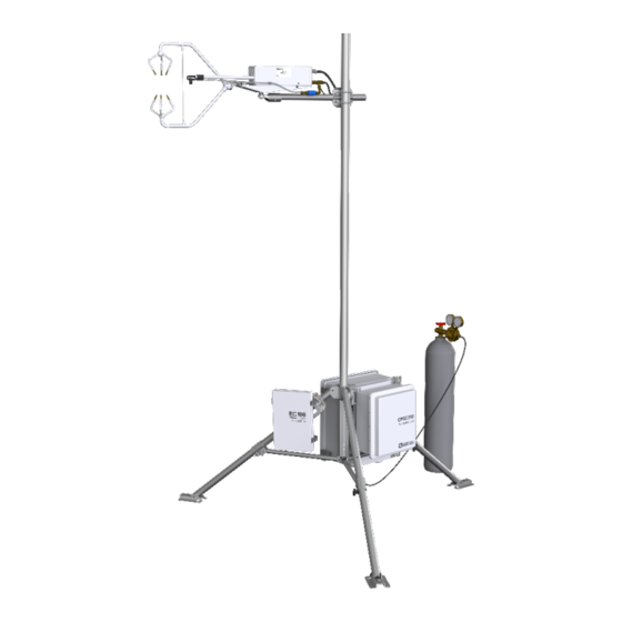
EC100 mounting bracket. CPEC300: Mount the CPEC300 enclosure and the CPEC300 pump module within 3.0 m (10.0 ft) distance. The enclosure and pump module are shown mounted vertically on the CM210 tripod in FIGURE 4-4, but they may also be mounted on the leg of the tripod, triangular tower, or large-diameter pole, depending on the site requirements and the mounting options ordered. -
Page 35: Cm210 Mounting Bracket On A Tripod Mast
FIGURE 5-1. CM210 mounting bracket on a tripod mast The EC155 gas analyzer and CSAT3A sonic anemometer head are mounted on the end of the crossarm using the CM250 leveling mount and the CPEC300-series mounting platform. FIGURE shows mounting for the EC155 with vortex intake. -
Page 36: Plumbing
CPEC300, CPEC306, and CPEC310, respectively. FIGURE shows how a CPEC300 enclosure is connected to the pump module and EC155. The EC155 is connected to the CPEC300 pump module’s Inlet connector and the pump module umbilical cord is connected to the connector labeled Pump Module on the CPEC300 enclosure. -
Page 37: Pump Module
FIGURE 5-5. Plumbing for CPEC310 with optional scrub module 5.2.1 Pump Module For the CPEC300 connect the EC155 to the pump module as shown in FIGURE 5-3. If the EC155 is within 15 m (50 ft) of the pump module, 3/8-in OD tubing is recommended. - Page 38 CPEC300/306/310 Closed-Path Eddy-Covariance Systems Install cylinders in close proximity to the CPEC310 system enclosure. Each cylinder must have a pressure regulator to control the outlet pressure at 10 psig and must have a 1/4-in Swagelok fitting on the outlet. Connect regulators to the valve module inlets using 1/4-in OD tubing or pre-swaged tube assemblies.
-
Page 39: Wiring
Inlet. Wiring 5.3.1 Ground Connections Any CPEC300-series system enclosure and the EC100 electronics must be earth grounded as illustrated in FIGURE 5-7. Ground the tripod and enclosures by attaching heavy gage grounding wire (12 AWG minimum) to the grounding lug found on the bottom of each enclosure. -
Page 40: Ec Sensor Cables
FIGURE 5-8. EC155 and CSAT3A electrical connections; mounting hardware and tubing not shown) NOTE CPEC300-series instruments that are ordered with a CR6, are pre- wired with the appropriate EC100 wiring. For users that need to wire the system, follow the next sections to wire the connection between the EC100 and the CPEC300-series enclosure. -
Page 41: Wiring The Ec100 To A Cpec306 And Cpec310 Enclosure
CPEC300/306/310 Closed-Path Eddy-Covariance Systems NOTE To bring cables into the CPEC306 and CPEC310 enclosure, remove the cap from the cable feedthrough by loosening the thumbscrew and pulling the cap off. NOTE The CPEC306 and CPEC310 wires connect to a DIN rail located inside of the main enclosure. -
Page 42: Pump Module Cable For A Cpec300
FIGURE 5-10, to a user-supplied, 12 Vdc power supply. For the CPEC300, the power cables will be plugged into the orange splicing switches attached to the top of the enclosure, as shown in FIGURE 5-11. -
Page 43: Configure The Easyflux Dl Program
CO , latent heat (H O), sensible heat, ground surface heat (optional), and momentum from any CPEC300-series system with optional GPS and energy balance sensors. The program processes EC data using commonly used corrections in the scientific literature. Because the... - Page 44 O Gas Analyzer with EC100 Electronics CAST3A sonic anemometer CR6 datalogger (housed in EC100) Pump Module • CPEC306 In additional to components listed for CPEC300 above, the CPEC306 includes a: CDM-A116 analog channel expansion module System Enclosure (houses CR6, pump module, CDMA-116 module) •...
-
Page 45: Operation
CPEC300/306/310 Closed-Path Eddy-Covariance Systems If the CPEC300-series system was ordered with the CR6 factory installed, the system is shipped with the EasyFlux DL CR6CP program installed. For users that will install a previously purchased CR6 into a CPEC300-series system or... -
Page 46: Accessing The Constants
LoggerNet, or CRBasic Editor. However, if an older CR6 with smaller CPU memory (i.e., 1 MB) is transferred into a CPEC300-series system, then the constants may only be set using the CRBasic Editor, as described in the section Using CRBasic Editor below. - Page 47 CPEC300/306/310 Closed-Path Eddy-Covariance Systems Press Esc on the CR1000KD keypad at any time to return to the NOTE previous menu or screen. Using LoggerNet The constants may be edited using LoggerNet software on a PC. Use the LoggerNet Connect Screen to connect to the datalogger, and then use the Table Monitor to view the table called Const_Table.
-
Page 48: Example Screen From Crbasic Editor Showing User-Defined Configuration Constants
CPEC300/306/310 Closed-Path Eddy-Covariance Systems FIGURE 6-1. Example screen from CRBasic Editor showing user- defined configuration constants... -
Page 49: Cdma116
Set to – 1 (TRUE) for the CPEC306 or CPEC310 if they include a DVC_CDM_A116 – 1 CDM-A116 device. Set to 0 (FALSE) for the CPEC300. CDM_SN 0000 The serial number of the CDM-A116 CPI_ADDR_CDM The CPI address of the CDM-A116 A custom name the user can give the CDM-A116. - Page 50 CPEC300/306/310 Closed-Path Eddy-Covariance Systems TABLE 6-1. Program Constants Indented constant names indicate they are only applicable if the prior non-indented constant is true/applicable. Constant Name Default Value Description Set to – 1 (TRUE) to set the analyzer readings to zero while zero SET_ZRO –...
- Page 51 CPEC300/306/310 Closed-Path Eddy-Covariance Systems TABLE 6-1. Program Constants Indented constant names indicate they are only applicable if the prior non-indented constant is true/applicable. Constant Name Default Value Description Set to – 1 (TRUE) if using a LI200X or LI200RX, else set to 0 SENSOR_LI200 (FALSE).
-
Page 52: Edit Input Variables
CPEC300/306/310 Closed-Path Eddy-Covariance Systems TABLE 6-1. Program Constants Indented constant names indicate they are only applicable if the prior non-indented constant is true/applicable. Constant Name Default Value Description If using a TE525-series rain gauge, enter the multiplier. Units: mm per tip. Multiplier for TE525MM = 0.1 mm/tip as default, TE525 = TE525_MULT 0.254 mm/tip, TE525WS = 0.254 mm/tip, TE525/WS w/ 8 in... - Page 53 CPEC300/306/310 Closed-Path Eddy-Covariance Systems If a CR1000KD is not available, an alternative option is to review and edit variables using LoggerNet. Under the Connect Screen’s Table Monitor, select the Public Table and then scroll to the appropriate variables. The last column...
- Page 54 CPEC300/306/310 Closed-Path Eddy-Covariance Systems...
- Page 55 CPEC300/306/310 Closed-Path Eddy-Covariance Systems...
-
Page 56: Custom Keypad Menu; Arrows Indicate Submenus
(*) marks variables that are only displayed if the system is a CPEC310, and the double asterisk (**) marks variables that are only displayed if the system is a CPEC300 or CPEC306. In the constants table, indented constants are only applicable if the... -
Page 57: Variables From Initial Configuration Menu
CPEC300/306/310 Closed-Path Eddy-Covariance Systems TABLE 6-2. Variables from Initial Configuration Menu Name of variable in Public Table (when no Station Variable Default Description CR1000KD available) Used to select the barometer to use for measurements of press_source ambient pressure. Set to EB for... - Page 58 CPEC300/306/310 Closed-Path Eddy-Covariance Systems TABLE 6-2. Variables from Initial Configuration Menu Name of variable in Public Table (when no Station Variable Default Description CR1000KD available) span gas through the gas analyzer. If the system is not a CPEC310, this variable is omitted.
-
Page 59: Variables And Settings In Site Var Settings Menu
CPEC300/306/310 Closed-Path Eddy-Covariance Systems TABLE 6-2. Variables from Initial Configuration Menu Name of variable in Public Table (when no Station Variable Default Description CR1000KD available) Coefs variable to TRUE in order to apply. The program will return Reset Coefs to FALSE once the change has been applied. - Page 60 CPEC300/306/310 Closed-Path Eddy-Covariance Systems TABLE 6-3. Variables and Settings in Site Var Settings Menu Name of variable in Public Table (when no CR1000KD Station Variable Units Default Description available) Distance along the sonic x-axis IRGA Coord x 0.15020 between the sonic sampling volume separation_x_IRGA and the EC155 gas analyzer intake.
- Page 61 CPEC300/306/310 Closed-Path Eddy-Covariance Systems TABLE 6-3. Variables and Settings in Site Var Settings Menu Name of variable in Public Table (when no CR1000KD Station Variable Units Default Description available) The site altitude or elevation above Altitude 1356 altitude sea level.
- Page 62 CPEC300/306/310 Closed-Path Eddy-Covariance Systems TABLE 6-3. Variables and Settings in Site Var Settings Menu Name of variable in Public Table (when no CR1000KD Station Variable Units Default Description available) Planar-fit beta angle used to rotate the wind when the mean horizontal ≥...
-
Page 63: Data Retrieval
FALSE prfm_auto_zero_span_flg measurements upon completion of the zero/span. This variable is ommitted if the system is a CPEC300 or CPEC306 (i.e., no valve module). For CPEC300 and CPEC306 systems, select TRUE to disable the pump. Set to FALSE to enable the pump. For... -
Page 64: Output Tables
TABLE are approximations for new cards. CAUTION Campbell Scientific recommends and supports only the use of microSD cards obtained from Campbell Scientific. These cards are industrial grade and have passed Campbell Scientific hardware testing. Use of consumer grade cards substantially increases the risk of data loss. -
Page 65: Data Output Tables
CPEC300/306/310 Closed-Path Eddy-Covariance Systems constant ONE_FULL_TABLE from FALSE to TRUE (see Section 6.2, Set Constants , for details on changing constants). (p. 36) TABLE 6-6. Data Output Tables Memory on Memory on Table Name Description Recording Interval CR6 CPU SD Card... -
Page 66: Data Fields In The Time_Series Data Output Table
CPEC300/306/310 Closed-Path Eddy-Covariance Systems TABLES through 6-14 give a description of all data fields found in each data output table and when each data field is included in the table. NOTE Prior to coordinate rotations, the orthogonal wind components from the sonic anemometer are denoted as U... -
Page 67: Data Fields In The Diagnostic Output Table
CPEC300/306/310 Closed-Path Eddy-Covariance Systems TABLE 6-7. Data Fields in the Time_Series Data Output Table Data Field Data Field Name Units Description Included For CPEC310 this identifies the current sampling regime. Bits 0 through 3 correspond to the current sampling site, and bit 4 is the omit flag. For Binary computing fluxes, filter all values not equal to 1. -
Page 68: Data Field In The Ec100_Config_Notes Output Table
CPEC300/306/310 Closed-Path Eddy-Covariance Systems TABLE 6-8. Data Fields in the Diagnostic Output Table Data Field Data Field Name Description Included irga_startup_f Startup diagnostic flag Always irga_motor_spd_f Motor speed diagnostic flag Always Thermoelectric cooler (TEC) temperature irga_tec_tmpr_f Always diagnostic flag irga_src_pwr_f... -
Page 69: Data Fields In The Flux_Amerifluxformat Output Table
CPEC300/306/310 Closed-Path Eddy-Covariance Systems TABLE 6-9. Data Field in the EC100_Config_Notes Output Table Data Field Name Units Description Data Field Included A parameter indicating the sensor used by EC100 for ambient pressure (0 for EC100 press_source – Basic Barometer, 1 for user/custom... - Page 70 CPEC300/306/310 Closed-Path Eddy-Covariance Systems TABLE 6-10. Data Fields in the Flux_AmeriFluxFormat Output Table Data Field Data Field Name Units Description Included Average H O molar mixing ratio mmol·mol Always (dry basis) H2O_SIGMA mmol·mol Standard deviation of H Always µmol·m ·s...
- Page 71 CPEC300/306/310 Closed-Path Eddy-Covariance Systems TABLE 6-10. Data Fields in the Flux_AmeriFluxFormat Output Table Data Field Data Field Name Units Description Included kg·m ·s Momentum Flux Always Result of steady state and integral TAU_SSITC_TEST – turbulence characteristics for FC Always according to Foken et al. (2004)
-
Page 72: Data Fields In The Flux_Csformat Data Output Table
CPEC300/306/310 Closed-Path Eddy-Covariance Systems TABLE 6-10. Data Fields in the Flux_AmeriFluxFormat Output Table Data Field Data Field Name Units Description Included Average volumetric soil water If CS650 or CS655 SWC_x_1_1 content. x is an index for the used number of sensors. - Page 73 CPEC300/306/310 Closed-Path Eddy-Covariance Systems TABLE 6-11. Data Fields in the Flux_CSFormat Data Output Table Data Field Name Units Description Data Field Included Overall quality grade for Hs following H_QC grade Foken et al. 2012. See Appendix Always quality grade definitions.
- Page 74 CPEC300/306/310 Closed-Path Eddy-Covariance Systems TABLE 6-11. Data Fields in the Flux_CSFormat Data Output Table Data Field Name Units Description Data Field Included Relative humidity calculated from RH_1_1_1 TA_1_1_1, H O mixing ratio, and Always pressure. Average dewpoint temperature T_DP_1_1_1 deg C...
- Page 75 CPEC300/306/310 Closed-Path Eddy-Covariance Systems TABLE 6-11. Data Fields in the Flux_CSFormat Data Output Table Data Field Name Units Description Data Field Included Standard deviation of sonic T_SONIC_SIGMA deg C Always temperature decimal Compass direction in which the sonic sonic_azimuth Always...
- Page 76 CPEC300/306/310 Closed-Path Eddy-Covariance Systems TABLE 6-11. Data Fields in the Flux_CSFormat Data Output Table Data Field Name Units Description Data Field Included Average incoming long wave If CNR4 or NR01 LW_IN W·m radiation is used If CNR4 or NR01 LW_OUT W·m...
-
Page 77: Data Fields In The Flux_Notes Output Table
CPEC300/306/310 Closed-Path Eddy-Covariance Systems TABLE 6-11. Data Fields in the Flux_CSFormat Data Output Table Data Field Name Units Description Data Field Included Distance upwind where the maximum FETCH_MAX Always contribution to the footprint is found Upwind distance that contains 90% of... - Page 78 CPEC300/306/310 Closed-Path Eddy-Covariance Systems TABLE 6-12. Data fields in the Flux_Notes Output Table Data Field Data Field Name Units Description Included Covariance of streamwise and UW_cov m·s Always crosswind after coordinate rotations Covariance of crosswind and vertical VW_cov m·s Always...
- Page 79 CPEC300/306/310 Closed-Path Eddy-Covariance Systems TABLE 6-12. Data fields in the Flux_Notes Output Table Data Field Data Field Name Units Description Included UxCO2_Cov mg·m ·s Covariance of U and CO density Always UyCO2_Cov mg·m ·s Covariance of U and CO density...
- Page 80 CPEC300/306/310 Closed-Path Eddy-Covariance Systems TABLE 6-12. Data fields in the Flux_Notes Output Table Data Field Data Field Name Units Description Included Number of IRGA samples with any irga_bad_data_f_Tot count Always IRGA diagnostic flag set high Number of gas analyzer samples with...
- Page 81 CPEC300/306/310 Closed-Path Eddy-Covariance Systems TABLE 6-12. Data fields in the Flux_Notes Output Table Data Field Data Field Name Units Description Included Number of gas analyzer samples with irga_htr_ctrl_off_f_Tot count Always heater control off diagnostic flag Number of gas analyzer samples with...
- Page 82 CPEC300/306/310 Closed-Path Eddy-Covariance Systems TABLE 6-12. Data fields in the Flux_Notes Output Table Data Field Data Field Name Units Description Included Number of seconds in the interval that pump_fan_secs Always the pump fan was on If the system Average temperature of the valve...
- Page 83 CPEC300/306/310 Closed-Path Eddy-Covariance Systems TABLE 6-12. Data fields in the Flux_Notes Output Table Data Field Data Field Name Units Description Included Average relative humidity inside sample cell_RH Always cell Alpha angle used for coordinate decimal rotations (regardless of planar fit or...
- Page 84 CPEC300/306/310 Closed-Path Eddy-Covariance Systems TABLE 6-12. Data fields in the Flux_Notes Output Table Data Field Data Field Name Units Description Included altitude Altitude or elevation above sea level Always Time offset in hours between local time UTC_offset Always zone and UTC/GMT...
- Page 85 CPEC300/306/310 Closed-Path Eddy-Covariance Systems TABLE 6-12. Data fields in the Flux_Notes Output Table Data Field Data Field Name Units Description Included Maximum number of scans to lag gas analyzer or fine-wire thermocouple data with respect to sonic data when doing...
-
Page 86: Data Fields In The Zero_Span_Notes Table
CPEC300/306/310 Closed-Path Eddy-Covariance Systems TABLE 6-12. Data fields in the Flux_Notes Output Table Data Field Data Field Name Units Description Included Average panel temperature of the CDM-A116, where x at the end of the name is an index from 1 to 4,... - Page 87 CPEC300/306/310 Closed-Path Eddy-Covariance Systems TABLE 6-13. Data Fields in the Zero_Span_Notes Table Data Field Name Units Description Data Field Included valve_flow_zero L∙min Flow rate of zero air during zero Always Measured CO mixing ratio during CO2_CO2span µmol∙mol Always span Measured H...
-
Page 88: Program Sequence Of Measurement And Corrections
CPEC300/306/310 Closed-Path Eddy-Covariance Systems TABLE 6-14. Data Field in the System_Operatn_Notes Output Table Data Field Name Units Description Data Field Included Text A message describing a change of system Message Always string status Text Additional information corresponding to the Current Value... -
Page 89: Zero And Span
More details are found in Section 7.1.2, CPEC310 Manual H2O Span (p. 86). CPEC300 and CPEC306 systems require the user to manually setup and initiate the zero, CO span, and/or H O span since these systems do not include a valve module. -
Page 90: Variables Found In Menus For Zero And Span
CPEC300/306/310 Closed-Path Eddy-Covariance Systems NOTE TABLE lists the variables found within the Attendant Zero/Span menu and its submenus. The table also shows the equivalent variable names in the datalogger’s Public Table. If a CR1000KD is not available, performing a zero/span may... - Page 91 CPEC300/306/310 Closed-Path Eddy-Covariance Systems TABLE 7-1. Variables Found in Menus for Zero and Span Name of variable in Public Table (when no Variable Name Default Description CR1000KD available) This is a read-only variable showing the temperature in °C of Scrb Tmpr the scrub module.
- Page 92 CPEC300/306/310 Closed-Path Eddy-Covariance Systems TABLE 7-1. Variables Found in Menus for Zero and Span Name of variable in Public Table (when no Variable Name Default Description CR1000KD available) This is a read-only variable showing the number of seconds Sec On Site...
-
Page 93: User-Initiated Zero/Span For Cpec310
CPEC300/306/310 Closed-Path Eddy-Covariance Systems User-Initiated Zero/Span for CPEC310 Before beginning a user-initiated zero/span, the temperature of the valve module (and scrub module if applicable) must be within operating range. Select the submenu Valv Tmpr Ctrl (or Valv/Scrub Tmpr Ctrl if using the scrub module), found under the Attendant Zero/Span menu by highlighting it and pressing Enter. -
Page 94: Site Sequence And Timing In The Auto Zero And Span Cycle
CPEC300/306/310 Closed-Path Eddy-Covariance Systems TABLE 7-2. Site Sequence and Timing in the Auto Zero and Span Cycle Step in Omit Status (seconds of Auto Site measurements that are Description Timing (seconds) Zero/Span Name ommitted from Cycle statistics or stored data) -
Page 95: Cpec310 Manual H 2 O Span
CPEC300/306/310 Closed-Path Eddy-Covariance Systems TABLE 7-2. Site Sequence and Timing in the Auto Zero and Span Cycle Step in Omit Status (seconds of Auto Site measurements that are Description Timing (seconds) Zero/Span Name ommitted from Cycle statistics or stored data) -
Page 96: User-Initiated Manual Zero/Span For Cpec300 Or Cpec306
ECMon. User-Initiated Manual Zero/Span for CPEC300 or CPEC306 Neither the CPEC300 nor the CPEC306 contains a valve module, therefore, these systems require the user to manually connect and flow a zero or span gas through the gas analyzer. The tubing carrying the zero or span gas should be... -
Page 97: Cpec300/Cpec306 Manual Co 2 Span
CPEC300/306/310 Closed-Path Eddy-Covariance Systems cell, and then return to a low flow (< 0.5 L/min) when preparing to check and/or set the zero. As zero gas is flowing, watch the CO and H O readings until they indicate that the zero gas has flushed the sample cell and equilibrium has been reached. -
Page 98: Maintenance And Troubleshooting
Enclosure Desiccant Check the humidity indicator card in the mesh pocket in the CPEC300-series system enclosure door and the EC100 enclosure door. The humidity indicator card has three colored circles that indicate the percentage of humidity (see FIGURE 4-23). -
Page 99: Ec155 Molecular Sieve Bottles
). If recalibration is deemed necessary, contact Campbell Scientific. Repair All of the CPEC300-series systems are designed to give years of trouble-free service with reasonable care. However, if factory repair is needed, contact Campbell Scientific to obtain an RMA number. An RMA number and product safety documents are required prior to any repair shipments being accepted at Campbell Scientific. -
Page 100: Easyflux Dl Cr6Cp Process Flow
Appendix A. EasyFlux DL CR6CP Process Flow Sequence of Program Functions Every SCAN_INTERVAL (default 100 ms) Collect raw data from GPS sensor, battery voltage, CDM panel temp, FW, and rain gauge ⇩ Store FW measurements in a table to be used later to align with sonic data ⇩... - Page 101 Appendix A. EasyFlux DL CR6CP Process Flow Send sonic data to covariance tables to be included for 5 min and averaging interval covariances Parse out gas diagnostic data, and filter bad gas data from being included in statistical data ⇩ Calculate climate and gas variables (e.g., e, rho_d, rho_a, Td, CO2_mixratio, H2O_mixratio, RH) ⇩...
- Page 102 Appendix A. EasyFlux DL CR6CP Process Flow If using self-calibrating heat flux plates and a new calibration interval has started, perform the auto calibration ⇩ If station variables have changed, save new values to memory ⇩ System power control (if needed, power down gas analyzer and pump) ⇩...
- Page 103 Appendix A. EasyFlux DL CR6CP Process Flow ⇩ Calculate value for steady state test using the 30-minute momentum covariances and the 5-minute momentum covariances. (see EasyFlux DL CR6OP manual, Appendix F on Data Quality Grading.) ⇩ Calculate the overall quality grade for momentum flux. (See EasyFlux DL CR6OP manual, Appendix F on Data Quality Grading.) ⇩...
- Page 104 Appendix A. EasyFlux DL CR6CP Process Flow Calculate covariances of and wind components for each lagged dataset and do coordinate rotation on covariances. ⇩ Find the dataset with the physically possible lag that maximizes the covariance of and vertical wind. Use this dataset for the FLUX_AMERIFLUXFORMAT and FLUX_CSFORMAT output tables.
- Page 105 Appendix A. EasyFlux DL CR6CP Process Flow Calculate soil surface energy flux for the averaging interval. (See EasyFlux DL CR6OP manual, Appendix H on Surface Flux.) Get calculated measurements of H, LE, and Rnet for the averaging If energy balance interval.
-
Page 106: Sampling Site, Regime, And Mode
Appendix B. Sampling Site, Regime, and Mode Sampling sites, regimes, and modes are applicable to the CPEC310 and help distinguish certain states of the system. A sampling site refers to a particular valve selection or air sampling source. TABLE provides a list of the defined sampling sites. - Page 107 Appendix B. Sampling Site, Regime, and Mode TABLE B-1. Site Numbers, Text Descriptors, and Descriptions Text Descriptor of Site Site (used on Number CR1000KD display) Description set CO2 Set CO span chk H2O Check H O Span set H2O Set H O span Idle or equilibration with ambient equilib...
- Page 108 Appendix B. Sampling Site, Regime, and Mode TABLE B-2. Mode Names and Descriptions Mode Name Description IRG_SLP IRGA sleep mode. This mode powers down the gas analyzer and pump and leaves the CSAT3A powered on and making measurements. AUTO_ZS Automatic zero and span mode. This mode automatically will check and/or set the zero and CO span of the gas analyzer.
-
Page 109: Wiring The Cr6 And Optional Energy Balance Sensors
The minimum required equipment to operate EasyFlux DL CR6CP is one of the CPEC300-series systems with its core components, as described in the introduction. The additional sensors described in Sections C.1.3 through C.1.12 are optional. Many of the optional sensors are only available for a CPEC306 or CPEC310 system since it includes a CDM-A116 module. -
Page 110: Cdm-A116 Module (Cpec306 And Cpec310 Only
CPEC310 should already have a CDM-A116 installed, connected to the CR6, and configured, but in the case it needs to be reconfigured or in case a CDM- A116 is being manually added to a CPEC300, prepare it as follows: Connect the CDM-A116 to a 10-32 Vdc power source. -
Page 111: Temperature And Relative Humidity Probe
Appendix C. Wiring the CR6 and Optional Energy Balance Sensors TABLE C-3. Default Wiring for Fine-Wire Thermocouple Sensor Quantity Wire Description Color CDM-A116 Terminal Signal Purple CDM Diff 6H FW05, FW1, or Signal Reference CDM Diff 6L 0 or 1 CDM AG ⏚... -
Page 112: Radiation Measurements Option 2
Appendix C. Wiring the CR6 and Optional Energy Balance Sensors TABLE C-5. Default Wiring for Radiation Measurement Option 1 CDM-A116 Terminal Sensor Quantity Wire Description Color Radiation Signal CDM Diff 1H NR-LITE2 Net Signal Reference Blue CDM Diff 1L 0 or 1 Radiometer CR6 AG ⏚... -
Page 113: C-6. Default Wiring For Radiation Measurements Option 2
Appendix C. Wiring the CR6 and Optional Energy Balance Sensors TABLE C-6. Default Wiring for Radiation Measurements Option 2 CDM-A116 Sensor Quantity Wire Description Color Terminal Pyranometer Up Signal Red (cbl 1) CDM Diff 1H Pyranometer Up Blue (cbl 1) CDM Diff 1L Reference Pyranometer Down Signal... -
Page 114: Precipitation Gage
Appendix C. Wiring the CR6 and Optional Energy Balance Sensors C.18 Precipitation Gage EasyFlux DL CR6OP can support a single tipping rain gage such as the TE525MM, or a precipitation gage can be omitted. The default wiring for the precipitation gage is shown in TABLE C-7. TABLE C-7. -
Page 115: Soil Water Content
Appendix C. Wiring the CR6 and Optional Energy Balance Sensors C.1.10 Soil Water Content EasyFlux DL CR6CP supports one of two models of soil water content sensors: CS650 or CS655; up to two of one model is supported. The default wiring for each is shown in TABLE C-9. -
Page 116: Soil Heat Flux Plates
Appendix C. Wiring the CR6 and Optional Energy Balance Sensors C.1.11 Soil Heat Flux Plates EasyFlux DL CR6CP can support from zero to four soil heat flux plates. They can be the HFP01 plates (non-self-calibrating) or the HFP01SC (self- calibrating) plates. The default wiring for the HFP01 standard soil heat flux plates is shown in TABLE C-10. -
Page 117: C-11. Default Wiring For Soil Heat Flux Plates (Self Calibrating)
Appendix C. Wiring the CR6 and Optional Energy Balance Sensors TABLE C-11. Default Wiring for Soil Heat Flux Plates (Self Calibrating). Sensor Quantity Wire Description Color CDM-A116 Terminal Signal White CDM Diff 9H CDM AG ⏚ Signal Reference Green CDM AG ⏚ Shield Clear Heater Signal... -
Page 118: System Diagnostic Word
Appendix D. System Diagnostic Word The system diagnostic word, system_diag, is an aggregate or sum of the system diagnostic bits or flags listed below in TABLE D-1. TABLE D-1. Description of Bits for System Diagnostic Word. Decimal Name Function Sonic error. If any error condition or diagnostic flag is set on the sonc_er sonic anemometer, this bit is set. -
Page 119: Quality Grading
Appendix E. Quality Grading TABLES below show the quality grade definitions. Refer to Foken et al. (2012) for more details, and refer to Appendix F of the EasyFluxDL for CR6OP for more details on the implementation in the datalogger program. TABLE E-1. -
Page 120: Non-Stationary, Relative Integral Turbulence Characteristic, And Wind Direction In Sonic Instrument Coordinate System
Appendix E. Quality Grading TABLE E-2. Overall grades for each flux variable by the grades of relative non-stationary, relative integral turbulence characteristic, and wind direction in sonic instrument coordinate system.1/ wnd_dir_sonic Overall quality Relative non- Relative integral turbulence grade Wind direction stationarity characteristic 1 (best) -
Page 121: Cpec300 Series Diagnostics
Appendix F. CPEC300 Series Diagnostics CPEC300 series diagnostic information is available to the user in any of three different formats: status text strings, status Boolean variables, and diagnostic flags encoded as binary bits in integer variables. With these multiple avenues... - Page 122 There are multiple possible causes and each has a different message reported in irga_status: ERROR: IRGA is OFF - Check BattVolt is displayed if BattVolt_OK = False. This usually means the EC155 has been powered down by the CPEC300 because the battery voltage has dropped below the shutdown limit.
- Page 123 ERROR: Sonic problem - Check diag_sonic is displayed when a bit is set in diag_sonic. This usually means the sonic path is blocked. If there is no obvious reason for the problem, such as water on the face of a transducer, contact Campbell Scientific for assistance.
- Page 124 ERROR: Pump is disabled - IRGA is OFF is displayed if the • CPEC300 has stopped the pump because the IRGA is off. This correlates with irga_OFF = True and could be a result of the EC155 automatically powering down because its source temperature is outside its operating range.
- Page 125 • ERROR: press_offset is zero - turn pump off and set DO_P_offset = true is displayed if press_offset = 0. The CPEC300 requires a recent measurement of the pressure offset which is given as the sample cell pressure measured with no flow. The pressure offset is set to zero when it is no longer valid.
-
Page 126: Status Boolean Variables
(p. F-1) for which EC_mode = False, should be excluded from EC calculations. This variable is also used by the CPEC300 program to determine the relevance of some of the error conditions. For example, the pump flow is relevant only in EC mode, but the battery voltage is always relevant. - Page 127 55 °C) and is set to False if it is outside this range. This check is performed continuously, and pump_tmpr_OK is set accordingly. If a CPEC300 system is in EC mode, bit 5 of diag_cpec will be set if pump_tmpr_OK = False to indicate there is a problem with the pump temperature.
-
Page 128: Cpec300 System Diagnostic Words
Diagnostic word diag_cpec flags several conditions specific to the normal operating range for a CPEC300 system. Some of these conditions may or may not be relevant, depending on if a CPEC300 system is in EC mode. The diagnostic word diag_cpec, includes only the diagnostic flags that are relevant depending on EC_mode. - Page 129 Bit 9 of diag_cpec is equivalent to BattVolt_OK = False. It indicates the power source for a CPEC300 system has dropped below the acceptable voltage limit. This triggers a CPEC300 system to power down as much of the system as possible to prevent a deep discharge that might damage the user’s battery.
- Page 130 ERROR: Battery voltage is in deadband. This situation can arise if the battery voltage was previously below the shutdown limit causing a CPEC300 system to set the battery voltage error flag and shut the system down. Subsequently the battery voltage recovered enough to be in the deadband (above the shutdown limit but below the turn-on limit).
- Page 131 If the flow is not at the setpoint, check the value of pump_control. This variable controls the speed of the pump, from 0.0 (off) to 1.0 (full speed). In normal operation, when the flow falls below the setpoint, the CPEC300 will F-11...
- Page 132 Bit 5 of diag_cpec indicates the pump temperature is outside its operating range. This triggers the CPEC300 to shut down the pump to protect the pump from possible damage. This check is performed even if the pump is turned off.
- Page 133 If it is NAN, this indicates a problem with the temperature measurement. Make sure the pump module cable is connected to the “Pump Module” connector on the bottom of the CPEC300 system enclosure. Next, compare pump_tmpr to the operating range (0 to 55 °C). The pump will be disabled if the pump is too cold.
- Page 134 ZeroAir valve (1) is selected. The scrub module has a pump to push the zero air through the valve module to the IRGA. The CPEC300 fully opens the flow control valve by setting valveControl = 1. The acceptable range for valve_flow is between 0.5 and 3.0 LPM.
- Page 135 The proportional control valve will be fully closed at any value of valveControl below approximately 0.3. If valveControl is 1.0 and the flow is too low and a CPEC300 system is accessible, check the indicator lights on the valve module. One of the inlet valve lights (Zero Air, CO Span 1, etc.) should be illuminated.
- Page 136 CPEC300 system fully opens the flow control valve by setting valveControl = 1. The acceptable range for valve_flow is between 0.5 and 3.0 LPM. If a CPEC300 system is accessible, check the indicator lights on the valve module as described above. Also check the tubing connection between the scrub module and the valve module inlet.
- Page 137 If the heater is on and the valve module is too cold, check the ambient temperature. The CPEC300 is rated for temperatures from −30 to 50 °C. If the system is started in cold weather after being turned off for several hours, it may take up to 15 minutes to warm up to operating temperature.
- Page 138 Zero_Span). If the heater is on and the scrub module is too cold, check the ambient temperature. The CPEC300 is rated for temperatures from − 30 to 50 °C. If the system is started in cold weather after being turned off for several hours, it may take up to 20 minutes to warm up to operating temperature.
-
Page 139: Public Variables
Appendix G. Public Variables Some of the variables in the CPEC300 system’s CRBasic program are included in the Public table. These public variables may be displayed or edited with a keyboard display or PC. Other program variables are hidden from the user to reduce clutter in the Public table. - Page 140 Appendix G. Public Variables TABLE G-1. CPEC300 public variables When Defined Usage Variable Name Units Description always SONIC diag_sonic CSAT3A diagnostic word always IRGA mixing ratio, relative to µmol∙mol dry air always IRGA O vapor mixing ratio, µmol∙mol relative to dry air...
- Page 141 Appendix G. Public Variables TABLE G-1. CPEC300 public variables When Defined Usage Variable Name Units Description VALVE_MODULE USER DO_P_offset Set = True to measure the pressure offset VALVE_MODULE INFO press_offset Sample cell pressure measured with no flow; used to infer...
- Page 142 Appendix G. Public Variables TABLE G-1. CPEC300 public variables When Defined Usage Variable Name Units Description always INFO panel_tmpr ºC Temperature of the datalogger wiring panel always INFO process_time µs Time to process the scan (a copy of ProcessTime from the...
- Page 143 Appendix G. Public Variables TABLE G-1. CPEC300 public variables When Defined Usage Variable Name Units Description always CONFIG SET_SPAN_1 Set = True to set the CO span during automatic zero/span sequences always CONFIG CHECK_SPAN2 Set = True to measure CO...
-
Page 144: Output Variables
2 GB memory card will store data for approximately four weeks before the CPEC300 program begins to delete old files to make room for new files. If no valve module is used, the time-series files are slightly smaller, approximately 55 kB. - Page 145 Appendix H. Output Variables TABLE H-1. Values stored in table ts_data Compile Variable Switch Name Units Description pump_flow Sample pump speed, converted to volumetric flow rate valve_number Valve number (0 to 6); determines which zero/span valve is selected valve_flow zero/span flow CO2_signal Relative strength of the infrared signal in the CO absorption...
- Page 146 The rest of the values provide diagnostic information about the CPEC300 system. The value of the compile switches as shown in TABLE depends on the .
- Page 147 Appendix H. Output Variables TABLE H-2. Values stored in table flux Compile Switch Variable Name Units Description wind_speed m∙s Average wind speed wind_vector_mag m∙s Magnitude of average wind vector wind_dir_sonic degrees direction of average wind vector stdev_wind_dir degrees Standard deviation of wind direction wind_dir_compass degrees Wind direction in compass coordinates...
- Page 148 Appendix H. Output Variables TABLE H-2. Values stored in table flux Compile Switch Variable Name Units Description source_tmpr_Avg ºC Average source temperature pump_ON_Avg Fraction of time the pump was on pump_flow_Avg Average pump flow pump_control_Avg Average pump control value pump_press_Avg Average pump pressure diag_CPEC_Avg Average of diag_cpec...
- Page 149 Appendix H. Output Variables at seven records per sequence, and sequences run every hour). The CPU has storage allocated for 500 records (3 days). The zero_span table is defined only if VALVE_MODULE = True. As a result, only the last five values, associated with the scrub module, are optional depending on the SCRUB_MODULE compile switch.
- Page 150 Appendix H. Output Variables TABLE H-3. Values stored in table zero_ span Compile Switch Variable Name Units Description BattVolt_Avg Average supply voltage BattVoltOK_Avg Fraction of time the system was not shut down because the supply temperature had dropped below the limit slow_samples Number of samples included in the average for values measured in the slow scan...
- Page 151 ERROR: Zero/Span sequence aborted - Check valve temperature • If a CPEC300 system attempts to set the IRGA zero or span as part of a zero/span sequence and there is a problem identified (diag_cpec is nonzero), the CPEC300 system will skip the zero or span setting step, continue the rest of the sequence, and display one of the following messages.
- Page 152 RECORD Record number message_str Message explaining why the record was written mode_status Operating state of the CPE300 cpec_status Overall status of the CPEC300 sonic_status Status of the CSAT3A irga_status Status of the EC155 pump_status Status of the sample pump valve_status...
- Page 153 (a copy of BuffDepth from the Status table) config_history The user may change the configuration of the CPEC300 program at any time, as discussed in Section 6, Configure the EasyFlux DL Program . All the (p. 34)
- Page 154 Appendix H. Output Variables TABLE H-5. Values stored in table config_history Variable Name Units Description CO2_SPAN_PPM µmol∙mol mixing ratio in the CO span cylinder USE_DIFF_PRESS Set = True to enable the EC155 differential pressure sensor CHECK_ZERO Set = True to enable automatic zero/span sequences SET_ZERO Set = True to set the zero during automatic zero/span sequences CHECK_SPAN1...
-
Page 155: Control Bits
Internet. Alternately, follow the step-by-step troubleshooting instructions as a guide through the conversion process. Note: the CPEC300 controls power to the heaters and fans with a 16-channel control module, the SDM-CD16S. This same module controls the valves and the scrub pump, as noted in the table. - Page 156 Appendix I. Control Bits bits, subtract 256 from ControlBits and compare the remainder to the bit values below. If ControlBits is greater than 127, this indicates bit 8 of ControlBits is set. This means the valve module fan is on. To decode other temperature control bits, subtract 128 from ControlBits and compare the remainder to the bit values below.
-
Page 157: Using Swagelok Fittings
Appendix J. Using Swagelok Fittings This appendix gives a few tips on using Swagelok tube fittings. For more information, consult your local Swagelok dealer or visit their web site at www.swagelok.com. General Notes: • Do not use fitting components from other manufacturers – they are not interchangeable with Swagelok fittings. -
Page 158: Common Replacement Parts
J.2 Common Replacement Parts Tubing Campbell Scientific can provide several types and sizes of plastic tubing as shown in TABLE J-1. A tubing cutter, can be used to cut these tubes. TABLE J-1. Available plastic tubing sizes, construction, and usage guidelines... -
Page 159: J-3. Dimensions And Part Numbers For Swagelok Ferrules
Appendix J. Using Swagelok Fittings Tubing inserts Inserts are recommended for use in plastic tubing. These inserts become permanently attached to the tubing at the first assembly, so spare inserts may be needed for replacing the ends of tubing. FIGURE J-1. Swagelok insert TABLE J-2. -
Page 160: Swagelok Plug
Appendix J. Using Swagelok Fittings TABLE J-3. Dimensions and part numbers for Swagelok ferrules Tubing OD (in) Swagelok part number (front/back) B-1013-1/B-1014-1 Plugs Swagelok plugs are used to plug a fitting when its tube is disconnected. It is strongly recommended to plug all fittings to keep them clean. Spare plugs may be needed if they become lost or damaged. -
Page 161: J-5. Dimensions And Part Numbers For Swagelok Caps
Appendix J. Using Swagelok Fittings TABLE J-5. Dimensions and part numbers for Swagelok caps Tubing OD (in) Swagelok part number B-200-C B-400-C B-600-C B-810-C B-1010-C... -
Page 162: Cpec310 Scrub Module Installation, Operation, And Maintenance
Appendix K. CPEC310 Scrub Module Installation Operation and Maintenance The CPEC310 Scrub Module provides a stream of air that has been scrubbed of and H O and is used for zeroing the EC155. The module is housed in a fiberglass enclosure that can generally be mounted to the same structure as the CPEC310 system enclosure. -
Page 163: Scrub Module Specifications
Appendix K. CPEC310 Scrub Module Installation, Operation, and Maintenance The CPEC310 scrub module pump pulls ambient air through three bottles of molecular sieve and pushes it to the valve module. The ambient air inlet and zero air outlet fittings are on the bottom of the enclosure. It uses a small diaphragm pump that is mounted in an insulated, temperature-controlled box inside the weather-tight fiberglass enclosure. -
Page 164: Maintenance
Appendix K. CPEC310 Scrub Module Installation, Operation, and Maintenance same way as mounting other CPEC310 enclosures as described in Section 5.1, Mounting (p. 24) Connect the scrub module cable to the CPEC310 system enclosure, receptacle marked Scrub Module. Remove the Swagelok plugs from the inlet and outlet and store them in the mesh pocket in the door. -
Page 165: Interior Of Cpec310 Scrub Module With Tubing And Cover Removed
Appendix K. CPEC310 Scrub Module Installation, Operation, and Maintenance Disconnect the fully exposed black tube (S-shaped and tied to the center of the cover as shown in FIGURE K-2) at both ends. This tube remains captive to the cover plate. NOTE Disconnecting this tube ensures the bottles are not pressurized when the cover is removed. -
Page 166: Empty Bottle Showing The Top (On The Right With Spring) And
Appendix K. CPEC310 Scrub Module Installation, Operation, and Maintenance FIGURE K-4. Empty bottle showing the top (on the right with spring) and bottom (left) caps 10. Remove the spent molecular sieve in accordance to local ordinances and the manufacturer’s Safety Data Sheet. 11. -
Page 167: Cpec300 Series Pump Replacement
Appendix L. CPEC300 Series Pump Replacement L.1 Introduction A properly maintained CPEC300 system will exceed the lifetime of the system’s pump. However, this section provides step-by-step instructions for the user to replace the system pump, rather than needing to return the pump enclosure to Campbell Scientific for replacement. -
Page 168: Module Enclosure
Appendix L. CPEC300 Series Pump Replacement FIGURE L-2. Upright filter unit in enclosure With the filter assembly removed from the CPEC300 system pump module enclosure, remove the six #4 screws (FIGURE L-3) from the pump assembly. FIGURE L-3. Location of #4 screws of pump assembly Once the screws are removed, fold back the pump assembly from the shell bottom as shown in FIGURE L-4. -
Page 169: Removal Of Original Pump Module Inner Plate And Replacement With New Inner Plate Provided In Pump Replacement Kit
Appendix L. CPEC300 Series Pump Replacement FIGURE L-4. Exposed CPEC300 pump assembly NOTE As of May 2017, replacement pumps shipping from Campbell Scientific, Inc. have the wire exiting the pump from the top (original pumps had the wire exiting the side of the pump). To... - Page 170 Appendix L. CPEC300 Series Pump Replacement Remove the paper from the back of the adhesive tape on the new inner plate (FIGURE L-6) and adhere to the foam in the same location as the original plate paying attention to the direction of the notch (FIGURE L-7).
- Page 171 Appendix L. CPEC300 Series Pump Replacement 8. Remove pump connector from the pump electronics (FIGURE L-8). FIGURE L-8. Location of pump connector in CPEC300 pump electronics Gently lift the pump assembly from foam, leaving the tubes attached. Turn it over and remove the two self-tapping #6 screws that attach the pump to the metal box, as shown in FIGURE L-9.
-
Page 172: Installation
11. Remove the pump from the assembly. L.3 Installation To reinstall a CPEC300 pump, carry out the following steps: Position the pump with the label up and connect the coiled tubing on both sides of the pump (see FIGURE L-11). Blue tubing connects the inlets and red connects the outlets as directional arrows show on the side of the pump (FIGURE L-12). - Page 173 FIGURE L-13. Proper positioning of CPEC300 in shell cover Hold the pump assembly securely to the shell cover while replacing the shell cover to the shell bottom.
- Page 174 Appendix L. CPEC300 Series Pump Replacement NOTE Hold the fitting with a backup wrench to make sure the fitting does not unscrew from the filter holder lid. Be careful to not overtighten the fittings as this could cause damage to the hardware. Finger tighten the fittings first, then snug slightly with a wrench.
- Page 175 Campbell Scientific Worldwide Offices Australia Germany Location: Garbutt, QLD Australia Location: Bremen, Germany Email: Email: info@campbellsci.com.au info@campbellsci.de Website: www.campbellsci.com.au Website: www.campbellsci.de Brazil South Africa Location: São Paulo, SP Brazil Location: Stellenbosch, South Africa Email: andread@campbellsci.com.br Email: sales@csafrica.co.za Website: Website: www.campbellsci.com.br www.campbellscientific.co.za...
Need help?
Do you have a question about the CPEC300 and is the answer not in the manual?
Questions and answers