Table of Contents
Advertisement
Quick Links
Advertisement
Table of Contents

Summary of Contents for SICK Ranger-X3
- Page 1 T E C H N I C A L I N F O R M A T I O N Ranger-X3 3D machine vision...
- Page 2 79183 Waldkirch Germany Legal information This work is protected by copyright. Any rights derived from the copyright shall be reserved for SICK AG. Reproduction of this document or parts of this document is only permissible within the limits of the legal determination of Copyright Law. Any modification, abridgment or translation of this document is prohibited without the express written permission of SICK AG.
-
Page 3: Table Of Contents
Technical data ..............14 T E C H N I C A L I N F O R M A T I O N | R A N G E R - X 3 8023182/1D7N /2021-09|SICK Subject to change without notice... -
Page 4: About This Document
About this document This document provides information on integrating the Ranger-X3. Refer to Ranger3 Operating Instructions for further information about the device. 1.1. Explanation of symbols Warnings and important information in this document are labeled with symbols. Signal words To avoid accidents, damage, and introduce the instructions and indicate the extent of the hazard. -
Page 5: Safety Information
Safety information Before you start to work on the Ranger-X3 you must read, understand and the follow the safety information provided in Ranger-X3 Safety Notes. Documentation, warning, and certification requirements are the obligation of the Integrator. The Integrator must make sure that the device is compliant with the EU EMC Directive (2014/30/EU). -
Page 6: Product Information
Ranger3 camera. Please refer to the Ranger3 user documentation for further information. The Ranger-X3 may only be resold or integrated in an assembly into a compact 3D system as described above. All certifications and liability necessary for resales or integration has to be provided by the Integrator. -
Page 7: Integration
In addition, the front module has precision mounting holes for accurate sensor to housing mounting. A CAD drawing of the Ranger-X3 kit is available from your contact person at SICK. When designing the triangulation setup with the camera modules and a laser source, make sure that the bending radius of the flex cable is not too small. -
Page 8: Mounting The Modules
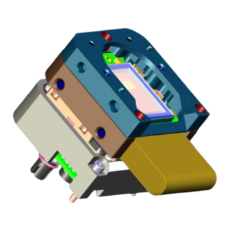
1. Lay wet wipes on the sensor, and wipe from one side to the other. 2. Wipe very gently, do not rub the surface. 4.3. Mounting the modules Figure 2, Mounting the Ranger-X3 modules Threaded mounting holes on the front module (M5) Precision mounting holes on the front module ... -
Page 9: Mounting The Connector Module
Laser Trig Out 2 (5V) – for strobing Internal 5V supply (max 100 mA) 8023182/1D7N/2021-09|SICK T E C H N I C A L I N F O R M A T I O N | R A N G E R - X 3... -
Page 10: Connecting The Integrated System
Never connect signal levels that exceed the input specification to the encoder inputs 8023182/1D7N/2021-09|SICK T E C H N I C A L I N F O R M A T I O N | R A N G E R - X 3... -
Page 11: Pin Assignment
Later firmware releases can give configurable 24V I/O options. 8023182/1D7N/2021-09|SICK T E C H N I C A L I N F O R M A T I O N | R A N G E R - X 3... -
Page 12: Gige Connector
GETH L2- GETH L3+ 8023182/1D7N/2021-09|SICK T E C H N I C A L I N F O R M A T I O N | R A N G E R - X 3 Subject to change without notice... -
Page 13: Service And Repair
Service and repair In case of unit failure, please contact SICK or the SICK representative that delivered the unit for further instructions. If you send the unit for service or repair, use the original transport protection. Interrupting or modifying the product will invalidate any warranty claims against SICK AG. -
Page 14: Technical Data
Measurement types 3D, Reflectance, Scatter Exposure modes Linear/HDR Performance Image sensor SICK CMoS with RoCC technology Sensor resolution 2560 px x 832 px 2560 px x 832 px 2048 px x 832 px Pixel size 6 μm × 6 μm 46.000 3D... - Page 15 –20 °C ... +70 °C, non-condensing temperature 8023182/1D7N/2021-09|SICK T E C H N I C A L I N F O R M A T I O N | R A N G E R - X 3 Subject to change without notice...
- Page 16 SICK AG | Waldkirch | Germany | www.sick.com...


Need help?
Do you have a question about the Ranger-X3 and is the answer not in the manual?
Questions and answers