
Related Manuals for Agilent Technologies 42941A


Summary of Contents for Agilent Technologies 42941A
- Page 1 Agilent 42941A Impedance Probe Kit Operation and Service Manual Third Edition Agilent Part No. 42941-90010 December 1999 Printed in: Japan...
- Page 2 In addition it violates safety standards of design, manufacture, and intended use of the instrument. The Agilent Technologies assumes no liability for the customer’s failure to comply with these requirements. 42941A comply with INSTALLATION CATEGORY Ι and POLLUTION NOTE DEGREE 2 in IEC 1010-1.
- Page 3 Because of the danger of introducing additional hazards, do not install substitute parts or perform unauthorized modifications to the instrument. Return the instrument to a Agilent Technologies Sales and Service Office for service and repair to ensure that safety features are maintained.
- Page 4 Instruments are warranted for a period of one year. Fixtures and adapters are warranted for a period of 90 days. During the warranty period, Agilent Technologies will, at its option, either repair or replace products that prove to be defective.
- Page 5 Assistance Product maintenance agreements and other customer assistance agreements are available for Agilent Technologies products. For any assistance, contact your nearest Agilent Technologies Sales and Service Office. Addresses are provided at the back of this manual. Safety Symbol General definitions of safety symbols used on the instrument or in manuals are listed below.
-
Page 7: Table Of Contents
Connecting the 42941A ........ - Page 8 Contents...
-
Page 9: Installation Guide
Installation Guide... -
Page 10: Incoming Inspection
Inspect the shipping container for damage. If the shipping container or cushioning material is damaged, it should be kept until the contents of the shipment have been checked for completeness and the 42941A has been checked mechanically and electrically. The shipment should contain everything listed in Table 1-1. If the contents are incomplete or if there is mechanical damage or defect, notify the nearest Agilent Technologies office. -
Page 11: Connecting The 42941A
Connecting the 42941A Follow the steps below to connect the 42941A to the 4294A. Step 1. Join the 42941A four-terminal pair connection block to the test connectors on the front panel of the 4294A by gently matching the four BNC connectors and securing screws of the block with the test connectors and accessory mounting holes of the instrument until they come into complete contact. -
Page 12: Serial Number
Serial Number Serial Number Agilent Technologies uses a two-part, ten-character serial number that is stamped on the serial number plate (Figure 1-2) attached to the bottom of the four-terminal pair connection block. The first four letters and one digit are the serial prefix and the last five digits are the suffix. -
Page 13: Overview
Overview... -
Page 14: Product Overview
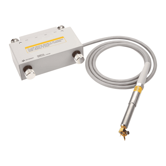
Product Overview Product Overview The 42941A is the impedance probe kit designed for the 4294A Precision Impedance Analyzer. When used with the 4294A, this kit allows impedance measurement and analysis in a wide frequency range of up to 110 MHz. Its 1.5-meter cable for probing allows you to evaluate implemented circuits and mounted devices. -
Page 15: Functions
Overview Functions Functions Figure 2-2 and Figure 2-3 show the names of the 42941A’s parts and probe adapters, respectively. Figure 2-2 42941A Parts Table 2-1 42941A Function NAME FUNCTION Four-terminal Pair Connects the 42941A to the 4294A Connection Block Securing Screws Secures the 42941A to the 4294A. - Page 16 Overview Functions Figure 2-3 Probe Adapters Table 2-2 Probe Adapters NAME FUNCTION 3.5-mm Short A short device used for the adapter setup. A load device (50 Ω ) used for the adapter setup. 3.5-mm Load Pin Probe Attached to the probe to measure implemented circuits, mounted devices, and printed circuit patterns.
-
Page 17: Operation
Operation This chapter describes the proper methods for setting up the 4294A, connecting the probe adapter, fixture compensation with the 42941A, and DUT measurement. -
Page 18: 4294A Setup
Never give any mechanical shock to the probe. Adapter Setup Connect the 42941A to the 4294A as shown in Figure 1-1 and perform the adapter setup described below. 1. More than 30 minutes warm-up time is required after turning on the 4294A. -
Page 19: Connecting Probe Adapter
Operation Connecting Probe Adapter Connecting Probe Adapter Probe adapters are furnished with the 42941A to measure DUTs of various shapes and characteristics. Attach the appropriate probe adapter for your DUT. Connecting Pin Probe Attach the pin probe to the 3.5-mm connector top of the probe and insert the pin. -
Page 20: Connecting Ground Lead
Operation Connecting Probe Adapter Connecting Ground Lead Remove the screw fixing the ground contact to detach the contact. Use the removed screw to attach the ground lead to the pin probe. Figure 3-2 Connecting Ground Lead Chapter 3... -
Page 21: Connecting Bnc Adapter
Operation Connecting Probe Adapter Connecting BNC Adapter Attach the BNC adapter to the 3.5-mm connector on top of the probe. Figure 3-3 Connecting BNC Adapter Connecting Clip Lead Attach the BNC adapter to the probe and then attach the clip lead to the adapter. Figure 3-4 Connecting Clip Lead Chapter 3... -
Page 22: Fixture Compensation
The following procedure is for measurement of the compensation data with the 42941A. Performing Fixture Compensation Attach the probe adapter to be used for your measurement and perform fixture compensation. - Page 23 Operation Fixture Compensation Press OPEN key to start the OPEN compensation data measurement. When the OPEN compensation data measurement is completed, the softkey label OPEN on OFF (if it is off) changes to OPEN ON off. Performing Short Compensation Figure 3-6 Use an Put the probe adapter into the SHORTed state as shown in appropriate device for shorting since no short device is supplied with the BNC...
-
Page 24: Dut Measurement
Operation DUT Measurement DUT Measurement Before performing DUT measurement, open and short compensation should be done as described in the previous sections. DUT Measurement Using Pin Probe When measuring implemented circuits, mounted devices, and printed circuit patterns, use the pin probe. Figure 3-7 DUT Measurement Using Pin Probe NOTE... - Page 25 Operation DUT Measurement appropriate DC-blocking capacitor to the probe. Figure 3-8 Adjusting Pin-to-GND Gap DUT Measurement Using Ground Lead Use the ground lead to ground the probe to a distant point(Figure 3-9). When you attach the ground lead to the pin probe, detach the ground contact (refer to Figure 3-2).
-
Page 26: Dut Measurement Using Bnc Adapter
Operation DUT Measurement DUT Measurement Using BNC Adapter The BNC adapter is used to measure I/O terminals or cables that have BNC connectors. It is also used as a mounting base for the alligator lead. Figure 3-10 DUT Measurement Using BNC Adapter DUT Measurement Using Clip Lead Use the clip lead to measure devices with leads that are large or mounted on the circuit board. -
Page 27: Specifications
Specifications This chapter provides specifications of the 42941A test fixture. -
Page 28: Specifications
Specifications Specifications Specifications Applicable Instruments 4294A Precision Impedance Analyzer Frequency 40 Hz to 110 MHz Maximum Voltage ± 42 V peak max. (AC+DC) 25 Ω (Nominal) DC coupled Output Impedance Operating temp. -20°C to +75°C (except four-terminal pair connection Environment block) 0°C to +55°C (four-terminal pair connection block) 15% to 95%RH ( @ wet bulb temp. -
Page 29: Service
Service This chapter provides information on servicing and proper maintenance. -
Page 30: Maintenance
Maintenance Maintenance An exploded view of the 42941A for parts identification is shown in Figure 5-1 and Figure 5-2. Do not disassemble any further than shown. Maintenance consists principally of cleaning contacts and replacing worn or damaged parts. Take special care when cleaning contacts. - Page 31 Service Maintenance Figure 5-1 Replaceable Parts (part 1 of 2) Chapter 5...
- Page 32 Service Maintenance Table 5-1 Replaceable Parts (part 1 of 2) Reference Part No. Qty. Description Designator 42941-60001 PROBE 42941-65001 CHASSIS 42941-24001 COVER 42941-24015 KNOB 42941-24013 CANTACT PROBE 42941-60002 CONTACT ASSY 0515-1718 SCR M4X12 0515-0914 SCR-MACH M3X0.5 42941-61602 RF CBL ASSY 1400-0719 CABLE TIE 0515-1718...
- Page 33 Service Maintenance Figure 5-2 Replaceable Parts (part 2 of 2) Chapter 5...
- Page 34 Service Maintenance Table 5-2 Replaceable Parts (part 2 of 2) Reference Part No. Qty. Description Designator 42941-00601 COVER TOP 42941-40002 BUSHING 1253-0476 ADPT BNC-SMB 3050-0067 WSHR-FL MTLC 3050-0789 WSHR-FL NM 42941-25002 SLEEVE 2950-0054 NUT-HEX-DBL-CHAM 2190-0054 WSHR-LK INTL T 0515-0914 SCR-MACH M3X0.5 16047-40002 INSULATOR 42942-25006...