Advertisement
Advertisement

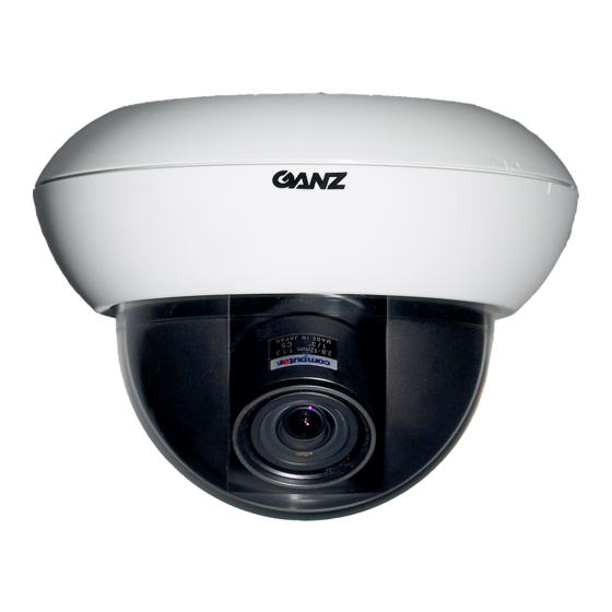
Summary of Contents for Ganz ZC-BNX4312NHA
-
Page 2: Table Of Contents
Thank you for your purchase of this product. Before operating the product, please read this instruction manual carefully to ensure proper use of the product. Please store this instruction manual in a safe place for future reference. CONTENTS PRODUCT FEATURES ... EG-2 SAFETY PRECAUTIONS ... -
Page 3: Parts Description
PARTS DESCRIPTION Exterior Surface mount cover Body cover Inner cover Coaxial video cable Camera body Accessories Service monitor cable Removing and attaching the cover Dome cover To remove : Pull the cover away. To attach : Insert the cover and push it gently until you hear a click. ... -
Page 4: Installation And Adjustment
INSTALLATION AND ADJUSTMENT Attaching the unit You can use the following three methods to attach the unit. Please use the method that best fits the conditions of the area in which you want to install the unit. Attaching to the surface of the ceiling or wall Use this method to attach the unit to the surface of the ceiling or wall. - Page 5 Attaching to the surface of the ceiling or wall This section explains how to install the unit where cables are running through the interior of the ceiling or wall. When running cables on the exterior surface of the ceiling or wall, please drill holes in the ceiling or wall as directed in step 1, then refer to “Running cables on the exterior surface of the ceiling or wall”...
- Page 6 Embedding in the ceiling or wall Be sure to use the adapter ring when embedding the unit in the ceiling or wall. Drilling holes in the ceiling or wall Use the template included to mark out the position on the ceiling or wall where you want to install the unit.
-
Page 7: Connecting The Cables
Connecting the cables Connect the power and video cables. Connect the video cable from the monitor and the coaxial video cable attached to the camera body. Connect the video cable from the monitor here. Connect the power cable. ... -
Page 8: Attaching Service Monitor
Attaching the service monitor Use the service monitor cable to check and adjust camera direction, focus, and angle on a service monitor. The service monitor is not supplied with this unit. Please have one ready. Adjusting the camera direction The camera body is set in a tri-axial mounting allowing movement in the pan, tilt, and rotational planes. - Page 9 Adjusting the view angle, focus and iris Move the lever to adjust focus and angle of view. Focus adjustment lever / View angle adjustment lever Attention When using the ZC-D5550NHA, adjust the focus when the dome cover ● in place so that the axis of the lens goes passes through the center of the dome cover, as in the illustration below.
- Page 10 Setting the D D/N (Digital Day/Night) switch This function digitally processes the image from the camera to provide a bright picture even in very low light conditions. Camera images are limited to black and white while this function is active. The camera will automatically begin providing color images again when the environmental light in the area where the camera is installed becomes brighter.
-
Page 11: Specifications
SPECIFICATIONS Model No. Focal length Max. aperture ratio Iris F1.0 - F360C (DC auto iris) Angle of view (Wide to Tele) TV system Scanning system Image sensor Effective elements Scanning frequency Video output Horizontal resolution Min. Illuminance 50IRE 1.25 lx (D D/N : OFF) / 0.83 lx (D D/N : ON) 30IRE 0.63 lx (D D/N : OFF) / 0.42 lx (D D/N : ON) S/N ratio... - Page 12 096-1.0...


Need help?
Do you have a question about the ZC-BNX4312NHA and is the answer not in the manual?
Questions and answers