Table of Contents
Advertisement
Advertisement
Table of Contents
Troubleshooting

Related Manuals for Waygate Technologies Everest Mentor Visual iQ VideoProbe


Summary of Contents for Waygate Technologies Everest Mentor Visual iQ VideoProbe
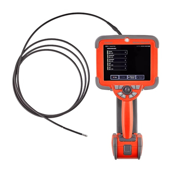
- Page 1 Everest Mentor Visual iQ VideoProbe Operating Manual MVIQAMANUAL Rev. N...
-
Page 2: Table Of Contents
Table of Contents Image & Video Setup ......................39 Introduction ............................4 Measurement & Annotation Setup ................40 About this Manual ........................4 Capturing and Adjusting Images ................41 Technical Support ........................4 Working with Video ......................54 System Overview ........................4 Standard Equipment ......................5 Measuring Features and Indications ..............55 Optional Features .........................5 Point Cloud View (3DPM and 3D Stereo) ............59 Safety Information ........................6... - Page 3 Table of Contents Appendix F. Environmental Compliance ............100 Appendix G. Regulatory Compliance ..............101 Appendix H. Creating a Personalized Logo File ........... 105 Appendix I. Open Source Software Availability ...........107 Appendix J. Restoring Factory Settings .............107 Appendix K. Updating MViQ Software .............. 108 Appendix L.
-
Page 4: Introduction
Introduction About this Manual This manual and the related equipment is intended for visual inspection technicians with a basic understanding of inspection principles and practices, and who are familiar with basic computer operations, but who may not have experience with a video borescope system. The manual contains safety, compliance, and basic operating and maintenance instructions for the VideoProbe™... -
Page 5: Standard Equipment
Standard Equipment MViQ AC Adapter/Battery Charger Safety and Essential Use Hard Copy 2-hour Li-Ion Battery Optical Tip Storage Case Quickstart Card MViQ Storage Case USB Thumbdrive Containing Documentation, including User's Manual Optional Features Belt Clip Keyboard (wired or wireless) Software: Inspection Manager Insertion Tube Gripper Optical Tips (OTA's) Upgrade either MViQ Inspect or Touch configurations with the purchase... -
Page 6: Safety Information
Safety Information Note: Before using or servicing the system, read and understand the following safety information. Symbols and Terms The following symbols appear on the product: See accompanying documentation. General Warnings The following warning statements apply to use of the system in general. Warning statements that apply specifically to particular procedures appear in the corresponding sections of the manual. - Page 7 Battery Warnings Only use the battery and power supply specified for use with the system. Before use, thoroughly review the instructions in this manual for the battery and battery charger to fully understand the information contained in them, and observe the instructions during use. WARNING •...
-
Page 8: Informations Sur La Sécurité
Informations sur la sécurité Remarque: avant l’utilisation ou l’entretien du système, vous devez lire et comprendre les informations de sécurité qui suivent. Symboles et termes employés Les symboles suivants sont apposés sur le produit: Voir la documentation jointe. Avertissements généraux Les avertissements suivants s’appliquent à... - Page 9 L’appareil comporte une batterie lithium ion et du magnésium à l’intérieur de son boîtier. En cas d’incendie de l’appareil, servez-vous d’un extincteur agréé pour une utilisation sur les incendies électriques et les métaux inflammables. En aucun cas, n’utilisez de l’eau. Avertissements liés à...
-
Page 10: Start Up
Start Up Hard Name Short Long Double Press Press Press Back Moves back one Moves to live Component Identification button (and screen image Power On) – LCD Touchscreen Save Quick save Save with Record a button (assigns default options Screenshot –... - Page 11 Touchscreen and Keys – Dual Control Systems you can drag with your finger to change the displayed view. – Select the Zoom function using either soft keys or the touch screen (all displayed Most functions can be accomplished using the touchscreen or with a combination soft-key bar items can be selected either with the corresponding soft key or by of key presses and joystick movements.
-
Page 12: Unpacking, Assembling, And Powering The Mviq
Unpacking, Assembling, and Powering the MViQ Unpacking and Putting Away the System (Small Case) Caution: If you do not pack the system carefully, as described, damage might occur. – The insertion tube (shown in red for clarity) is held in the case’s internal storage reel, which is accessed through the orange funnel shown here. -
Page 13: Unpacking And Putting Away The System (Large Case)
Unpacking and Putting Away the System (Large Case) Caution: If you do not pack the system carefully, as described, damage might occur. – Remove tray to access additional storage space. – The insertion tube (shown in red for clarity) is held in the case’s internal storage reel, which is accessed through the orange funnel shown here. Install the insertion tube before installing the probe-and-handset assembly and remove it after removing the probe-and-handset assembly. -
Page 14: About The Battery
About the Battery a two hour battery will take approximately two hours to charge. Charging time will be longer if the battery is connected to an operating MViQ system while charging. The MViQ is powered by a 10.8 V (nominal), 73 Wh, 6.8 Ah Lithium Ion battery. Note: All batteries are shipped with a partial charge. -
Page 15: Powering The Mviq On And Off
Supplying Power to the MViQ The MViQ is powered by a 10.8 V (nominal), 73 Wh, 6.8 Ah Lithium Ion battery. The battery is charged by connecting the power adaptor to the battery, then connecting the supplied AC-to-DC power adaptor to a suitable (100-240 VAC, 50-60 Hz, <1.5 A rms) AC power source. -
Page 16: Changing Probes And Ota's
Changing Probes and OTA's Attaching and Removing the Probe – Insert the pin at the base of the handset into the mating groove at the bottom of the probe. – Rotate the probe towards the back of the handset, applying enough pressure for the latching mechanism to “click.”... -
Page 17: Setting Up The Mviq Operating System
Setting Up the MViQ Operating System – Select the lower left corner of the display (which typically contains the on-screen Logo) or the hard key at any time to open or close the Global Menu, which provides access to several features including the Settings Menu. -
Page 18: Working With Profiles
Working with Profiles After entering a name and clicking Done, the new profile is added to the list of available profiles. This profile includes the global- menu settings in place, at the time of its creation, for each of the parameters listed below. Anytime A Profile defines several parameter settings. -
Page 19: System Setup
System Setup – Tap the on-screen Logo (or press the hard key) to open the Global Menu, then open the Settings Menu. – Select to alter the system-specific settings shown here. – This bar indicates that additional options are available. Drag your finger up or down anywhere on the screen to show additional options. - Page 20 Loading and Selecting the Operating Language Slider at maximum: Provides more precise steering control when the desired target is located from 45-180 degrees from the camera at its home – Choose from the operating Languages currently available for use. position. For inspections where the areas of interest are primarily looking Selecting Load allows you to upload a new version of any of the existing sideways or even backwards, this is a useful slider setting.
-
Page 21: Screen & Display Setup
Screen & Display Setup – Tap the on-screen Logo (or press the Menu hard key) to open the Global Menu, then open the Settings Menu. – Select to alter the display-screen appearance and operation. 3 – Select the display screen’s touch-sensitive control OFF or ON. Once turned OFF, the icon appears at the top of the display screen. - Page 22 – Select OFF or ON for the Record icon. When ON, the Record icon is displayed on the right side of the display. A short touch of the Record icon will begin recording video and the icon will reflect a Pause icon. Subsequent short touches toggles between Record &...
-
Page 23: Connectivity Setup
Connectivity Setup – Tap the on-screen Logo (or press the hard key) to open the Global Menu, then open the Settings Menu. – Select to work with settings that control the connection of the MViQ to WiFi networks and Bluetooth devices. –... - Page 24 – Enter the drive letter you wish to assign (in the MViQ’s File Manager) to the shared folder, then input the complete path to the folder on the network- connected PC. Following is an example of a complete path to insert in the Folder line: \\Device Name\TestShare Folder.
-
Page 25: Blade Counter Analytics
Waygate Technologies has developed the ability to detect, track and count specific “points of interest” such as aerofoil Leading or Trailing Edges. It can be even leveraged to count within scenes such as blade roots. It is not limited to gas-washed surfaces only. - Page 26 Warning: Analytic applications are intended to assist the user whilst performing in-situ visual inspections. Results will vary depending on your application and the method employed during setup. You, the user, are responsible for following the appropriate procedures and standards. Waygate Technologies cannot be held responsible for the accuracy and outcome of any inspections.
- Page 27 Activating / De-activating Blade Counter Enter MViQ Global Menu and select ‘Analytics’ 2. Accept disclaimer 3. Still Analytic’ page is now displayed. Select ‘Live Analytics’ softkey to view next page 4. Select ‘Blade Counter’ tile and toggle from ‘off’ to ‘on’ state 5.
- Page 28 Blade Counter Setup Adjust and position the probe to a suitable position as to conduct a visual inspection. The operation of the Blade Counter analytic requires the probe to remain stationary. Adjust the blade aerofoil to simulate entering the desired ‘tracking region.’ Entry Line The Entry Line is displayed as a blue line.
- Page 29 Press ‘next step’ softkey once complete. Limit Line & Trigger Point No adjustment of blade aerofoil is required within this step. The Limit Line is displayed as a yellow line. Adjust cursors and position line to coincide with both Entry and Exit Lines (Figure 3a and 3b). Fig 3a.
- Page 30 Verification Verification process is the opportunity to test the analytic with the assigned tracking region. It is best practice to rotate the engine to present at least three blade aerofoils through the tracking region to ensure successful operation during the actual visual examination. There is no upper limit to the number of blades to include during this step.
- Page 31 Press ‘Done’ softkey to launch Blade number textbox on screen Figure 8a. Blade Counter active showing blade number textbox. Figure 8b. Blade Counter active showing adjusted blade number textbox. The textbox can be moved to any location on screen. For example, if multiple blades are visible within the FoV, move its location to coincide with actual blade being counted (Figure 8b). Note: The analytic will pause when the borescope enters a different state e.g.
- Page 32 Failed Verification It is possible for the analytic to mis-count aerofoils during verification. Some or all blades may not be detected due to insufficient contrast between the blade edge and the background scene. Alternatively, the Blade Counter may trigger unexpectedly if other edges are detected within the tracking region. Because of this, it is important to press the ‘No’...
-
Page 33: Still Analytics
Still Analytics LM2500 assist-S Analytic Waygate Technologies has developed an ADR analytic based on Machine Learning. The analytic was trained using thousands of representative images from LM2500 inspections that have been characterized to teach a neural network about items or areas of interest. - Page 34 Using the LM2500 assist-S Analytic Freeze Frame Image Function can be accessed from the live video state by tapping the touchscreen or pressing ‘Enter’ on the handset. Once activated, “FF” will appear in the top left status bar. LM2500 assist-S analytic will now activate and analyze the image. “LM2500 assist-S …..” will now be visible in the top right hand corner of the screen to visually indicate its operation.
- Page 35 • Reject – to disagree and disregard inference • Edit classification – to alter the defect category to another pre-determined type • Hide / Show confidence value All the above functions are active within Freeze Frame and Recalled states. It is possible to adjust, amend or undo these adjustments at anytime once the image has been saved. Press ‘Toggle Page’...
- Page 36 Press Review Indications and reveal the four subsequent options: HIDE all inferences 2. APPROVE 3. REJECT 4. EDIT Approving an indication reveals a Green Tick “ ”...
- Page 37 Rejecting an indication reveals a Red Cross “ ” Pressing ‘Edit’ enables the User to alter the defect classification e.g. From ‘Tear’ to ‘Dent/Nick’.
- Page 38 Activate the Global Menu > Settings. Scroll to Analytics and toggle to Show Confidence. Subsequent inferences will now display Confidence Value as a percentage function.
-
Page 39: Table Of Contents Image & Video Setup
Image & Video Setup – Tap the on-screen Logo (or press ) to open the Global Menu, then open the Settings Menu. – Select to change Image and Video related settings and defaults. – Follow the procedure shown here to change either the Image Save Location or Video Save Location. These represent the two locations where quick-save images or videos are automatically stored. -
Page 40: Measurement & Annotation Setup
List options are not intended for general use. Deleting a tip through the Edit List option will permanently remove that tip’s calibration data requiring the probe and tip to be returned to an authorized Waygate Technologies service center for re-calibration. – Save Preset Annotation (notes) to an external storage device or Import preset notes to the instrument from an external device. -
Page 41: Capturing And Adjusting Images
Steer or Steer and Stay mode. In either mode, the bending neck articulates to follow the joystick motion. They differ in how they behave after the joystick is released (click here to learn how to setup the sensitivity of either mode). Steer mode allows the bending neck to drift towards a straight position when the joystick is released. - Page 42 Temperature Sensor Warnings When excessive temperature is detected, the applicable icon displays in the status bar, and one of the warning messages listed below appears across the top of the display screen: • Probe tip temperature has entered the WARNING Zone—this message displays in an orange banner when tip temperature exceeds approximately 95°C and appears in the status bar.
- Page 43 Freezing the Image Freeze an image to temporarily capture it for review or adjustment. Moving the joystick in a frozen view does not articulate the probe tip. – Briefly press either of these keys or tap anywhere on a live on-screen image to freeze the display.
- Page 44 Selecting a View When an image is frozen, the user can select from various Views as described below. – Anytime an image is frozen, select to choose from all available View options. – Displays a Normal dynamic range image created by applying Adaptive Noise Reduction (ANR) processing to live video frames prior to the freeze request.
- Page 45 Note: Screenshots are BMP image files of the display screen, do not contain RVI data of any type, are stored in an automatically created subfolder titled “Screenshots,” and are assigned the auto-generated image file name but identified with the addition of the letters “ss.” Note: The DVD drive may not serve as either the default or alternative saving location.
- Page 46 Working with a Recalled Image Image and video files can be stored in the MViQ or a detachable device. The Recall feature allows these stored files to be displayed, measured, and annotated. Follow these steps to locate and Recall a stored file: –...
- Page 47 Zoom to Magnify The Zoom feature magnifies the view of live, frozen, and recalled images. Because the zooming process is digital, pixilation increases as the image is magnified. Note: MViQ offers two equivalent zooming methods. – Select this soft key to launch the Zoom control bar. –...
- Page 48 Image Transformation Settings These settings, accessed by selecting the Image Menu, alter the appearance of live images. (Some of these settings also affect frozen or recalled images.) At any time, the values assigned to these twelve transformation settings can be saved as a user-named Preset.
- Page 49 – Tap to turn Distortion Correction either ON or OFF. The Distortion – Tap to turn the Single View feature ON or OFF. Single View is useful while Correction function corrects the wide-angle barrel distortion that occurs positioning a stereo optical tip. This feature makes it easier to navigate the when using optical OTA's with various angle fields of view camera by temporarily eliminating the second image.
- Page 50 Working with Preset Image Transformation Settings Values assigned to the image transformation settings can be saved as a user-named Preset. When recalled, all transformation settings will revert to the values assigned when the Preset was created. Each user-named Preset appears as a soft key in the Image Menu. To load a Preset, simply select its soft key or press the corresponding button.
- Page 51 Working with a Split Screen A split screen displays two images side-by-side in any combination of live, frozen, or recalled. Since half-screen still images are cropped, dragging a finger across the display or moving the joystick allows you to pan side- to-side within the image.
- Page 52 Annotating with Text and Arrows Annotating an image means adding text or arrows to point out areas of interest: cracks, indications, etc. You can annotate live, frozen, and recalled images. – Select Annotation to launch the feature. – Tap to switch between the Soft Key Bar’s top and bottom row. Double tapping in this location hides or displays the soft keys and status bar.
- Page 53 Adding Audio Notes to an Image During the process of saving an image, audio notes can be added provided a microphone is first attached to the MViQ. The audio file will be named with the same name as the image + .mp4. –...
-
Page 54: Working With Video
Recording Live Video – Tap the lower-left corner of the display (typically contains a Logo) at any time to open the Global Menu, which provides access to the video Record button. Upper trigger can also be customized as Video Record button, through Global Menu >... -
Page 55: Measuring Features And Indications
3D Phase Measurements (3DPM) or stereo measurements, the image must be captured using a 3DPM, or stereo tip. All saved measurement images can be re-measured on a PC using Inspection Manager software from Waygate Technologies. For details, call your local sales representative. - Page 56 Measurement Types Stereo Over comparison measurements: The system may be unable to position • More accurate. the matching cursors accurately The MViQ system supports four types of measurement: 3D Phase, • No known reference is needed. with any of these conditions in the 3D Stereo,Stereo, and Comparison.
- Page 57 3D Measurement Types and Special Capabilities This section specifically addresses cursor placement for each type of 3D Phase and 3D Stereo Measurement. Length Point-to-line Depth Depth Profile Description: Linear Description: The perpendicular Description: The perpendicular Description: Depth of isolated corrosion distance between a surface and a point (Point-to-Point) measurement distance from a point to a line.
- Page 58 Area Blade Tip Clearance Multi-Segment Area Depth Description: The surface area Description: Automatically Description: The length of a Description: Gives a depth contained within multiple identifies the blade and profile through the deepest or nonlinear feature or defect. cursors placed around a feature or shroud, and maps the edge of the highest point in an area of interest.
-
Page 59: Point Cloud View (3Dpm And 3D Stereo)
Point Cloud View (3DPM and 3D Stereo) The point cloud view offers the following advantages: • Helps the user visualize the measurement to ensure proper cursor placement and verify 3D data quality. • Shows location of high and low points to help profile and depth cursor positioning. - Page 60 Measurement Plane (3D Phase and 3D Stereo) A Measurement Plane is not a standalone measurement type and gives no result. When used with specific measurement types, the Measurement Plane allows cursor placement in red areas where no 3D data is present or where noise in the 3D data may reduce measurement accuracy. Once placed, a Measurement Plane establishes a 3D plane aligned with a flat area on the surface of the viewed object.
- Page 61 Placing a Measurement Plane (3D Phase and 3D Stereo) A measurement plane extends an object beyond its existing edges (like the surface of a broken compressor blade). This allows placement of measurement cursors within an area that does not include measurable image pixels.
- Page 62 Measurement Plane Warnings (Edge View Angle) When using a Measurement Plane with Point to Line, Area, or Depth to measure near an edge, the viewing perspective can affect accuracy, especially if the edge has a significant radius. To help the user maximize accuracy, the system displays an Edge View Angle (EVA) value ( ) next to the MTD and an Edge View Angle Line (EVA Line) (...
-
Page 63: Phase Measurements (3Dpm)
3D Phase Measurements (3DPM) 3D Phase Measurement OTA's include an LED based structured light projection system that allows the MViQ to produce a three-dimensional surface scan of the object. Measurements are then made directly on the surface and displayed on the image. Preliminary steps of matching cursors or marking shadow lines are not necessary. Maximum Target Distance - MTD Number The 3D Phase Measurement system will display a number on-screen after a measurement is complete. - Page 64 3D Phase Measurement Procedure – When the target is in position, select the soft key (or long hold ). The 3D Phase Measurement scan will begin. Note: Keep the probe still during the PM surface scan, typically 1 second. Multiple images are taken to complete the scan, and the probe must be held still during this sequence.
- Page 65 Making 3DPM Measurements (Depth Profile Example) Note: While the following procedure applies specifically to a Depth Profile measurement, refer to this procedure and the information in the section titled Types of 3D Measurement to conduct any type of 3DPM. – To create a Depth Profile measurement, place the first and second cursors on a flat surface on opposite sides of the area of interest. This procedure is described in a following section.
-
Page 66: 3D Stereo Measurements
3D Stereo Measurements Stereo measurements require the use of StereoProbe measurement OTA's to capture stereoscopic images of a target. 3D Stereo and Stereo both utilize the same Stereo OTA's, which provide two images of the same scene from slightly different perspectives. They both rely on triangulation and the matching of surface points in both images to determine 3D coordinates used for measurement. - Page 67 3D Stereo Measurement Procedure, Part 1 Prior to collecting 3D Stereo measurements, a calibrated 3D Stereo OTA must be attached to your MViQ. Properly position the tip for measurement (click here to see how to position the tip), which may be aided by temporarily displaying a single image by turning Single View mode ON (click here to select Single View).
- Page 68 3D Stereo Measurement Procedure, Part 2 – Patented Zoom Window allows for precise positioning of the active cursor. Tap the window's edges (or move the cursor with the joystick) to adjust the active cursor position. (Click here to learn about turning the Zoom Window on or off and other Measurement Settings). –...
- Page 69 Making 3D Stereo Measurements (Depth Profile Example) Note: While the following applies to a Depth Profile measurement, refer to this procedure and the section titled Types of 3D Measurement for other types. – To create a Depth Profile measurement, place the first and second cursors on flat surfaces on the same plane on opposite sides of the area of interest.
- Page 70 Stereo Measurements and right of each cursor to accurately place the matching cursors in horizontal relationship to the left-side cursors. Stereo measurements require the use of StereoProbe measurement OTA's to capture stereoscopic images of a target — two pictures of the same target from two different angles.
- Page 71 About the Matching Cursors For each cursor you place on the left image during stereo measurement, the system places a matching cursor on the right image for use in triangulation. You must place each left cursor on an image point (a pixel) that has sufficient surrounding detail to differentiate it from its neighboring pixels.
- Page 72 Stereo Mode Measurement Procedure, Part 1 Prior to collecting stereo measurements, a calibrated stereo optical tip must be attached to your MViQ. Properly position the tip for measurement (click here to see how to position the tip), which may be aided by temporarily displaying a single image by turning Single View mode ON (click here to select Single View and learn about other Image Transformation settings).
- Page 73 Stereo Mode Measurement Procedure, Part 2 – Tap the screen (or hit ) to display the second cursor. Position it as described in items 5 and 6. Note: Generally, you get the best results by leaving the matching cursors exactly where the system places them. However, under certain circumstances, such as when a repeating pattern exists, you may need to help the system find the correct match.
- Page 74 Features of the Stereo Measurement Screen – The currently active cursor appears larger than all others. Note that this cursor’s position can be altered by the joystick or by dragging it across the screen. – Tap any on-screen dimension to select it for repositioning (by dragging or with joystick) –...
- Page 75 Stereo Measurement Types This section specifically addresses cursor placement for each type of stereo measurement. Description: Description: Description: Description: Description: Linear (Point-to- The perpendicular The perpendicular The surface The length of a Point) distance from a distance between a area contained nonlinear feature or point to a line surface and a point...
-
Page 76: Comparison Measurements
Comparison Measurements Comparison measurements rely on the known dimensions of an object that has been set in the field of view either by the manufacturer or by the probe or takes advantage of known dimensions within the frozen image. The MViQ processor uses these known dimensions as a reference scale for measuring an unknown target. -
Page 77: Troubleshooting Measurements
Troubleshooting Measurements 3D Phase, 3D Stereo, or Stereo Measurements • Move the probe tip as close as possible to the target, maximizing magnification. • Verify that the OTA len is clean and is threaded on to the probe head securely. •... -
Page 78: Managing Files
Managing Files Working with Removable Storage Devices One or more USB storage devices can be connected to the iQ, accessed through File Manager, written to and copied from, and Ejected using the features described here. The optional DVD drive may not serve as either the default or alternative saving location. -
Page 79: Editing Files And Folders/Creating Folders
Editing Files and Folders/Creating Folders Image and video files can be stored in MViQ or a detachable device. The File Manager feature allows these stored files (or the folders in which they are stored) to be Copied, Cut, Pasted, Deleted, Renamed, or Created (in the case of folders). -
Page 80: Mdi
Loading and Unloading Menu Directed Inspections Follow this process to load or unload a Menu Directed Inspection. Note: MDI inspection files have the file extension of .mdz. A maximum of fifty MDI inspection files may be loaded at any given time. –... - Page 81 Entering Asset, Inspector, & Location Data At the start of an MDI inspection, users are prompted to enter the Inspection Details and to select the directory (folder) into which your inspection results will be saved. – Inspection Details information (varies for each MDI) is entered at the start of an inspection.
- Page 82 Selecting an Inspection Point At this time, you can navigate through the inspection levels until you have reached the desired inspection point. – Displays the MDI folder name.. – Select branches by touching or using the joystick to navigate to the inspection’s next-lowest navigation level.
- Page 83 MDI Branch Information Flagged Image Contained in Branch 1 - If an image in a branch has been flagged, the vertical bar next to that branch is colored red Approving a Full MDI Branch 2 - A long press inside the rectangular tile in the MDI menu will cause a check-mark to appear.
- Page 84 Saving an Image or Video in an MDI Inspection 1. To save an image in the selected inspection point, press the SAVE hard key. Double pressing this key saves a screenshot of the display screen. During the save process, some of the following are available: Required Observations - IIf required by the MDI being run, a drop-down characterization list (6) appears before the save menu.
- Page 85 Viewing Reference Material – Select at any level within the inspection to access Reference Material associated with the level or point – Select any PDF, image, or video material to open and view on the MViQ display – Select Show All to access all Reference Material associated with the active inspection, which may be more than the material associated with the active level.
- Page 86 Generating an MDI Report Follow this process to generate an MDI report. – Select to Generate a Report and, if no inspection is active, choose the desired inspection. – After selecting the inspection for which you wish to generate a report, choose Done.
- Page 87 Customizing an MDI Report Customize an inspection report by specifying the following parameters: REPORT OPTIONS: • Report Name – Override the automatic inspection report file name. • Report Format – Choose the version of MS Word in which to publish. •...
-
Page 88: Maintenance And Troubleshooting
70% alcohol-to- If you discover conditions that require evaluation or repair, return the system water solution. to Waygate Technologies. Early repair of minor conditions can prevent much more costly repair. Inspecting and Cleaning the Handset Caution: Do not immerse or soak the handset or the probe power plug. -
Page 89: Troubleshooting Guide
Image quality is Various • If available connect a different probe to handset. otherwise poor. • If image quality issue is associated with a specific probe contact Waygate Technologies to obtain a return material authorization (RMA). No image appears in Various •... - Page 90 • Insertion tube is stuck. • Gently push the insertion tube in and out with a slight twisting motion in order to free the probe. If probe not freely withdraw cannot be freed contact Waygate Technologies Tech Support. from the storage reel. Handset...
- Page 91 • Contact Waygate Technologies for a replacement charger. • Defective Battery • Try another battery. • If replacement battery does not restore operation contact Waygate Technologies to obtain a return material authorization (RMA). System runs when connected to • Verify correct battery is •...
-
Page 93: Appendices
APPENDICES Appendix A. Technical Specifications Operating Temperature -25ºC to 100ºC (-13ºF to 212ºF). Reduced articulation below 0ºC (32ºF) System -25º to 46ºC (-13ºF to 115ºF). LCD may require warm-up period below 0ºC (32ºF). Storage Temperature -25º to 60ºC (-13ºF to 140ºF) Relative Humidity 95% max, non-condensing Waterproof... - Page 94 Data I/O Ports Two USB 3.0 host ‘A’ ports, one USB 3.0 client micro ‘B’ port, Video Out DisplayPort Brightness Control Auto and Variable Illumination Type White LED Long Exposure Auto - up to 16 seconds White Balance Factory default or user defined Wi-Fi Adapter 802.11a/b/g/n, 2x2 Bluetooth Adapter...
- Page 95 Software Operating System Embedded, multi-tasking operating system User Interface Menu-driven and soft button operation; menu navigation using either touchscreen or joystick File Manager Embedded file manager supports the following operation on files and folders: copy, cut, create, rename, delete, filter and sort. USB and internal flash storage.
-
Page 96: Appendix B. Optical Tip Table
Appendix B. Optical Tip Table... -
Page 97: Appendix C. Chemical Compatibility
• Water • Aircraft Gasoline • Jet-A-Fuel • Isopropyl alcohol • JP-4 Fuel • assume for Waygate Technologies any other liability in connection with the sale of its VideoProbe products. Waygate Technologies shall not be Kerosene liable for any loss or damages, whether direct or indirect, incidental, or •... - Page 98 Appendix E. Verifying Measurement OTA's Verify measurement OTA's each time you use them to ensure that no mechanical damage has degraded their accuracy. MViQ systems are shipped with a measurement verification block. This tool lets you verify the accuracy of measurement OTA's. It contains optical measurement targets whose accuracy is traceable to the United States National Institute of Standards and Technology (NIST) measurement standards.
- Page 99 Note: When verifying legacy stereo measurements using a blue side stereo tip in a VER2600E block, an orange box will flash around the INDEX if below minimum set value. – Perform manual length measurements between the crosshairs. With accurate cursor placement, a measurement tip of any type in good condition should give results of 0.100 ± 0.005 inches (1.00 ± 0.05 mm). If your measurement does not fall within these limits, try the suggestions under Troubleshooting Measurements.
-
Page 100: Appendix F. Environmental Compliance
Appendix F. Environmental Compliance The equipment purchased has required the extraction and use of natural resources for its production. It may contain hazardous substances that could impact health and the environment. In order to avoid the dissemination of those substances in the environment and to diminish the pressure on the natural resources, we advise the use of appropriate take-back systems. -
Page 101: Appendix G. Regulatory Compliance
Appendix G. Regulatory Compliance To access regional regulation certification information, please access internal instrument memory D:\Notices\MVIQ_Regulatory_Certifications.pdf European Community — CE Notice: mark indicates compliance with the essential requirements of Directive EU RED (2014/53/EU). Such marking is indicative that this equipment meets or exceeds the following technical standards: EN 300 328 EN 301 893... - Page 102 FCC Compliance Statement: This device complies with part 15 of the FCC Rules. Operation is subject to the following two conditions: 1) This device may not cause harmful interference and 2) This device must accept any interference received, including interference that may cause undesired operation. Note: This equipment has been tested and found to comply with the limits for a Class B digital device, pursuant to part 15 of the FCC Rules.
- Page 103 Complies with the Canadian ICES-003 Class B specifications. Cet appareil numérique de la classe B est conforme à la norme NMB-003 du Canada. IMPORTANT NOTE: IC Radiation Exposure Statement: This equipment complies with IC radiation exposure limits set forth for an uncontrolled environment. The transmitter module may not be co-located with any other transmitter or antenna.
- Page 104 Brazil Wireless Statement: Este equipamento opera em caráter secundário, isto é, não tem direito a proteção contra interferência prejudicial, mesmo de estações do mesmo tipo, e não pode causar interferência a sistemas operando em caráter primário. (This equipment operates on a secondary basis, ie, not entitled to protection against harmful interference, even of the same type stations, and cannot cause interference to systems operating on a primary basis.) South Korea Wireless Statement: (EMC registration is done on this equipment for a business use only (Class A).
-
Page 105: Appendix H. Creating A Personalized Logo File
Appendix H. Creating a Personalized Logo File A custom logo can be loaded into the display, where it will appear in the lower left corner (in place of the default Logo). Suitable logos must be saved as PNG file format and must be no larger than 140 by 140 pixels. It is advisable to use image files that are approximatley square. To replace the Waygate icon with a custom icon: –... - Page 106 To incorporate a transparent customized logo, you must first save the – Choose a single color. logo file in Photoshop, Gimp 2, or a similar graphics package capable of creating transparencies. If working in Gimp 2, follow the process below –...
-
Page 107: Appendix I. Open Source Software Availability
Appendix I. Open Source Software Availability There are various open source software packages that have been utilized within this product, and to meet license and copyright obligations, a copy of the source code for each package is available upon request, along with the individual licenses and copyright notices for each, for three years from the date of original installation upon the product. -
Page 108: Appendix K. Updating Mviq Software
Appendix K. Updating MViQ Software Software updating requires a connected USB drive or an Internet connection. The updating process must be carried out while the iQ is connected to an AC power source. – Tap the logo at the lower left corner of the screen or press to open the Global Menu, select the Settings Menu, then choose Software Update. -
Page 109: Appendix L. Longsteer™ Specifications
Appendix L. LongSteer™ Specifications Supply pressure: 100 – 150 PSIG Do not exceed supply pressure of 150 PSIG Dry air must be provided by the user. To get full articulation, insertion tube must be extended at least 10 feet off the reel. User is able to continue to inspect and steer while removing the probe from the reel. -
Page 110: Appendix M. Inspectionworks Connect (Iwc)
Appendix M. InspectionWorks Connect (IWC) Optional Collaboration Capability InspectionWorks Connect is an Internet service that enables video collaboration between Inspectors and remotely located Experts. Inspectors control their MViQ while simultaneously connecting through the IWC cloud infrastructure to a remote Expert via the IWC web portal. This allows the Inspector and Expert to share inspection video, exchange chat messages, and make on-screen annotations (circles, text, arrows or freehand drawings), which are seen by both participants. - Page 111 Note: If your device has already been equipped with IWC capability, the Start Session screen will display and you can begin an IWC session. – Select and enter the required information to begin a 30-day trial session or contact Waygate Technologies (see information above) to purchase the IWC capability.
- Page 112 Starting and Stopping an IWC Session InspectionWorks Connect is an Internet service that enables video collaboration between an Inspector and a remotely located Expert. Inspectors control their MViQ, sharing inspection video, exchanging chat messages, and making on-screen annotations seen by both participants. InspectionWorks Connect is an optional feature enabled at the time your device is purchased or acquired after device delivery.
- Page 113 Emailing an Invitation to Join an IWC Session and Expert Login – Select Invite to specify the email address of an Expert to whom you wish to automatically deliver the session URL, identification, and password. – Input the Expert’s email address and select Send. All required login information and a link to the IWC website will be automatically included in the email. –...
- Page 114 IWC Controls on the MViQ Inspector’s Screen – This icon appears on the MViQ display when an Expert joins the session. Whether or not the displayed image is shared, this icon is displayed whenever an Expert is logged into the session. –...
-
Page 115: Appendix N. Inspectionworks Insight
Appendix N. InspectionWorks Insight InspectionWorks Insight makes it easy to securely store, share and manage all your inspection and maintenance data. Upload and manage files directly from your device or through our web-based application. Insight provides tools to organize inspection data, search/filter on key attributes, analyze, create customer reports and share content with others. -
Page 116: Appendix P. Controlling The Mviq With An Ios Or Android Device
Appendix P. Controlling the MViQ with an iOS or Android Device Note: Connecting a device running iOS 8 or above to the MViQ allows users to control the system from a distance. iOS Streaming and Control Prior to being able to use an iOS device for streaming and controlling the MViQ system UI, iTunes will need to be installed on the system. Below are the steps to do so: 1. -
Page 117: Appendix Q - Mviq Eirp Values
Appendix Q - MViQ EIRP Values 802.11b Measured Power (dBm) Output Power (dBm) EIRP (dBm) Limit (dBm) 2412 MHz Normal 14.77 15.57 18.07 20.00 2442 MHz Normal 14.18 14.98 14.98 20.00 2437 MHz Normal 14.37 15.17 15.17 20.00 802.11g Measured Power (dBm) Output Power (dBm) EIRP (dBm) Limit (dBm) - Page 118 Measured Power Chain 0 (dBm) Measured Power Chain 1 (dBm) Output Power (dBm) EIRP (dBm) 2412 MHz Normal 9.24 9.23 13.37 15.87 2442 MHz Normal 11.08 11.27 15.31 17.81 2472 MHz Normal 10.54 10.76 14.78 17.28 802.11n HT40 Measured Power Chain 0 (dBm) Measured Power Chain 1 (dBm) Output Power (dBm) EIRP (dBm) 2422 MHz...
- Page 119 0.95 VHT0 - 80 MHz wide 17.8 0.72 VHT9 - 80 MHz wide 19.5 5470 MHz to 5725 MHz Transmitter power (dBm EIRP) Antenna Duty cycle Modulation Lowest channel Middle channel 0.99 6 Mb OFDM 20.0 20.6 0.92 54 Mb OFDM 19.8 20.6 0.99...
-
Page 120: Appendix R - Lithium Ion Battery Care
Appendix R - Lithium Ion Battery Care Store & Charge your batteries at room temperature • The worst thing that can happen to a lithium-ion battery is to have a full charge and be subjected to elevated temperatures. • Charge batteries at room temperature. Allow partial discharges and avoid full ones •... -
Page 121: Index
Index Symbols DVD reader/recorder 61 3D Measurement Handbook 98 3D Measurement Types 41 Edge View Angle 25, 45 3D Phase Measurement 46, 49 Edge View Angle Line 45 3DPM 46 Editing Files 62 3D Stereo Measurements 49 Environmental Compliance 81 EVA Line 45 AC-to-DC power adaptor 15 Adaptive Noise Reduction (ANR) 33... - Page 122 Keyboard 97 Quick Save 29 Known Networks 22 Range Finder 25 Large Case 13 Recalled Image 30 Logo 19, 86 Recalled Video 38 Long Exposure 33 Recording Live Video 38 LongSteer 90 Reference Dimension 59 Regulatory Compliance 82 Removing the Battery 14 Magnify 31 Rename 29 Maintenance 70...
- Page 123 Touchscreen 11 touch-sensitive control 21 Troubleshooting Guide 72 Troubleshooting Measurements 60 Updating MViQ Software 89 USB Slave Mode 23 USB Storage Device 61 Verifying Measurement Tips 80 video 38 video recording format 24 Video Save Location 24 View 28 Virtual Keyboard 18 Warranty 79 White Balance 24 WiFi 22...
-
Page 124: Customer Support Centers
Customer Support Centers China Baker Hughes Sensing & Inspection Co., Ltd. No. 8 Xi hu Road, Wu jin high-tech zone Changzhou, Jiang Su 213164 Waygate Technologies, LP China 721 Visions Drive Tel: + 86 400 818 1099 Skaneateles, NY 13152...
Need help?
Do you have a question about the Everest Mentor Visual iQ VideoProbe and is the answer not in the manual?
Questions and answers