Table of Contents
Advertisement
Advertisement
Table of Contents

Related Manuals for Waygate Technologies Krautkramer USM Go


Summary of Contents for Waygate Technologies Krautkramer USM Go
- Page 1 Krautkrämer USM Go / USM Go+ Operating Manual Id. No. 49 155 Rev. 10 (06/2021)
- Page 2 This Rev. 10 (06/2021) applies to the following software versions: USM Go: 2.08 (March 6, 2013) USM Go+: 2.08 (May 28, 2013) You will find the software version and the serial number of your instrument on the second operating level (CONFIG2 - ABOUT) ©...
- Page 3 First operating level (Base) To change between the first and the second operating level: USM Go: Press the joystick for 2 seconds. USM Go+: Press the center key of the keypad for 2 seconds. USM Go Rev. 10 (06/2021)
-
Page 4: First Operating Level (Options)
First operating level (Options) To change between the first and the second operating level: USM Go: Press the joystick for 2 seconds. USM Go+: Press the center key of the keypad for 2 seconds. Rev. 10 (06/2021) USM Go... -
Page 5: Second Operating Level
Second operating level USM Go Rev. 10 (06/2021) -
Page 6: Second Operating Level (Continued)
Second operating level (continued) Rev. 10 (06/2021) USM Go... -
Page 7: Status Display Icons
Status display icons Icon Meaning Icon Meaning SD memory card is inserted, Angle-beam probe 30° … 90°, flat surface, flashes when the SD card is accessed Reflection from the backwall Freeze active (Freeze), Angle-beam probe 30°, curved surface, Display is „frozen“. Reflection from the inner surface of tube Magnify gate is active Angle-beam probe 80°, curved surface,... -
Page 8: Power Level Indicators
Power level indicators Keypad functions Icon Meaning USM Go USM Go+ Battery charge level, remaining operating time in hours (approximate value) Charger/power adapter is connected, percentage of battery charge level (approximate value) Warning: Low battery charge level, remaining operating time in minutes (approximate value) Increasing the gain level in increments Decreasing the gain level in increments... -
Page 9: Navigation Using Joystick (Usm Go) Or Keypad (Usm Go+)
Navigation using joystick (USM Go) or keypad (USM Go+) USM Go USM Go+ Function Navigation between function groups, adjusting values Navigation within a function group, adjusting values Changing between operating levels (press for 2 seconds) USM Go Rev. 10 (06/2021) - Page 10 0-10 Rev. 10 (06/2021) USM Go...
-
Page 11: Table Of Contents
Contents Overviews 1.2 Important information on ultrasonic testing ....1-3 First operating level (Base)... . 0-3 Prerequisites for testing with First operating level (Options). - Page 12 Contents 1.6 Layout and presentation in 3.3 Connecting a probe ....3-9 this manual ..... . 1-13 3.4 Inserting the SD memory card .
- Page 13 Contents 4.3 Navigation and function keys ..4-7 Setting the brightness ....4-18 Navigation......4-7 4.7 Saving the settings .
- Page 14 Contents 5.5 Setting the pulser A-THRESHOLD/B-THRESHOLD (function group PULSER)... 5-14 (response and measurement threshold of the gate) ....5-24 VOLTAGE (pulser voltage) .
- Page 15 Contents 5.11 Rating of welds MAGNIFY GATE (spanning the gate). . . 5-65 (function group AWS D1.1) ..5-41 Activating the magnify gate function ..5-66 Rating of welds according to AWS D1.1. 5-42 Automatic A-scan freeze (Freeze) .
- Page 16 Contents Calibration reminder ....5-86 Turning the JISDAC evaluation off ..5-106 Password protection ....5-87 Deleting the DAC curve.
- Page 17 Contents Starting the echo height evaluation Storing the A-scan and parameters according to DGS ....5-123 in the test report ....6-9 Basic settings for the 6.2 Storing memos .
- Page 18 Deleting readings ....6-27 Service interface (Mini RS232-C) ..8-3 A-scan preview ....6-28 8.2 Peripherals.
- Page 19 Contents 10 Specifications 10.1 Specifications of USM Go and USM Go+ ... . . 10-2 Display screen ....10-2 Display .
- Page 20 0-10 Rev. 10 (06/2021) USM Go...
-
Page 21: Introduction
Introduction USM Go Rev. 10 (06/2021) -
Page 22: Safety Information
If you have any questions about the use of your test teries or with the charger/power adapter. The charger/ equipment, please contact your nearest representative power adapter meets the requirements of electrical of Waygate Technologies. safety class II. Rev. 10 (06/2021) USM Go... -
Page 23: Defects/Errors And Exceptional Stresses
Safety information 1 Introduction Defects/errors and exceptional stresses FCC compliance If you have reason to believe that a safe operation of This device complies with part 15 of the FCC Rules. Op- your USM Go is no longer possible, you have to discon- eration is subject to the following two conditions: nect the instrument and secure it against unintentional This device may not cause harmful interference. -
Page 24: Important Information On
1 Introduction Important information on ultrasonic testing 1.2 Important information on Operator training ultrasonic testing The operation of an ultrasonic test device requires prop- er training in ultrasonic test methods. Please read the following information before using your Proper training comprises for example adequate knowl- USM Go. -
Page 25: Technical Test Requirements
Waygate Technologies regularly holds specialized train- Ultrasonic wall thickness measurement ing courses in the field of ultrasonic testing. The sched-... -
Page 26: Effect Of The Test Object Material
1 Introduction Important information on ultrasonic testing Effect of temperature variations of importance for high-precision measurements. In oth- er materials, e.g. nonferrous metals or plastics, the The sound velocity within the test object also varies as sound velocity variations may be even larger and thus a function of the material's temperature. -
Page 27: Ultrasonic Evaluation Of Flaws
Important information on ultrasonic testing 1 Introduction Ultrasonic evaluation of flaws Echo display comparison method In present-day test practice, there are basically two dif- The echo from a small, natural flaw is usually smaller ferent methods of flaw evaluation: than the echo from an artificial comparison flaw, e.g. cir- cular disc flaw of the same size. - Page 28 1 Introduction Important information on ultrasonic testing The ultrasonic wave is attenuated in any material. This sound attenuation is very low, e.g. in parts made of fine- grained steel, likewise in many small parts made of oth- er materials. However, if the sound wave travels larger distances through the material, a high cumulative sound attenuation can result, even with small attenuation coef- ficients.
-
Page 29: The Usm Go
The USM Go 1 Introduction 1.3 The USM Go Rail inspection ● High PRF (up to 2000 Hz) The USM Go is a lightweight and compact ultrasonic ● Lightweight: 850 g (1.87 lb) flaw detector which is especially suitable ● Small and ergonomic ●... -
Page 30: Instrument Versions Usm Go And Usm
1 Introduction The USM Go Instrument versions USM Go and USM Go+ A joystick is used in the USM Go for navigation, for These functions are carried out by means of five keys in changing settings, and for selecting adjustment values. the keypad of the USM Go+. -
Page 31: Options
The USM Go 1 Introduction Options USM Go DGS ● DGS amplitude evaluation according to EN ISO Various options extend the basic functions of the USM 11666 Go and can be enabled by a code in each case. USM Go with an on-board data logger USM Go Base ●... -
Page 32: Special Features Of The Usm Go
1 Introduction The USM Go Special features of the USM Go ● easily perceptible reflection geometry when using an- gle-beam probes due to changing A-scan or back- ● small, lightweight, rugged ground color at every reflection point ● dust-tight and waterproof housing according to IP67 ●... -
Page 33: The Dms Go
The DMS Go 1 Introduction 1.4 The DMS Go 1.5 How to use this manual The USM Go uses the same operating principle as the This operating manual applies to all instrument versions portable thickness gauge DMS Go. of the USM Go. Any differences in the functions or ad- justment values are marked in each case. -
Page 34: Layout And Presentation In
1 Introduction Layout and presentation in this manual 1.6 Layout and presentation in this Listings manual Listings are presented in the following form: ● Variant A To make it easier for you to use this manual, all operat- ing steps, listings, and special notes are always pre- ●... -
Page 35: Standard Package And Accessories
Standard package and accessories USM Go Rev. 10 (06/2021) -
Page 36: Standard Package
2 Standard package and accessories Standard package 2.1 Standard package Product code Description Order number Ultrasonic flaw detector USM Go or USM Go+ TC-096 Transport case LI-138 Lithium-ion battery, 7.4 V, 3.9 Ah, rechargeable LiBC-139 AC power adapter/charger, 100V … 260V AC SD memory card 2 GB Display screen protector foils (10 pieces) WS-342... -
Page 37: Add-On Functions
Add-on functions 2 Standard package and accessories 2.2 Add-on functions Product code Description Order number DAC/TCG Echo evaluation method DAC, JISDAC, CNDAC, TCG Echo evaluation method DGS Echo evaluation method AWS D1.1 Square-wave pulser PPRF Phantom echo detector 3Gate Third gate C Wall thickness data logger USM Go Rev. -
Page 38: Preconfigured Function Packages
2 Standard package and accessories Preconfigured function packages 2.3 Preconfigured function packages Product code Description Order number Basic Ultrasonic flaw detector USM Go or USM Go+ Basic with DAC/TCG, AWS, SWP Basic with DGS, AWS, SWP Advanced Basic with DAC, DGS, AWS, SWP, PPRF Rev. -
Page 39: Recommended Accessories
Recommended accessories 2 Standard package and accessories 2.4 Recommended accessories Product code Description Order number LI-138 Lithium-ion battery, 7.4 V, 3.9 Ah, rechargeable LiBC-139 AC power adapter/charger, 100V … 260V AC CA-040 Battery adapter for external charging of battery TC-096 Transport case CH-097 Shoulder strap... - Page 40 2 Standard package and accessories Recommended accessories Product code Description Order number CBL-820 Probe cable: Lemo 00-90° - Lemo 01 CBL-821 Probe cable: Lemo 00-90° - KBA 533 CBL-822 Probe cable: Lemo 00-90° - BNC EN-499 Certificate EN 12668-1 Rev. 10 (06/2021) USM Go...
-
Page 41: Initial Start-Up
Initial start-up USM Go Rev. 10 (06/2021) -
Page 42: Instrument Positioning
3 Initial start-up Instrument positioning 3.1 Instrument positioning 3.2 Power supply Fold out the prop-up stand on the rear side of the USM The USM Go can be operated either with an external Go and position the instrument on a flat base so that you charger/power adapter or with the corresponding lithi- can easily read the display. - Page 43 Power supply 3 Initial start-up Connecting the instrument Connect the USM Go to the mains socket-outlet by means of the corresponding charger/power adapter. The socket-contact for connecting the charger/power adapter is located on the side of the USM Go. – Align the Lemo plug of the charger/power adapter with the red mark on the socket (1).
-
Page 44: Operation Using Batteries
3 Initial start-up Power supply Operation using batteries You should only use the corresponding lithium-ion bat- tery for the battery operation. Inserting batteries The battery compartment is located on the rear of the in- strument. The cover is fastened with two attachment screws. - Page 45 Power supply 3 Initial start-up – Place the battery in the battery compartment so that the marking faces upwards and the contacts are pushed against the connector pins (1). – Insert the cover of the battery compartment with the side opposite to the screws at first, and push the lugs (3) into the housing recesses.
- Page 46 3 Initial start-up Power supply Checking the charge level of the lithium-ion battery The lithium-ion battery is provided with a battery charge level indicator. Five light-emitting diodes (1) indicate the level of battery charge. Check the battery charge level before inserting it into the instrument. The number of diodes that are lit up has the following meaning: ●...
- Page 47 Power supply 3 Initial start-up Power level indicator The USM Go is automatically powered off if the opera- tion is no longer ensured. All settings are retained during The USM Go is equipped with a power level indicator battery exchange and are immediately available again that allows to estimate the remaining operating time of afterwards.
-
Page 48: Charging The Batteries
3 Initial start-up Power supply Charging the batteries Charging status All battery charge controls and status updates are inter- You can charge the lithium-ion batteries either directly nal to the instrument. Updates are given at the upper within the instrument or in an external charger. right corner of the display as described on the previous page. -
Page 49: Connecting A Probe
To prepare the USM Go for operation, you have to con- the other one receiving), attention should be paid to the nect a probe to it. Any Waygate Technologies probe can correct allocation of connecting cables (please see sym- be used for the USM Go, provided the appropriate cable... -
Page 50: Inserting The Sd Memory Card
3 Initial start-up Inserting the SD memory card 3.4 Inserting the SD memory card You can use any SD memory card in the USM Go. To insert and to remove the memory card, you have to open the watertight cover at the top of the instrument. –... -
Page 51: Starting The Usm Go
Starting the USM Go 3 Initial start-up 3.5 Starting the USM Go Powering On To start the USM Go, shortly press the Power key (1) on the side of the instrument casing. The software is initialized. During this, the display will re- main blank for about 3 seconds. -
Page 52: Powering Off
3 Initial start-up Starting the USM Go Powering Off The instrument starts with the factory default settings (for language selection, see Section Language setting, To power the USM Go off, shortly press the Power page 4-13). key (1) on the side of the instrument casing. The settings of all function values and the default set- tings (language and units) are retained after powering off. -
Page 53: Principles Of Operation
Principles of operation USM Go Rev. 10 (06/2021) -
Page 54: Overview Of Operator's Controls
4 Principles of operation Overview of operator's controls 4.1 Overview of operator's controls USM Go USM Go+ Increasing the gain level in increments Function key 2, individually assignable Decreasing the gain level in increments Display for representation of A-scan and functions Operating levels and function groups navigation Power key for powering on and off Function key 1, individually assignable... -
Page 55: Display Screen
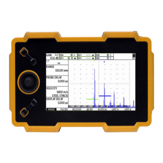
Display screen 4 Principles of operation 4.2 Display screen A-scan display in the zoom mode A-scan representation The USM Go has a high-resolution display screen for the display of the A-scan. A-scan display in the normal mode The gain and the adjusted dB step value are shown in the top left corner of the display screen. -
Page 56: Functions On The Display Screen
4 Principles of operation Display screen Functions on the display screen Functions On the first operating level, the functions of the currently selected function group are shown on the left of the dis- Function groups play screen, next to the A-scan. The names of the seven function groups are shown at the bottom of the display screen. -
Page 57: Gain
Display screen 4 Principles of operation Gain In addition to the measurement reading, the measuring point (peak or flank) is displayed with a symbol in sound The current gain value and the adjusted dB step value path measurements: are always displayed in the top left corner of the screen. ^ = measuring point Peak / = measuring point Flank Examples:... -
Page 58: Status Display Icons
4 Principles of operation Display screen Status display icons To the left of the A-scan, below the measurement line, there is an area for various status displays. The status display icons inform about active functions and certain settings (see Section Status display icons, page 0-7 at the beginning of the present operating manual). -
Page 59: Navigation And Function Keys
Navigation and function keys 4 Principles of operation 4.3 Navigation and function keys Function keys Two key groups consisting of two function keys each are Navigation arranged next to the display screen. The two upper function keys are used for changing the A joystick is used in the USM Go for navigation, for gain and turning the function AUTO 80 on (see Section changing settings, and for selecting adjustment values. -
Page 60: Key Combinations
4 Principles of operation Navigation and function keys Key combinations You can carry out some functions by means of key com- binations. To achieve this, you have to press several keys at the same time (see Section Overview of oper- ator's controls, page 4-2). -
Page 61: Operational Concept
Operational concept 4 Principles of operation 4.4 Operational concept Selecting and setting functions Shown below the A-scan are the seven function groups Operating levels which you can directly select using the navigation. The name of the currently selected function group is high- The USM Go is an easy-to-use instrument. - Page 62 4 Principles of operation Operational concept Coarse and fine adjustment of functions N o t e You can choose between coarse and fine adjustment You can lock the joystick in the USM Go. Any for some functions. changes to the adjustments using the joy- The fine adjustment is made using the navigation.
-
Page 63: Function Home
Operational concept 4 Principles of operation Function HOME This quick adjustment option is available for the follow- ing functions: You can or must select the function HOME in various cases (e.g. to confirm certain settings). To do this, press Function Function group the function keys at the same time (see Section Over- PROBE DELAY... -
Page 64: Activating Functions
4 Principles of operation Operational concept Activating functions Example – Switch over to the second operating level. You have usually two options for choosing functions, for triggering actions, or for changing settings on the sec- – In the function group EVAL, select the function MAG- ond operating level: NIFY GATE. -
Page 65: Important Default Settings
Important default settings 4 Principles of operation 4.5 Important default settings The following languages are available: ● Bulgarian ● Chinese ● German Language setting ● English ● Finnish ● French ● Italian ● Japanese ● Dutch ● Norwegian ● Polish ●... -
Page 66: Units Setting
4 Principles of operation Important default settings Units setting Decimal separator You can use the function UNITS (function group CON- You can choose the decimal separator mark. All data FIG1 on the second operating level) to select the re- are displayed and saved using the selected decimal quired units (mm, in, or µs). -
Page 67: Date Format, Date, And Time
Important default settings 4 Principles of operation Date format, Date, and Time – Switch over to the second operating level. – In the function group CONFIG1, select the function DATE FORMAT. – Press the function keys to change the date format. The time format is changed together with the date for- mat. -
Page 68: Selecting The Instrument Orientation
4 Principles of operation Default settings of the display 4.6 Default settings of the display Selecting the instrument orientation The USM Go is equipped with a high-resolution color display. You can optimize the display according to your own viewing habits and to the operating environment. Selecting the color scheme You can configure the instrument for right-handed or left-handed operation (referred to the probe). -
Page 69: Selecting The A-Scan Color
Default settings of the display 4 Principles of operation Selecting the A-scan color You can choose one of four color schemes using the function COLOR (function group CONFIG1 on the sec- ond operating level). The color scheme determines the color of all displays and of the background. You can set the color of the A-scan separately (please see the sec- tion below). -
Page 70: Selecting The Grid
4 Principles of operation Default settings of the display Selecting the grid Setting the brightness Using the function GRID (function group CONFIG1 on To set the brightness of the display, use the function the second operating level), you can choose a grid for BRIGHTNESS (function group CONFIG1 on the second the A-scan. -
Page 71: Saving The Settings
Saving the settings 4 Principles of operation 4.7 Saving the settings – Switch over to the second operating level. – In the function group CONFIG1, select the function BRIGHTNESS. – Press the function keys to select the required value. N o t e You can extend the operating time by means of the power saver function (see Section Power saving mode, page 5-79). - Page 72 4 Principles of operation Saving the settings – Switch over to the function ACTION and press the A T T E N T I O N function keys to select the function STORE DATA- SET. The filename can be up to 14 characters long for saving data sets.
-
Page 73: Recalling Settings
Saving the settings 4 Principles of operation Recalling settings – Switch over to the function ENTER and briefly press the joystick (USM Go) or the center key of the keypad You can recall and use instrument settings saved to the (USM Go+). -
Page 74: Displaying Dataset Name
4 Principles of operation Saving the settings Displaying dataset name – Switch over to the function ACTION and press the function keys to select the function RECALL DATA- SET. – Switch over to the function FILENAME and briefly press the joystick (USM Go) or the center key of the keypad (USM Go+). - Page 75 Saving the settings 4 Principles of operation – Switch over to the second operating level. A T T E N T I O N – Select the function group EVAL. The filename can be up to 14 characters long – Select the function LARGE. for saving data sets (on the second operating level).
- Page 76 4 Principles of operation Saving the settings 4-24 Rev. 10 (06/2021) USM Go...
- Page 77 Operation USM Go Rev. 10 (06/2021)
-
Page 78: Overview Of The Functions
5 Operation Overview of the functions 5.1 Overview of the functions The first operating level contains seven function groups in the default view. The functions of the USM Go are combined into function N o t e groups on two operating levels. When certain functions are activated, other –... -
Page 79: Function Groups First Operating Level
Overview of the functions 5 Operation Function groups first operating level RANGE This is where you will find functions required for the basic setting of the signal representation on the display screen. PULSER This group is a combination of functions used for setting the pulser. RECEIVER This group is a combination of functions used for setting the receiver. -
Page 80: Function Groups Second Operating Level
5 Operation Overview of the functions Function groups second operating level FILES This is where you will find functions used for the management of files, test reports, and videos. EVAL This group is a combination of functions for evaluation methods. In addition, you can configure the measurement line here (see Section Measurement line, page 4-5). - Page 81 Overview of the functions 5 Operation CONFIG1 This is where you will find various default settings, e.g. language, color, and A-scan display options. CONFIG2 This is where you will find special functions for the instrument setup for test and measurement applications.
-
Page 82: Setting The Gain
5 Operation Setting the gain 5.2 Setting the gain Setting the dB increment of gain To enable you to set the gain quickly and directly, this function is always available to you with the two keys at the top, next to the display screen. You can use the gain to adjust the sensitivity necessary for making echoes from reflectors to be detected visible on the display screen at the required height. - Page 83 Setting the gain 5 Operation The following settings are possible: – Switch to the second operating level. ● LOCK (locked) – In the function group CONFIG2, select the function dB STEP. ● 0.2 dB – Press the function keys to choose the required dB in- ●...
-
Page 84: Assignment Of Function Keys
5 Operation Assignment of function keys 5.3 Assignment of function keys The following settings are possible: ● NONE (no function selected) ● FREEZE (see page 5-68) ● JOYSTICK LOCK (see page 5-76) ● COPY (see page 6-2) ● AUTO80 (see page 5-92) ●... - Page 85 Assignment of function keys 5 Operation – Switch to the second operating level. – In the function group CONFIG2, select the function FUNCTION 1 to assign functions to the upper func- tion key. – Activate the function (see Section Activating func- tions, page 4-12).
-
Page 86: Setting The Display Range (Function Group Range)
5 Operation Setting the display range (function group RANGE) 5.4 Setting the display range N o t e (function group RANGE) For an exact adjustment of the sound veloci- ty and the probe delay, please start by read- ing Chapter 5.8 Calibrating the USM Go, page 5-29. -
Page 87: Range
Setting the display range (function group RANGE) 5 Operation RANGE PROBE DELAY You can use the function RANGE to set the range (the Every probe is equipped with a delay line between the display range) for making measurements. transducer and the coupling face. The sound pulse must first pass through this delay line before it can enter the You can set the display range by coarse adjustment test object. -
Page 88: Velocity
5 Operation Setting the display range (function group RANGE) VELOCITY A T T E N T I O N N o t e Please always make sure that the setting of the function VELOCITY is correct. The USM If µs are selected as units, the function VE- Go calculates all range and distance indica- LOCITY is deactivated for safety reasons tions on the basis of the value adjusted here. -
Page 89: Display Delay
Setting the display range (function group RANGE) 5 Operation DISPLAY DELAY You can use this function to choose whether to display the adjusted display range (for example 250 mm) start- ing from the surface of the test object or in a section of the test object starting at a later point. -
Page 90: Setting The Pulser (Function Group Pulser)
5 Operation Setting the pulser (function group PULSER) 5.5 Setting the pulser (function VOLTAGE (pulser voltage) group PULSER) You can use the function VOLTAGE to set the pulser voltage. The following settings are possible: ● HIGH – high voltage ● LOW – low voltage The setting HIGH is recommended for all tests in which maximum sensitivity is important, e.g. -
Page 91: Energy
Setting the pulser (function group PULSER) 5 Operation ENERGY A T T E N T I O N You can use the function ENERGY to set the penetra- Use the data sheet for your probe to check tion or sound energy. which maximum voltage is allowed to be ap- The following settings are possible: plied. -
Page 92: Width
5 Operation Setting the pulser (function group PULSER) WIDTH N o t e This function is only available if the option square-wave The pulser voltage and the pulse width can pulser is chosen as pulser type (see Section Selecting be automatically limited, depending on the the pulser type, page 5-75). -
Page 93: Damping
Setting the pulser (function group PULSER) 5 Operation DAMPING PRF MODE (pulse repetition frequency) This function is used for matching the probe. By setting The pulse repetition frequency indicates the number of the damping of the probe oscillating circuit you can vary times an initial pulse is triggered per second. - Page 94 5 Operation Setting the pulser (function group PULSER) The following settings are possible: N o t e ● AUTO LOW 400 Hz You can detect and avoid phantom echoes ● AUTO MED 1000 Hz by means of the optional function phantom PRF (see Section Phantom echo detector, ●...
-
Page 95: Setting The Receiver (Function Group Receiver)
Setting the receiver (function group RECEIVER) 5 Operation 5.6 Setting the receiver FREQUENCY (function group RECEIVER) In this function, you can set the frequency of the receiver according to the frequency of your probe. The following settings are possible: ● BROADBAND ●... -
Page 96: Rectify
5 Operation Setting the receiver (function group RECEIVER) RECTIFY DUAL (pulser-receiver separation) You can use the function RECTIFY to select the rectifi- You can use the function DUAL to activate the pulser- cation mode of the echo pulses according to your appli- receiver separation (see Chapter 3.3 Connecting a cation. -
Page 97: Reject
Setting the receiver (function group RECEIVER) 5 Operation REJECT You can use the function REJECT to suppress unwant- ed echo indications, e.g. structural noise from the test object. The height in % indicates the minimum height that the echoes must attain in order for them to be displayed on the screen at all. -
Page 98: Setting The Gates
5 Operation Setting the gates (function groups GATE A and GATE B) 5.7 Setting the gates Tasks of the gates (function groups GATE A ● The gates monitor the area of the test object where and GATE B) you expect to detect a flaw. If an echo exceeds or falls below the gate, an alarm signal is output (see Section Alarms, page 4-6). -
Page 99: A-Start/B-Start (Starting Point Of The Gate)
Setting the gates (function groups GATE A and GATE B) 5 Operation A-START/B-START A-WIDTH/B-WIDTH (starting point of the gate) (width of the gates) You can set the starting point of the gates A or B within You can set the width of the gates A or B within an ad- an adjustment range of 0 …... -
Page 100: A-Threshold/B-Threshold (Response And Measurement Threshold Of The Gate)
5 Operation Setting the gates (function groups GATE A and GATE B) A-THRESHOLD/B-THRESHOLD (response and measurement threshold of the gate) You can define the threshold value of the gates A or B within the range of 5 … 95 % screen height for trigger- ing an alarm if this value is exceeded or not reached. -
Page 101: Tof Mode
Setting the gates (function groups GATE A and GATE B) 5 Operation TOF MODE ● FIRST PEAK The measurement is made as in the case of J- The sound path measurement by means of the echo FLANK, however, with screen resolution. If the eval- evaluation depends on the choice of measuring point. - Page 102 5 Operation Setting the gates (function groups GATE A and GATE B) A T T E N T I O N In any case, the setting of the measuring point in TOF mode for the calibration and for the subsequent test use must always be identical.
-
Page 103: Starting Point Of Gate B
Setting the gates (function groups GATE A and GATE B) 5 Operation Starting point of gate B – Switch to the second operating level. – In the function group CONFIG2, select the function B START MODE. – Press the function keys to choose the required set- ting. -
Page 104: Automatic Gate Height
5 Operation Setting the gates (function groups GATE A and GATE B) Automatic gate height – Switch to the second operating level. – In the function group EVAL, select the function AGT. – Press the function keys to choose the required gate for the automatic adjustment. -
Page 105: Calibrating The Usm Go
Calibrating the USM Go 5 Operation 5.8 Calibrating the USM Go Choice of the measuring point The sound path measurement by means of the echo Calibrating the display range evaluation depends on the choice of measuring point (see Section TOF MODE, page 5-25). Before working with the USM Go, you have to calibrate the instrument: You have to adjust the material velocity A T T E N T I O N... -
Page 106: Calibration With Straight-Beam And Angle-Beam Probes
5 Operation Calibrating the USM Go Calibration with straight-beam and angle- Example beam probes You are carrying out the calibration for the calibration range 100 mm using the calibration standard K1 (thick- ness 25 mm) which is laid down flat. Case A: With known material velocity –... - Page 107 Calibrating the USM Go 5 Operation Case B: With unknown material velocity – Set the required display range using the function RANGE. The two selected calibration echoes must Use the semi-automatic calibration function of the be displayed on the screen. Set the range so that the USM Go with the functions of the function group AUTO- second calibration echo is positioned in the right half CAL for this calibration case.
- Page 108 5 Operation Calibrating the USM Go The correct calibration is confirmed by the message Example AUTOCAL COMPLETE. – Enter the two calibration lines (thicknesses) S-REF 1 The USM Go will then automatically determine the ma- (5.00 mm) and S-REF 2 (20.00 mm). terial velocity and the probe delay, and set the corre- sponding functions accordingly.
- Page 109 Calibrating the USM Go 5 Operation – Record the first calibration echo. – The valid calibration is carried out and confirmed. – Position the gate on the second calibration echo and record the second calibration echo. USM Go Rev. 10 (06/2021) 5-33...
-
Page 110: Calibration Using Dual-Element Probes
5 Operation Calibrating the USM Go Calibration using dual-element probes You can read the material velocity and the probe delay in the function group RANGE. Dual-element probes are especially used for wall thick- ness measurements. The following special features should be taken into account when using these probes: V-path error Dual-element probes produce a v-shaped sound path from the pulser via the reflection from the backwall to the... - Page 111 Calibrating the USM Go 5 Operation With small wall thicknesses, the effect described above – Set the gate threshold to the required height for mea- leads to an echo amplitude drop which has to be espe- suring the sound paths at the echo flanks. cially taken into account with thicknesses <2 mm.
- Page 112 5 Operation Calibrating the USM Go The correct calibration is confirmed by the message AUTOCAL COMPLETE. The material velocity and probe delay are set and displayed. – Check the calibration on one or several known cali- bration lines, e.g. using the stepped calibration block N o t e Always keep in mind that the measurement value is determined at the intersection point...
-
Page 113: Making Measurements
Making measurements 5 Operation 5.9 Making measurements The following example shows the dependency of dis- tance measurement on the echo waveform, i.e. on the height of the gate threshold and thus on the selection of General notes the intersection point at the signal. Please pay attention to the following notes when using the USM Go for measurements: ●... -
Page 114: Db-Difference Measurement (Function Group Db Ref)
5 Operation dB-difference measurement (function group dB REF) 5.10 dB-difference measurement N o t e (function group dB REF) Depending on the evaluation mode selected, one of the function groups DAC/TCG, DGS, AWS D1.1, JISDAC or CNDAC can also be displayed at this point (see Section EVAL MODE, page 5-73). -
Page 115: Recording A Reference Echo
dB-difference measurement (function group dB REF) 5 Operation Recording a reference echo Deleting a reference echo Before using the dB-difference measurement, you have You can delete a stored reference echo at any time. to record a reference echo at first. –... -
Page 116: Echo Height Comparison
5 Operation dB-difference measurement (function group dB REF) Echo height comparison – Switch to the function group EVAL on the second op- erating level. You can compare the echo from any chosen reflector – Use the functions READING to choose one or sever- with the reference echo. -
Page 117: Rating Of Welds (Function Group Aws D1.1)
Rating of welds (function group AWS D1.1) 5 Operation 5.11 Rating of welds – Switch to the second operating level. (function group AWS D1.1) – In the function group EVAL, select the function EVAL MODE and press the function keys to choose the evaluation method AWS D1.1. -
Page 118: Rating Of Welds According To Aws D1.1
5 Operation Rating of welds (function group AWS D1.1) Rating of welds according to AWS D1.1 with: ● A = flaw gain (in dB) The rating of defects in welds according to the specifica- Absolute instrument gain with which the maximum tion AWS D1.1 is based on an evaluation of the signal flaw echo is at 50 % (±5 %) echo height. - Page 119 Rating of welds (function group AWS D1.1) 5 Operation N o t e Make sure that all instrument options for the specific test are calibrated before starting the rating according to AWS D1.1. Remember to peak an echo with an amplitude between 45 % and 55 % screen height.
- Page 120 5 Operation Rating of welds (function group AWS D1.1) The USM Go determines automatically the values of the AWS variables C and D. You can then evaluate the rat- ing D using the corresponding requirements from AWS D1.1. 5-44 Rev. 10 (06/2021) USM Go...
-
Page 121: Flaw Position Calculation With Angle-Beam Probes
Flaw position calculation with angle-beam probes 5 Operation 5.12 Flaw position calculation with – If necessary, switch to the second operating level. angle-beam probes – Select the function group EVAL. In addition to the sound path S, the (reduced) projection distance and the true depth of the flaw are calculated automatically and indicated in the measurement line by means of these functions. -
Page 122: Probe Angle
5 Operation Flaw position calculation with angle-beam probes PROBE ANGLE ● Reduced projection distance rPD Distance from the probe front edge to the position of You can use the function PROBE ANGLE to adjust the the flaw, projected onto the surface. angle of incidence of your probe for the material used. -
Page 123: Thickness
Flaw position calculation with angle-beam probes 5 Operation THICKNESS Example: Object thickness 20 mm ● Angle of incidence 45°, You can use the function THICKNESS to set the wall K = 1, 1. Reflection after 20 mm thickness of the test object. This value is required for the automatic calculation of the true depth. -
Page 124: Value
5 Operation Flaw position calculation with angle-beam probes X VALUE O-DIAMETER You can use the function X VALUE to set the X value You need the function O-DIAMETER when working with (distance of probe front edge from the probe index or circular curved surfaces, e.g. -
Page 125: Color Leg
Flaw position calculation with angle-beam probes 5 Operation COLOR LEG For better orientation, the instrument can mark the legs for the first three reflections with different background colors. – If necessary, switch to the second operating level. – Select the function group EVAL. –... -
Page 126: Defining The Probe Angle
5 Operation Defining the probe angle 5.13 Defining the probe angle – After calibration, switch to the function group AU- TOANG. You can use the function AUTOANG to define the cur- – Select the function BLOCK and press a function key rent index angle of a probe on a reference block. -
Page 127: Block
Defining the probe angle 5 Operation BLOCK The option CUSTOM in the function BLOCK (function group AUTOANG) enables you to design a calibration You can read the preselected test ranges of various cal- standard of your own and to enter its values in the func- ibration standards in the function group BLOCK. -
Page 128: Enabling Options (Upgrade)
5 Operation Enabling options (Upgrade) 5.14 Enabling options (Upgrade) – Switch to the second operating level. – In the function group CONFIG1, select the function CODE and briefly press the joystick (USM Go) or the center key of the keypad (USM Go+). –... -
Page 129: Configuring The Usm Go For
Configuring the USM Go for test tasks 5 Operation 5.15 Configuring the USM Go for test TOF MODE tasks Besides the default settings for the instrument opera- tion, you have to configure the USM Go for calibration and test tasks. You will find functions for this purpose primarily in the function groups EVAL, CONFIG1, and CONFIG2 on the second operating level. - Page 130 5 Operation Configuring the USM Go for test tasks The following settings are possible: A T T E N T I O N ● PEAK (peak measurement) The highest echo in the gate does not have The amplitude and the time-of-flight are measured at to be identical with the echo for which the the absolutely highest amplitude value within the gate sound path is measured.
- Page 131 Configuring the USM Go for test tasks 5 Operation Example: PEAK Example: FLANK With the setting PEAK, the sound path and amplitude measurements are made at the peak of the highest echo in the gate. measured sound path: 12.35 mm amplitude: 86 % measured sound path: 12.74 mm amplitude: 86 %...
- Page 132 5 Operation Configuring the USM Go for test tasks Example: J-FLANK Example: FIRST PEAK With the setting J-FLANK, the sound path measure- Since the gate is not reached yet another time after the ment is made at the intersection point between the gate first PEAK, J-FLANK and FIRST PEAK show the same threshold and the leading edge of the first echo, and the results for A%B: 37 %...
- Page 133 Configuring the USM Go for test tasks 5 Operation A T T E N T I O N In any case, the setting of the measuring point in TOF mode for the calibration and for the subsequent test use must always be identical.
-
Page 134: Phantom Echo Detector
5 Operation Configuring the USM Go for test tasks Phantom echo detector As long as no phantom echoes occur, no distinction can be made in the echo representation between the set- tings ON and OFF. As soon as the phantom echoes appear in the setting ON, they can be recognized at once by a regular move- ment back and forth (approx. -
Page 135: Configuring The Measurement Line
Configuring the USM Go for test tasks 5 Operation Configuring the measurement line N o t e As an alternative to a reading, you can dis- play the virtual alarm LED (see Section LARGE (alarm signal), page 5-64) or the dataset name (see Section Displaying data- set name, page 4-22) in the large box on the far right. - Page 136 5 Operation Configuring the USM Go for test tasks Difference between single measurements Projection distance for gate A of sound path (gate B - gate A) Projection distance for gate B Difference between single measurements of sound path (gate C - gate B) Reduced projection distance for gate A dBrA Echo height in gate A in dB...
- Page 137 Configuring the USM Go for test tasks 5 Operation dBrA Difference of the amplitude of the highest A%rA Amplitude of the highest echo in gate A in echo in gate A below or above the DAC or relation (in %) to the DAC or TCG reference TCG reference curve in dB curve (as 100 %) dBrB...
-
Page 138: Enlarged Display Of Reading
5 Operation Configuring the USM Go for test tasks Enlarged display of reading – Switch to the second operating level. – Select the function group EVAL. – Select the function READING 1 to choose the read- ing for the first position. –... - Page 139 Configuring the USM Go for test tasks 5 Operation Enlarged display of one reading: – Switch to the second operating level. – Select the function group EVAL. – Select the function LARGE to display a single read- ing in enlarged mode. Enlarged display of four readings: –...
-
Page 140: Large (Alarm Signal)
5 Operation Configuring the USM Go for test tasks LARGE (alarm signal) – Switch to the second operating level. – Select the function group EVAL. – Select the function LARGE or READING 4 and press a function key to select the setting VIRTUAL LED. This turns the alarm signal on, and it is displayed next to the readings on top of the A-scan. -
Page 141: Magnify Gate (Spanning The Gate)
Configuring the USM Go for test tasks 5 Operation MAGNIFY GATE (spanning the gate) – Switch to the second operating level. – Select the function group EVAL. – Select the function MAGNIFY GATE to choose the gate for this function. –... -
Page 142: Activating The Magnify Gate Function
5 Operation Configuring the USM Go for test tasks Activating the magnify gate function N o t e In order to use the magnify gate function, a gate must be chosen for it (see Section MAGNIFY GATE (spanning the gate), page 5-65). - Page 143 Configuring the USM Go for test tasks 5 Operation Normal A-scan: A-scan with magnify gate turned on for the gate B: USM Go Rev. 10 (06/2021) 5-67...
-
Page 144: Automatic A-Scan Freeze (Freeze)
5 Operation Configuring the USM Go for test tasks Automatic A-scan freeze (Freeze) ● A-FREEZE The A-scan is frozen automatically when the signal touches the gate A. This setting is suitable e.g. for measurements on hot test objects, for measurements in difficult coupling conditions, or for spot weld test- ing. - Page 145 Configuring the USM Go for test tasks 5 Operation – Switch to the second operating level. – Use the navigation to select the function FREEZE for the brief key press. – Select the function group CONFIG3. – Finally, deactivate the function FUNCTION 1. –...
-
Page 146: Setting The Display
5 Operation Setting the display 5.16 Setting the display The most important default settings of the display screen are described in Chapter 4.6 Default settings of the display: ● Scheme (see page 4-16) ● A-scan color (see page 4-17) ● Grid (see page 4-18) ●... -
Page 147: Ascan Fill
Setting the display 5 Operation ASCAN FILL – Switch to the second operating level. – Select the function group CONFIG2. – Select the function ASCAN FILL and press a function key to choose the filled A-scan display mode. Filled A-scan: You can use the function ASCAN FILL to turn on the filled echo display mode. -
Page 148: Working With Echo Max
5 Operation Setting the display Working with Echo Max – Switch to the second operating level. – Select the function group CONFIG1. – Select the function ECHO MAX and press a function key to turn on the function. Example With a PRF of 1200 Hz and the function ECHO MAX turned on, 1200/60 = 20 A-scans are analyzed as raw data. -
Page 149: General Setup
General setup 5 Operation 5.17 General setup EVAL MODE This is where you can choose a method for evaluating The functions for the basic setup of the instrument are the measured reflector echoes. described in Chapter 4.5 Important default settings: Depending on the options activated, you can choose ●... -
Page 150: Gate Logic
5 Operation General setup Gate logic The following settings are available: ● OFF The gate is turned off, alarms and measurement functions are disabled, and the gate is not visible on the display screen. ● POSITIVE The alarm is triggered if the gate is exceeded. ●... -
Page 151: Selecting The Pulser Type
General setup 5 Operation Selecting the pulser type – Switch to the second operating level. – Select the function group CONFIG2. – Select the function PULSER TYPE and press a func- tion key to choose the pulser type. N o t e If you have chosen the square-wave pulser, the default function ENERGY on the first op- erating level changes into the function... -
Page 152: Locking The Joystick
5 Operation General setup Locking the joystick – Switch to the second operating level. – Select the function group CONFIG1. – Select the function JOY CONTROL and press a func- tion key to lock the joystick by setting the function to OFF. -
Page 153: Configuring The Alarm Output
General setup 5 Operation Configuring the alarm output The settings for VIRTUAL LED and OUTPUT SELECT are logically dependent in the operation of the gates A and B, however, the gate polarity can be set inde- pendently: ● for the VIRTUAL LED by means of GATE A LOGIC and GATE B LOGIC and ●... - Page 154 5 Operation General setup The following settings are available: – Switch to the second operating level. ● A (+) – Select the function group CONFIG2. The alarm is triggered if the gate A is exceeded. – Select the function OUTPUT SELECT. ●...
-
Page 155: Power Saving Mode
General setup 5 Operation Power saving mode You can define the turn-off time within the range of 1 … 30 minutes. – Switch to the second operating level. – Select the function group CONFIG3. – Select the function POWER SAVER and press the function keys to select the required setting. -
Page 156: Tof In Layer
5 Operation General setup TOF in LAYER Defining layers You can define either the thickness of a single layer or the thicknesses of 10 layers within a range of 1.00 … 10.0 mm each. – Switch to the second operating level. –... - Page 157 General setup 5 Operation – Press the joystick (USM Go) or the center key of the keypad (USM Go+) briefly to close the setting. This completes the definition of the layer thicknesses. If the function TOF in LAYER is turned on, only the number of the layer is displayed instead of the numerical reading for SA, SB, and SC in the measurement line on top of the A-scan, e.g.
-
Page 158: Backwall Echo Attenuation (Bea)
5 Operation General setup Backwall echo attenuation (BEA) the A-scan. The backwall echo can then be selectively integrated into the flaw evaluation. However, the backwall echo attenuation also allows to systematically increase the gain. In this way, you can, for example, only increase the gain within the flaw ex- pectancy range in order to peak the echo in this range. -
Page 159: Displaying The Envelope Curve (Envelope)
General setup 5 Operation Displaying the envelope curve – Switch to the second operating level. (ENVELOPE) – Select the function group CONFIG3. – Select the function ENVELOPE and press a function key to turn on the envelope curve. – Switch to the function ENVELOPE COLOR. –... -
Page 160: Automatic Gain Control (Auto Gain Control)
5 Operation General setup Automatic gain control (Auto Gain Control) The automatic gain control of the USM Go keeps the echo amplitude fully automatically at a specified screen height and, in this way, compensates for the amplitude variations of the signal received. This enables to clearly improve especially the wall thickness measurement and to make it easier. - Page 161 General setup 5 Operation – Switch to the second operating level. N o t e – Select the function group CONFIG4. The automatic gain control is helpful, e.g. in – Select the function CTRL MODE and press a function the calibration using AUTOCAL (setting key to turn on the automatic gain control.
-
Page 162: Calibration Reminder
5 Operation General setup Calibration reminder You can turn on a short-term calibration reminder for a time period within the range of 0.5 … 4 hours and a re- minder for the yearly calibration. In the case of the yearly reminder, define the date at which the calibration should be carried out. -
Page 163: Password Protection
General setup 5 Operation Password protection Yearly calibration reminder – Switch to the second operating level. – Select the function group CONFIG3. – Switch to the function DATE and briefly press the joy- stick (USM Go) or the center key of the keypad (USM Go+). - Page 164 5 Operation General setup To activate this function, you have to set a password. Af- – Use the navigation to enter the first character of the ter saving the password, it is only possible to switch to password. the mode Expert after entering the password. –...
- Page 165 General setup 5 Operation – Use the navigation to enter the current password. Protecting settings – Press the joystick (USM Go) or the center key of the After saving a password, you can protect the individual keypad (USM Go+) briefly to close the entry of the functions of the USM Go.
- Page 166 5 Operation General setup – Switch to the function PARAM MODE and briefly Login as Expert press the joystick (USM Go) or the center key of the – Switch to the second operating level. keypad (USM Go+). – Select the function group CONFIG4. –...
-
Page 167: Distance-Amplitude Correction (Dac)
Distance-amplitude correction (DAC) 5 Operation 5.18 Distance-amplitude correction (DAC) The USM Go has an optional DAC function for the echo evaluation by means of the distance-amplitude correc- tion (DAC). Due to the angle of beam spread and the sound attenu- ation in the material, the echo height of equally sized re- flectors depends on the distance to the probe. -
Page 168: Recording A Dac Curve
5 Operation Distance-amplitude correction (DAC) Recording a DAC curve – Select the function group DAC/TCG. – Use the navigation to move upwards in order to dis- A T T E N T I O N play the specific function groups and functions for the DAC/TCG. - Page 169 Distance-amplitude correction (DAC) 5 Operation – Select the function gate a start and position the gate – Position the gate A on the second DAC echo. A on the first DAC echo. – Select the function AUTO80 and press a function key to automatically set the echo to 80 % screen height.
-
Page 170: Setting Up The Dac
5 Operation Distance-amplitude correction (DAC) Setting up the DAC – Finally, select the function FINISH and press a function key to finish the recording of the DAC echoes. The fin- – Select the function group SETUP. The function TCG/ ishing is confirmed by the indication (STORED). DAC MODE is automatically set to DAC. -
Page 171: Turning The Dac Evaluation Off
Distance-amplitude correction (DAC) 5 Operation Turning the DAC evaluation off – Select the function TCG/DAC MODE and press a function key to switch to TCG (time-corrected gain) You can turn the DAC evaluation off any time. mode. The horizontal line of the time-corrected gain is displayed in the A-scan and all echoes are dis- –... -
Page 172: Deleting The Dac Curve
5 Operation Distance-amplitude correction (DAC) Deleting the DAC curve Editing DAC points You can delete the DAC curve at any time. After this, the You can edit individual DAC points at any time. DAC evaluation is not possible until you have recorded –... -
Page 173: Adding Dac Points
Distance-amplitude correction (DAC) 5 Operation Multiple DAC curves – Select the function POINT POS. and press the func- tion keys to change the distance of the point. Adding DAC points You can add individual DAC points at any time. – Select the function group EDIT. The function POINT is automatically set to NEW in order to define a new DAC point. - Page 174 5 Operation Distance-amplitude correction (DAC) As an alternative you can set the offset for each curve in- – Select the function MODE and press a function key to dividually and turn off single curves of the multiple curves. turn on the individual curve definition by means of In this case, the adjustment range is -24 …...
-
Page 175: Aws D1.1 In Dac/Tcg
Distance-amplitude correction (DAC) 5 Operation AWS D1.1 in DAC/TCG Sensitivity correction You can use the function TRANSFER CORR. to com- pensate for transfer losses in the material to be tested. A correction is necessary if the test object and the refer- ence standard have different surface qualities. -
Page 176: Echo Evaluation Using Dac/Tcg
5 Operation Distance-amplitude correction (DAC) Echo evaluation using DAC/TCG Change in the probe delay with DAC/TCG Generally, a change in the probe delay automatically To be able to evaluate a flaw echo by means of the also affects the shape of the sound field. This means DAC/TCG, certain conditions must be met: that a new recording of the reference echo would be the- ●... - Page 177 Distance-amplitude correction (DAC) 5 Operation Automatic variation of the measuring point in TOF mode An echo amplitude evaluation is normally carried out at the echo peak of the signal under examination because this is the only way of ensuring that the displayed echo amplitude and the sound path (projection distance, depth position) always belong to the highest echo in the gate.
-
Page 178: Distance-Amplitude Curve According To Jis Z3060-2002 (Jisdac)
5 Operation Distance-amplitude curve according to JIS Z3060-2002 (JISDAC) 5.19 Distance-amplitude curve Activating JISDAC (DAC according to JIS) according to JIS Z3060-2002 (JISDAC) The USM Go has an optional DAC function for the echo evaluation by means of the distance-amplitude correc- tion (DAC) and an additional class rating according to JIS Z3060-2002. -
Page 179: Recording A Dac Curve
Distance-amplitude curve according to JIS Z3060-2002 (JISDAC) 5 Operation Recording a DAC curve – Select the function group JISDAC. – Use the navigation to move upwards in order to dis- A T T E N T I O N play the specific function groups and functions for the JISDAC. - Page 180 5 Operation Distance-amplitude curve according to JIS Z3060-2002 (JISDAC) – Select the function gate a start and position the gate – Position the gate A on the second DAC echo. A on the first DAC echo. – Select the function AUTO80 and press a function key to automatically set the echo to 80 % screen height.
-
Page 181: Setting Up Jisdac
Distance-amplitude curve according to JIS Z3060-2002 (JISDAC) 5 Operation Setting up JISDAC – Finally, select the function FINISH and press a function key to finish the recording of the DAC echoes. The fin- – Select the function group SETUP. The function JIS- ishing is confirmed by the indication (STORED). -
Page 182: Sensitivity Correction
5 Operation Distance-amplitude curve according to JIS Z3060-2002 (JISDAC) Sensitivity correction Turning the JISDAC evaluation off You can use the function TRANSFER CORR. to com- You can turn the JISDAC evaluation off at any time. pensate for transfer losses in the material to be tested. –... -
Page 183: Deleting The Dac Curve
Distance-amplitude curve according to JIS Z3060-2002 (JISDAC) 5 Operation Deleting the DAC curve Echo evaluation using DAC You can delete the DAC curve at any time. After this, the To be able to evaluate a flaw echo by means of the JISDAC evaluation is not possible until you have record- DAC, certain conditions must be met: ed a new DAC curve. - Page 184 5 Operation Distance-amplitude curve according to JIS Z3060-2002 (JISDAC) Change in the probe delay Automatic variation of the measuring point in TOF mode Generally, a change in the probe delay automatically also affects the shape of the sound field. This means An echo amplitude evaluation is normally carried out at that a new recording of the reference echo would be the- the echo peak of the signal under examination because...
-
Page 185: Distance-Amplitude Curve According To Jb/T4730 And Gb 11345 (Cndac)
Distance-amplitude curve according to JB/T4730 and GB 11345 (CNDAC) 5 Operation 5.20 Distance-amplitude curve Evaluations according to CNDAC according to JB/T4730 and After recording the reference echo, the CNDAC shows GB 11345 (CNDAC) the reference lines RL, SL, and EL depending on the corresponding choice in the functions CODE NAME (standard) and BLOCK (reference block). -
Page 186: Standards And Reference Blocks
5 Operation Distance-amplitude curve according to JB/T4730 and GB 11345 (CNDAC) Standards and reference blocks CODE NAME BLOCK Ø side-drilled hole (mm) Wall thickness test object (mm)RL (dB) SL (dB) EL (dB) 11345A – DAC – 10 DAC – 16 11345B –... -
Page 187: Activating The Cndac
Distance-amplitude curve according to JB/T4730 and GB 11345 (CNDAC) 5 Operation Activating the CNDAC Recording a DAC curve A T T E N T I O N Before starting to record a reference curve, the instrument has to be correctly calibrated (see Chapter 5.8 Calibrating the USM Go, page 5-29). - Page 188 5 Operation Distance-amplitude curve according to JB/T4730 and GB 11345 (CNDAC) – Select the function group CNDAC. – Select the function gate a start and position the gate A on the first DAC echo. – Use the navigation to move upwards in order to dis- play the specific function groups and functions for the CNDAC.
- Page 189 Distance-amplitude curve according to JB/T4730 and GB 11345 (CNDAC) 5 Operation – Position the gate A on the second DAC echo. – Finally, select the function FINISH and press a func- tion key to finish the recording of the DAC echoes. –...
-
Page 190: Setting Up Cndac
5 Operation Distance-amplitude curve according to JB/T4730 and GB 11345 (CNDAC) Setting up CNDAC – Select the function CNDAC TYPE and press the function keys to choose the required line display type – Select the function group SETUP. The function CN- (STRAIGHT, CURVED, or POLYNOMIAL). -
Page 191: Sensitivity Correction
Distance-amplitude curve according to JB/T4730 and GB 11345 (CNDAC) 5 Operation Sensitivity correction You can use the function TRANSFER CORR. to com- pensate for transfer losses in the material to be tested. A correction is necessary if the test object and the refer- ence standard have different surface qualities. -
Page 192: Adjusting Reference Lines
5 Operation Distance-amplitude curve according to JB/T4730 and GB 11345 (CNDAC) Adjusting reference lines Turning the CNDAC evaluation off You can change the reference lines for RL and EL at You can turn the CNDAC evaluation off at any time. any time. -
Page 193: Deleting The Dac Curve
Distance-amplitude curve according to JB/T4730 and GB 11345 (CNDAC) 5 Operation Deleting the DAC curve Echo evaluation using DAC You can delete the DAC curve at any time. After this, the To be able to evaluate a flaw echo by means of the CNDAC evaluation is not possible until you have record- DAC, certain conditions must be met: ed a new DAC curve. - Page 194 5 Operation Distance-amplitude curve according to JB/T4730 and GB 11345 (CNDAC) Change in the probe delay Automatic variation of the measuring point in TOF mode Generally, a change in the probe delay automatically also affects the shape of the sound field. This means An echo amplitude evaluation is normally carried out at that a new recording of the reference echo would be the- the echo peak of the signal under examination because...
-
Page 195: Evaluation According To The Dgs Method
Evaluation according to the DGS method 5 Operation 5.21 Evaluation according to the ● Distance D between the probe coupling face and the circular disk-shaped equivalent reflector DGS method ● Difference in gain G between a circular disk-shaped equivalent reflector and a reference reflector, e.g. an The USM Go offers the optional evaluation method infinitely large backwall DGS (distance - gain - size). - Page 196 5 Operation Evaluation according to the DGS method The following parameters of the probe affect the curve You can adjust these parameters in the USM Go in such shape: a way that you can use the DGS method with many dif- ferent probes and on various materials.
-
Page 197: Validity Of The Dgs Method
Evaluation according to the DGS method 5 Operation Validity of the DGS method ● The evaluation must be carried out using the same probe that was used for recording the reference echo. Echo amplitude evaluations using the DGS method are Another probe of the same type can be used after re- only reliable and reproducible under the following condi- cording a new reference echo. - Page 198 5 Operation Evaluation according to the DGS method Change in the probe delay with DGS Automatic variation of the measuring point in TOF mode Generally, a change in the probe delay automatically also affects the shape of the sound field. This means An echo amplitude evaluation is normally carried out at that a new recording of the reference echo for the DGS the echo peak of the signal under examination because...
-
Page 199: Starting The Echo Height Evaluation According To Dgs
Evaluation according to the DGS method 5 Operation Starting the echo height evaluation Basic settings for the DGS measurement according to DGS You can choose the probe and set other DGS parame- ters in this step. – Select the function group DGS. –... - Page 200 5 Operation Evaluation according to the DGS method ● DGS CURVE (recording curve for DGS evaluation) ● DELAY VELOCITY You can use this to select the circular disk-shaped re- Sound velocity in the probe delay line; preset for pro- flector diameter to be used for displaying the DGS grammed probes.
-
Page 201: Recording A Reference Echo And Turning The Dgs Curve On
Evaluation according to the DGS method 5 Operation Recording a reference echo and turning the – Select the function group GATE A. DGS curve on – Select the function TOF MODE and press a function key to set the measuring point in TOF mode to PEAK. To be able to display the required DGS curve, you have –... - Page 202 5 Operation Evaluation according to the DGS method – Select the function group SETUP. – Select the function DGS MODE and press a function Taking the general DGS diagram as a basis, the USM key to turn on the DGS evaluation. The DGS curve is Go calculates the required test sensitivity for displaying calculated and displayed in the A-scan.
-
Page 203: Locks, Error Messages
Evaluation according to the DGS method 5 Operation Locks, error messages The gain can be varied at any time. The difference in re- lation to the calibration value during the DGS calibration As long as a valid reference echo is stored, no functions is directly displayed in the top left corner on top of the can be changed which could cause an incorrect DGS gain value (without designation). -
Page 204: Sound Attenuation And Transfer Correction
5 Operation Evaluation according to the DGS method Sound attenuation and transfer correction Using multiple DGS curves There are two possibilities for setting the sound attenu- After turning the DGS evaluation on, at least one curve ation in the test object: is displayed for a certain ERS (equivalent reflector size). -
Page 205: Turning The Dgs Evaluation Off
Evaluation according to the DGS method 5 Operation Turning the DGS evaluation off Deleting a DGS reference echo You can turn the DGS evaluation off at any time. You can delete the echo of the reference reflector. After this, the DGS evaluation is not possible until you have –... -
Page 206: Probe Data
5 Operation Evaluation according to the DGS method Probe data Probe name Wavelength Minimum diameter Near-field Minimum in steel of side-drilled hole length in steel distance in steel [mm] [mm] [mm] [mm] B1-S B2-S B4-S MB2-S MB4-S MB5-S 7 … 9 MWB …-2 10 …... - Page 207 Evaluation according to the DGS method 5 Operation Probe Wavelength in steel Focus depth in steel [mm] [mm] MSEB-2 8 ±2 MSEB-4 10 ±2 MSEB-4 0° 18 ±4 MSEB-5 10 ±2 SEB-1 20 ±4 SEB-2 KF5 6 ±2 SEB-4 KF8 6 ±2 SEB-2 15 ±3...
- Page 208 5 Operation Evaluation according to the DGS method N o t e The DGS curves for the dual-element probes are not derived from the general DGS diagram but have been individually mea- sured for steel (5920 m/s) and stored in the instrument.
-
Page 209: Truedgs Angle-Beam Probes
Evaluation according to the DGS method 5 Operation ® trueDGS angle-beam probes The following probes using the trueDGS technology are currently available: ® trueDGS angle-beam probes generate a rotationally ● MWB45-2 tD (probe # 35) symmetric sound field in the material to be tested like vertically beaming circular elements. - Page 210 5 Operation Evaluation according to the DGS method 5-134 Rev. 10 (06/2021) USM Go...
-
Page 211: Documentation
Documentation USM Go Rev. 10 (06/2021) -
Page 212: Test Reports
6 Documentation Test reports 6.1 Test reports Storing using COPY N o t e Storing test reports If you repeatedly select the same filename for storing, a consecutive numbering is auto- You can use the USM Go to store test reports and A- matically attached to the filename, for exam- scans. - Page 213 Test reports 6 Documentation Storing on the second operating level – Press the joystick (USM Go) or the center key of the keypad (USM Go+) briefly to choose the selected di- rectory. – Switch to the function ACTION and press the function keys to select one of the functions STORE REPORT (test report) or FAST REPORT (fast report).
-
Page 214: Displaying Test Reports
6 Documentation Test reports Displaying test reports – Switch to the function ENTER and briefly press the joystick (USM Go) or the center key of the keypad You can display test reports saved to the SD card on the (USM Go+). display screen of your instrument. - Page 215 Test reports 6 Documentation – Switch to the function ACTION and press the function keys to select the function SHOW REPORT. – Switch to the function FILENAME and briefly press the joystick (USM Go) or the center key of the keypad (USM Go+).
-
Page 216: Printing Test Reports
6 Documentation Test reports Printing test reports – Use the navigation to shift the view in order to display other data of the test report, provided they were also The USM Go is not meant to be directly connected to a selected during storing. -
Page 217: Deleting Test Reports
Test reports 6 Documentation Deleting test reports N o t e You can delete files and directories easily by inserting Only files of the type UGO are deleted. Files the SD memory card into the SD card reader of your PC of the types BMP and JPG are retained. - Page 218 6 Documentation Test reports – Switch to the function FILENAME and briefly press the joystick (USM Go) or the center key of the keypad (USM Go+). – Use the navigation to select the name of the required dataset file. – Press the joystick (USM Go) or the center key of the keypad (USM Go+) briefly.
-
Page 219: Storing The A-Scan And Parameters In The Test Report
Test reports 6 Documentation Storing the A-scan and parameters in the – Switch to the second operating level. test report – In the function group FILES, select the function IMAGE IN REPOR and press a function key to turn on the function by choosing YES. –... -
Page 220: Storing Memos
6 Documentation Storing memos 6.2 Storing memos Creating a new memo file – Switch to the second operating level. – In the function group FILES, select the function MEMO EDIT and briefly press the joystick (USM Go) or the center key of the keypad (USM Go+). –... -
Page 221: Editing A Memo File
Storing memos 6 Documentation Editing a memo file N o t e You can edit a memo file saved to the SD memory card You can use any text editor to edit memo at any time. files by inserting the SD memory card into –... -
Page 222: Attaching A Memo File To Test Report
6 Documentation Storing memos Attaching a memo file to test report Next time a test report is stored, the contents of the se- lected memo file are attached to the end of the test re- You can attach the text of a memo file to one or several port. -
Page 223: Storing A Report Header
Storing a report header 6 Documentation 6.3 Storing a report header Creating a new header file – Switch to the second operating level. – In the function group FILES, select the function HEADER EDIT and briefly press the joystick (USM Go) or the center key of the keypad (USM Go+). -
Page 224: Editing A Header File
6 Documentation Storing a report header Editing a header file N o t e You can edit a header file saved to the SD memory card You can use any text editor to edit header at any time. files by inserting the SD memory card into –... -
Page 225: Including A Header File In The Test Report
Storing a report header 6 Documentation Including a header file in the test report Next time a test report is stored, the contents of the se- lected header file are inserted into the head of the test You can insert the text of a header file into one or sev- report. -
Page 226: Viewing And Storing Parameters
6 Documentation Viewing and storing parameters 6.4 Viewing and storing parameters – In the function group FILES, select the function PA- RAMETERS and briefly press the joystick (USM Go) or the center key of the keypad (USM Go+). The first page of the list of all parameters and settings is dis- played on the screen. -
Page 227: Videos
Videos 6 Documentation 6.5 Videos During recording, various control functions and the op- eration of the gates are available to you. In addition, you can set several flags in order to find single sequences You can record and replay videos. During recording, all faster later on. - Page 228 6 Documentation Videos – Use the navigation to choose the first character of the You will then automatically switch to the first operating filename. level with the A-scan. – Use the navigation to switch to the next position, and choose the next character. –...
-
Page 229: Viewing A Video
Videos 6 Documentation Viewing a video – In the function group RECORD, select the function RECORD and press a function key. The video re- cording starts. – Switch to the function FLAG and press a function key to set a flag. The name of the flag corresponds to the number of the single frame when the function key is pressed. - Page 230 6 Documentation Videos – Switch to the second operating level. You will then automatically switch to the first operating level with the A-scan. The replay starts automatically. – In the function group FILES, select the function SOURCE/DEST. – Press the function keys to select the memory loca- tion.
-
Page 231: Documentation Using Ultramate
– Switch to the function SPEED and press the function keys to change the replay speed. The special application program UltraMATE provided by Waygate Technologies enables you to remotely control – In the function REPLAY, select the function PLAY the USM Go and to include instrument settings in ASCII and press a function key to interrupt the recording. -
Page 232: Data Recorder (Option)
6 Documentation Data Recorder (option) 6.7 Data Recorder (option) You can store readings in a grid matrix and, in this way, structure them according to the test tasks. The grid ma- trix consists of rows and columns. The functions of the option Data Recorder are available to you in the function group DR on the second operating In this way, you can e.g. -
Page 233: Creating A Data Recorder File
Data Recorder (option) 6 Documentation Creating a Data Recorder file A T T E N T I O N After generating the file, you can no longer change the number of rows and columns that you have defined using the function BOT- TOM. - Page 234 6 Documentation Data Recorder (option) – Press the joystick (USM Go) or the center key of the – Press the joystick (USM Go) or the center key of the keypad (USM Go+) briefly to close the filename en- keypad (USM Go+) briefly to close the selection. try.
-
Page 235: Activating A Data Recorder File
Data Recorder (option) 6 Documentation Activating a Data Recorder file After creating the Data Recorder file, the number of rows and columns is indicated. You can activate every one of the Data Recorder files created and use them for storing readings. –... -
Page 236: Storing Readings In The Grid Matrix
6 Documentation Data Recorder (option) Storing readings in the grid matrix – Press the joystick (USM Go) or the center key of the keypad (USM Go+) briefly to close the selection of When you see the grid matrix on the display screen, you the filename. -
Page 237: Deleting Readings
Data Recorder (option) 6 Documentation Deleting readings If an A-scan has been stored together with the reading, you will see a mark in the top left corner of the cell. You cannot overwrite any readings. If you want to change a reading, you have to delete the stored read- ing, after which you will be able to store a new reading in the empty cell. -
Page 238: A-Scan Preview
6 Documentation Data Recorder (option) A-scan preview – Switch to the first operating level. You will see the A- scan. If you select a cell containing a stored reading with an A- – Press the joystick (USM Go) or the center key of the scan attached to it, the A-scan is displayed next to the keypad (USM Go+) briefly. -
Page 239: Turning The Grid Matrix On/Off
Data Recorder (option) 6 Documentation Turning the grid matrix on/off Turning the grid matrix off – Switch to the second operating level. – In the function group DR, select the function DR VIEW. – Press a function key to set the function to OFF. This turns off the functions of the grid matrix. - Page 240 6-30 Rev. 10 (06/2021) USM Go...
-
Page 241: Maintenance And Care
Maintenance and care USM Go Rev. 10 (06/2021) -
Page 242: Instrument Care
7 Maintenance and care Instrument care 7.1 Instrument care 7.2 Battery care Clean the instrument and its accessories using a moist Battery care cloth. The following are exclusively recommended for cleaning: The capacity and life of batteries mainly depend on the correct handling. -
Page 243: Charging The Batteries
Maintenance 7 Maintenance and care 7.3 Maintenance Charging the batteries You can charge the lithium-ion battery either within the The USM Go requires basically no maintenance. instrument itself or by means of the external charger recommended by us. Please observe the operating in- A T T E N T I O N structions for the charger in this regard. -
Page 244: Software Updates
7 Maintenance and care Software updates 7.4 Software updates You can install the latest software updates for the USM Go yourself. Look up the version installed in your instru- ment on the second operating level. – Switch to the function group CONFIG2 and further to the function ABOUT. -
Page 245: Download Of Update Files
Installing an update You can download the latest software version for your N o t e instrument from the Waygate Technologies website by Only one file with the extension .sdu may be means of any customary web browser. located in the main directory of the SD card After downloading, you have to copy the update file to for the installation. - Page 246 7 Maintenance and care Software updates – Press the inner end of the Gain key (1), the further end of the Function key (2), and the Power key (3), and hold all three keys pressed until the display screen is turned on and the message FLASH UP- GRADE MODE appears.
-
Page 247: Interfaces And Peripherals
Interfaces and Peripherals USM Go Rev. 10 (06/2021) -
Page 248: Interfaces
8 Interfaces and Peripherals Interfaces 8.1 Interfaces Overview The interfaces are located under the watertight cover on the top of the instrument. – Push the lock of the hinged cover (1) in the direction of the arrow in order to open the cover. –... -
Page 249: Usb Interface
PC. and for service purposes for the Customer Support of Waygate Technologies. When you connect the instrument to a PC via a standard USB cable, the SD memory card inserted into the instru- Pin assignment of the connecting cable ment is added to the list of active drives on the PC. -
Page 250: Peripherals
8 Interfaces and Peripherals Peripherals 8.2 Peripherals The USM Go is not provided for the direct connection of peripherals, e.g. printers or monitors. For more details on printing, see Section Printing test reports, page 6-6. Rev. 10 (06/2021) USM Go... -
Page 251: Appendix
Appendix USM Go Rev. 10 (06/2021) -
Page 252: Function Directory
9 Appendix Function directory 9.1 Function directory N o t e Some functions are only available if the cor- responding options are enabled by entering the license code. Function Function group Operating level Description see page A INDICATION AWS D1.1 first 5-41 ASCAN FILL... - Page 253 Function directory 9 Appendix Function Function group Operating level Description see page OUTPUT SELECT CONFIG2 second 5-77 RECORD dB REF second Recording of a reference echo for the 5-38 dB difference measurement FINISH CNDAC first Finishing of the recording of points (curve points) 5-109 for the DAC FINISH...
- Page 254 9 Appendix Function directory Function Function group Operating level Description see page B START MODE. CONFIG2 second Basis for the starting point of the gate B 5-27 B-START GATE B first Starting point of the gate B 5-22 B-WIDTH GATE B first Starting point of the gate B 5-22...
- Page 255 Function directory 9 Appendix Function Function group Operating level Description see page GATE A LOGIC CONFIG2 second Evaluation logic of the gate A 5-74 GATE B LOGIC CONFIG2 second Evaluation logic of the gate B 5-74 BLOCK AUTOANG first C ATTENUATION AWS D1.1 first 5-41...
- Page 256 9 Appendix Function directory Function Function group Operating level Description see page DIRECTORY FILES second Choice of the directory for file actions DR VIEW second Display of grid matrix (Data Recorder) 6-22 DR THICKNESS second Choice of the measuring method for storing readings in the 6-22 grid matrix (Data Recorder) DIAMETER...
- Page 257 Function directory 9 Appendix Function Function group Operating level Description see page FUNCTION 1 CONFIG2 second Assignment of the function key 1 (upper end of key) FUNCTION 2 CONFIG2 second Assignment of the function key 2 (lower end of key) ABOUT CONFIG2 second...
- Page 258 9 Appendix Function directory Function Function group Operating level Description see page HEADER EDIT FILES second Editing of data for the header of the test report 6-14 BOTTOM second Setting of coordinates of the last cell in the grid matrix (Data 6-22 Recorder) DELETE REF...
- Page 259 Function directory 9 Appendix Function Function group Operating level Description see page O-DIAMETER TRIG second Toggling between plane-parallel and curved test objects 5-48 O-DIAMETER EVAL second 5-48 THICKNESS TRIG first Entry of test object thickness for calculating the true flaw 5-47 depth THICKNESS...
- Page 260 9 Appendix Function directory Function Function group Operating level Description see page VELOCITY RANGE first Velocity 5-10 LAYER EDIT CONFIG3 second Adjustment of layer thicknesses for the function TOF in 5-80 LAYER LAYER TYPE CONFIG3 second Toggling between a single layer and 10 layers 5-80 PULSER TYPE CONFIG2...
-
Page 261: Eu Declaration Of Conformity
Should you nevertheless detect an error on your instru- ment, power the instrument off and remove the batter- ies. Inform your local Waygate Technologies customer service and support, indicating the error and describing Keep the shipping container for any repairs possibly re- quired which cannot be made on the spot. - Page 262 Manufacturer/Service addresses If there is anything special that you would like to know about the use, handling, operation, and specifications of Waygate Technologies the instruments, please contact your nearest Waygate Baker Hughes Digital Solutions Technologies representative or turn directly to:...
-
Page 263: Environmental Protection Regulations
WEEE directive (Waste Electrical and Electronic Equipment) If you need more information on the collection, reuse, and recycling of recyclable material, please contact your Waygate Technologies is an active participant in Eu- local waste management company. rope's Waste Electrical and Electronic Equipment Visit ec.europa.eu/environment/waste/weee/index- (WEEE) take-back initiative, directive 2012/19/EU. -
Page 264: Disposal Of Batteries
9 Appendix Environmental protection regulations Disposal of batteries What do the markings mean? Batteries and accumulators must be marked (either on This product contains batteries that cannot be disposed the battery, on the accumulator, or on their packaging, of as unsorted municipal waste in the European Union. depending on the size) with the separate collection sym- Please read carefully the data sheets for the battery bol. - Page 265 Environmental protection regulations 9 Appendix The risks and your role in minimizing them ● Lead is poisonous in all compounds. It accumulates in the body so that any form of exposure is critical. In- By participating in the proper waste disposal, you would gestion and inhalation of lead can cause severe inter- make a valuable contribution towards reducing the dam- nal injuries.
- Page 266 9-16 Rev. 10 (06/2021) USM Go...
-
Page 267: Specifications
Specifications USM Go Rev. 10 (06/2021) 10-1... -
Page 268: Specifications Of Usm Go And Usm Go
10 Specifications Specifications of USM Go and USM Go+ 10.1 Specifications of USM Go and USM Go+ Display screen Active range (W × H) 108.0 × 64.8 mm, diagonal 5 inches Size 5 inches Resolution (W × H) 800 × 480 pixels Contrast ratio ≥300 Brightness... -
Page 269: Display
Specifications of USM Go and USM Go+ 10 Specifications Display Display shift –15 … 3,500 µs (DISPLAY DELAY) Probe delay 0 … 1,000 µs Velocity 250 … 16,000 m/s Automatically optimized 15 … 2,000 Hz, 3 automatic setting modes: Auto Low, Auto Med, Auto High, Manual Connectors Probe connectors 2 ×... -
Page 270: Memory
10 Specifications Specifications of USM Go and USM Go+ Memory Card slot SD card slot for all standard SD cards Pulser Pulser mode Spike pulser, optionally: Square-wave pulser Pulser voltage (SQ mode) 120 … 300 V, in steps of 10 V with a tolerance of 10 % Pulser falling/rising time max. -
Page 271: Receiver
Specifications of USM Go and USM Go+ 10 Specifications Receiver Digital gain Dynamic range 110 dB, adjustable in steps of 0.2 dB Analog bandwidth 0.9 … 20 MHz Equivalent input noise <80 µV, across the full bandwidth Recovery time Target of <10 µs Input linearity 5 % for method E317, for output data on all 4 ADC's Filters... -
Page 272: Gates
10 Specifications Specifications of USM Go and USM Go+ Gates Independent gates 2 gates A and B (triggering by gate A), gate C (option) Rectification positive half-wave, negative half-wave, full wave, RF signal Measuring position Peak, Flank, J-FLANK, FIRST PEAK Memory Capacity 2 GB, SD card... -
Page 273: Environment
Specifications of USM Go and USM Go+ 10 Specifications Environment Battery Operating time: 6 hours with full charge Charging method (standard): internal with charger/power adapter Charging method (optional): external charger Charge level: proportional charge level indicator Charger/power adapter Universal power supply unit 100 … 240 VAC, 50/60 Hz, meets the requirements of CCC, CE, UL, CSA, and PSE Size (W ×... -
Page 274: Protection
10 Specifications Specifications of USM Go and USM Go+ Protection Damp heat and humidity (storage) 10 cycles: 10 hrs at +60 … +30 °C, 10 hrs at +30 … +60 °C, transition within 2 hrs (507.4) Temperature shock (storage) 3 cycles: 4 hrs at -20 … +60 °C, 4 hrs at +60 °C transition within 5 minutes (503.4, Procedure II) Vibration: General exposure: 1 hr per axis,... -
Page 275: Options
Specifications of USM Go and USM Go+ 10 Specifications Storage temperature range –20 … +60 °C, 24 hrs including battery Compliance EMC/EMI: EN 55011, EN 61000-6-2:2001 Ultrasound: EN 12668, ASTM E1324, E317, ANSI/NCSL Z 540-1-1994, MIL STD 45662A, MIL STD 2154 Options AWS calibration tool, according to AWS D1.1 Structural Welding Code DAC calibration tool, 16 points, according to EN ISO 11666, EN ISO... - Page 276 10 Specifications Specifications of USM Go and USM Go+ for pulser parameter optimization, voltage setting 120 … 300 V in steps of 10 V, pulse width setting 30 … 500 ns in steps of 10 ns JIS, CN, DGS, BEA, Phantom-PRF Phantom-PRF for the identification of erroneous echoes caused by multi- ple reflections in low-attenuation materials JIS, CN, DGS, BEA...
-
Page 277: Specifications According To
Specifications according to EN 12668 10 Specifications 10.2 Specifications according to EN 12668 You will find the specifications according to EN 12668 for your instrument on the USB stick included in the standard package. USM Go Rev. 10 (06/2021) 10-11... - Page 278 10-12 Rev. 10 (06/2021) USM Go...
- Page 279 Index USM Go Rev. 10 (06/2021) 11-1...
- Page 280 11 Index Storing 6-9 Zoom 4-3 ABOUT 5-52, 7-4 Zoomed 6-29 AC power adapter 3-2 A-SCAN COLOR 4-17 ACTION 4-20, 4-22, 6-3, 6-5, 6-7 A-scan color 4-17 Addresses 9-11 A-scan freeze 5-68 Adjustment range 4-11 ASCANFILL 5-71 ADV DIRECTION 6-24 A-START 5-23 A-FREEZE 5-68 A-THRESHOLD 5-24...
- Page 281 11 Index B-FREEZE 5-68 BLOCK 5-51 B REFERENCE 5-99 BOTTOM 6-24 Backwall Echo Attenuation 5-82 BRIGHTNESS 4-18 Backwall echo attenuation 5-82 Brightness 4-18 Batteries B-START 5-23 External charging 3-8 BSTARTMODE. 5-27 Inserting 3-4 Internal charging 3-8 B-THRESHOLD 5-24 Battery 0-8 B-WIDTH 5-23 Care 7-2 Charge level 0-8, 3-7...
- Page 282 11 Index Charging CREATE 6-24 Batteries 3-8 Charging status 3-8 CNDAC 5-109, 5-111 DAC 0-7 Turning off 5-116 Adding points 5-97 Turning on 5-111 Echo evaluation 5-100, 5-107, 5-117 Coarse and fine adjustment 4-10 Editing points 5-96 Multiple DAC curves 5-97 CODE 5-52 Sensitivity correction 5-99, 5-106, 5-115 Code for options 5-52...
- Page 283 11 Index Turning off 6-29 Scheme 4-16 Turning on 6-29 Units 4-14 Data Recorder (option) 6-22 Defects/errors 1-3 Data Recorder file 6-22 Defining probe angle 5-50 Activating 6-25 Defining the probe index angle 5-50 Creating 6-23 DELAY VELOCITY (DGS) 5-124 DATASET 4-23 DELETE DATASET 6-7 Date...
- Page 284 11 Index Deleting a reference echo 5-129 Display screen 4-3 Locks 5-127 A-scan representation 4-3 Recording a reference echo 5-125 Display zero 5-13 Starting 5-123 Displaying dataset name 4-22 Turning off 5-129 DR 6-22, 6-23, 6-25, 6-28, 6-29 DGS CURVE (DGS) 5-124 DR THICKNESS 6-24 DGS evaluation 5-119 DR VIEW 6-29...
- Page 285 11 Index EFF. DIAMETER (DGS) 5-124 File operations 8-3 EMPTY 6-27 FILENAME 4-20, 4-22, 6-3, 6-5, 6-8, 6-17, 6-20, 6-23, 6- 25, 6-28 EN 12668 10-11 Fine and coarse adjustment 4-10 Ending 3-12 Firmware 7-4 ENERGY 5-15 First operating level 4-9, 5-3 Enlarged display of reading 5-62 FIRST PEAK 5-25, 5-54 ENTER 4-21, 6-4, 6-18, 6-20...
- Page 286 11 Index Changing 0-9 GATE A LOGIC 5-74 Function keys 4-7 GATE B 5-22 Functions Gate B Activating 4-12 Start 5-27 Display on the screen 4-4 Gate logic 5-74 First operating level (Base) 0-3 Gate tracking 5-27 First operating level (Options) 0-4 GB 11345 5-109 Keypad 0-8 GRID 4-18...
- Page 287 11 Index HOLDfunc 5-9 Keypad functions 0-8 HOME 4-8, 4-11 LANGUAGE 4-13 IMAGE IN REPOR 6-9 Language 4-13 Index angle of probe 5-50 LARGE 5-62 Alarm 5-64 Instrument orientation 4-16 Layer 5-80 Instrument settings 4-19 LED on charger/power adapter 3-8 Interfaces 8-2 LED on power supply unit 3-8 Legs 5-49...
- Page 288 11 Index Magnify gate 0-7 Creating 6-10 Editing 6-11 Magnify gate function 5-65 MEMO IN REPORT 6-12 Maintenance 7-3 Memory card Making measurements 5-37 Inserting 3-10 Material Removing 3-10 Instrument 9-13 MODE 5-62, 6-18, 6-20 Test object 1-5 Monitor 8-4 Materials 9-22 Multiple DGS curves 5-128 Matrix 6-22...
- Page 289 11 Index OFFSETS 5-98 Power level indicators 0-8 Status display icons 0-7 Operating level USMGo 1-8 Changing 0-9 Function groups 5-2 Operating levels Concept 4-9 PARAM IN REPOR 6-9 Operating manual 1-12 Parameters Operating time 0-8 Storing 6-9, 6-16 Viewing 6-16 Operational concept 4-9 Password 5-87 Operator training 1-4...
- Page 290 11 Index POINT GAIN 5-96 Connecting 3-9 POINT POS. 5-97 PROBE # (DGS) 5-124 POS HALFWAVE 5-20 PROBE ANGLE 5-46, 5-50 Power key 4-8 Probe data (DGS) 5-130 Power level indicator 0-8 PROBE DELAY 5-11 POWER SAVER 5-79 Probe delay 5-11 Power saving mode 5-79 PROBE DELAY (probe delay) 5-11 Power supply 3-2...
- Page 291 11 Index Calibration echo 5-31 Recording Radio frequency 5-20 DAC curve 5-92 RANGE 5-10, 5-11 JISDAC 5-102, 5-111 Rating Reference echo for dB-difference measurement 5-39 Welds 5-41 Reference echo for DGS 5-125 READING 5-59 Videos 6-17 Reading 4-5 Recording a reference echo (DGS) 5-125 Deleting 6-27 RECTIFY 5-20 Storing 6-26...
- Page 292 11 Index REJECT 5-21 Scheme 4-16 Reject 0-7 SD card Icon 0-7 Remaining wall thickness 1-6 Inserting 3-10 Reminder 0-7 Removing 3-10 Reminder for calibration 5-86 SD memory card 0-7 Remote control 6-21 Second operating level 4-9, 5-4 Repair 7-3 Semi-automatic calibration 5-31, 5-35 REPLAY 6-20 Sensitivity correction 5-99, 5-106, 5-115...
- Page 293 11 Index Recalling 4-21, 6-4 Status display icons 0-7, 4-6 Saving 4-19 STOP 6-19, 6-21 SHOW REPORT 6-5 Store Side-drilled hole 5-51 Readings 6-22 Software 1-2, 3-11, 7-4 STORE DATASET 4-20 Sound attenuation (DGS evaluation) 5-128 STORE REPORT 6-3 Sound attenuation factor 5-42 Storing 6-2 A-scan 6-9 Sound energy 5-15...
- Page 294 11 Index Temperature 1-6 A-scan display mode 4-3 Function group 4-9, 4-10 TEST ATTEN (DGS) 5-124 TRANSFER CORR. (sensitivity correction) 5-99, 5-106, TEST ATTEN (sound attenuation in the test object) 5-115 DGS evaluation 5-128 Transfer correction (DGS) 5-128 Test object material 1-5 Transfer correction (JISDAC) 5-99, 5-106, 5-115 Test report 6-2 Transfer loss 0-7...
- Page 295 11 Index VELOCITY 5-12 X VALUE 5-48 Velocity 5-12 XTAL FREQUENCY (DGS) 5-124 Version number 5-52, 7-4 Video Recording 6-17 Zoom 4-3 Viewing 6-19 VIRTUAL LED 5-64 VOLTAGE 5-14 Wall thickness 5-47 Wall thickness measurement 1-5 Waste disposal 7-6, 9-14 WEEE directive 9-13 Weld Rating 5-41...
- Page 296 RemoteService@bakerhughes.com waygate-tech.com © 2021 Baker Hughes All rights reserved. Specifications subject to change without notice. Printed in USA bakerhughes.com...
Need help?
Do you have a question about the Krautkramer USM Go and is the answer not in the manual?
Questions and answers