Advertisement
Available languages
Available languages
Quick Links
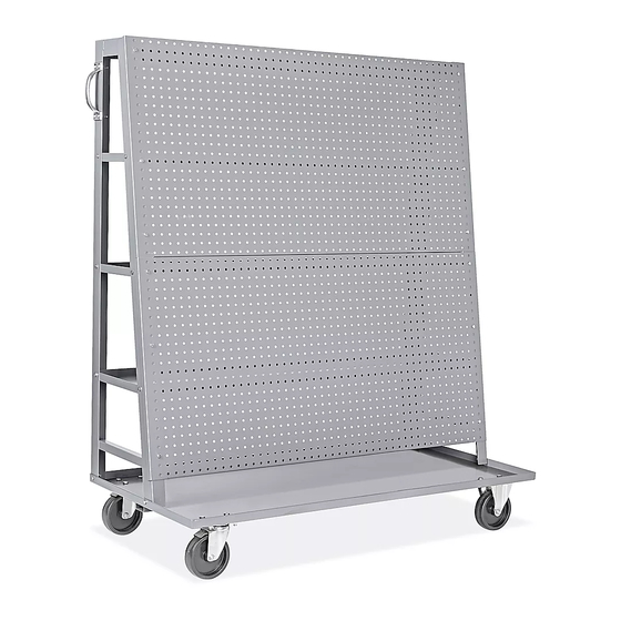
H-9013
PEGBOARD CART
WITH SHELVES
TOOLS NEEDED
8 mm Combination Wrench
10 mm Combination Wrench
12 mm Combination Wrench
14 mm Combination Wrench
•
Do not sit, climb, hang or step on hooks or holders.
•
Do not overload hooks or holders.
Deck x 1
8" Deep Shelf x 1
Long Bolt x 16
Short Bolt x 34
PAGE 1 OF 9
1-800-295-5510
uline.com
or
8 mm Socket Wrench
10 mm Socket Wrench
12 mm Socket Wrench
14 mm Socket Wrench
Support Frame x 2
10" Deep Shelf x 1
Washer x 16
M5 Flange Nut x 8
M6 Flange Nut x 34
M8 Flange Nut x 16
Figure 1
#2 Phillips Screwdriver
Two Person Assembly
Required
SAFETY
•
Do not try to assemble pegboard cart by yourself.
Use two people.
PARTS
Pegboard Panel x 2
12" Deep Shelf x 1
Phillips Head Bolt x 8
ASSEMBLY
ATTACH SUPPORT PANELS
1. Position deck on flat surface with lipped edge facing up.
Place one support panel against the inside corner of the short
side of the deck. Align holes on the bottom of the support
panel with holes in the deck lip. (See Figure 1)
2. Insert three short bolts through the holes in the deck lip.
Thread on M6 flange nuts and secure using 10 mm wrench,
but do not tighten. (See Figure 1)
3. Repeat steps 1 and 2 for second support panel.
(See Figure 1)
Para Español, vea páginas 4-6.
Pour le français, consulter les pages 7- 9.
Top Bar x 1
Handle x 2
Rigid Caster x 2
Swivel Caster
with Brake x 2
1120 IH-9013
Advertisement

Related Manuals for U-Line H-9013


Summary of Contents for U-Line H-9013
- Page 1 Para Español, vea páginas 4-6. Pour le français, consulter les pages 7- 9. H-9013 1-800-295-5510 uline.com PEGBOARD CART WITH SHELVES TOOLS NEEDED 8 mm Combination Wrench 8 mm Socket Wrench #2 Phillips Screwdriver 10 mm Combination Wrench 10 mm Socket Wrench...
- Page 2 ASSEMBLY CONTINUED ATTACH TOP BAR Figure 2 1. Place top bar between the two support panels. 2. Align holes on inside of support panels. Top Bar 3. Insert two short bolts through holes. Thread on M6 flange nuts and secure using 10 mm wrench, but do not tighten. (See Figure 2) 4.
- Page 3 ASSEMBLY CONTINUED ATTACH HANDLES Figure 5 1. Place one handle on side of one support panel. Align holes on handle with holes on support panel. (See Figure 5) 2. Insert four Phillips head bolts through holes in handle. Thread on M5 flange nuts. Secure using 8 mm wrench and #2 Phillips screwdriver, but do not tighten.
-
Page 4: Herramientas Necesarias
H-9013 800-295-5510 uline.mx CARRITO DE TABLERO PERFORADO CON REPISAS HERRAMIENTAS NECESARIAS Llave Combinada de 8 mm Llave de Dado de 8 mm Desarmador de Cruz #2 Llave Combinada de 10 mm Llave de Dado de 10 mm Llave Combinada de 12 mm... - Page 5 CONTINUACIÓN DEL ENSAMBLE FIJAR LA BARRA SUPERIOR Diagrama 2 1. Coloque la barra superior entre los dos paneles de soporte. 2. Alinee los orificios en el interior de los paneles de soporte. Barra Superior 3. Inserte dos pernos cortos a través de los orificios. Enrosque las tuercas con reborde M6 y asegure utilizando una llave de 10 mm, pero no apriete.
- Page 6 CONTINUACIÓN DEL ENSAMBLE FIJAR EL ASA Diagrama 5 1. Coloque un asa en el lateral de un panel de soporte. Alinee los orificios del asa con los del panel de soporte. (Vea Diagrama 5) 2. Inserte cuatro pernos de cabeza de cruz a través de los orificios del asa.
-
Page 7: Outils Requis
H-9013 1-800-295-5510 uline.ca CHARIOT À PANNEAU PERFORÉ AVEC TABLETTES OUTILS REQUIS Clé mixte de 8 mm Clé à douille de 8 mm Tournevis cruciforme nº 2 Clé mixte de 10 mm Clé à douille de 10 mm Clé mixte de 12 mm Clé... - Page 8 MONTAGE SUITE FIXATION DE LA BARRE SUPÉRIEURE Figure 2 1. Placez la barre supérieure entre les deux panneaux de support. Barre supérieure 2. Alignez les trous à l'intérieur des panneaux de support. 3. Insérez deux boulons courts à travers les trous. Vissez les écrous à...
- Page 9 MONTAGE SUITE FIXATION DES POIGNÉES Figure 5 1. Placez une poignée sur le côté de l'un des panneaux de support. Alignez les trous de la poignée sur les trous du panneau de support. (Voir Figure 5) 2. Insérez quatre boulons à tête cruciforme dans les trous de la poignée, puis les écrous à...
Need help?
Do you have a question about the H-9013 and is the answer not in the manual?
Questions and answers