Table of Contents
Advertisement
Quick Links
Instruction Manual
Vibrating Wire
Stressmeter
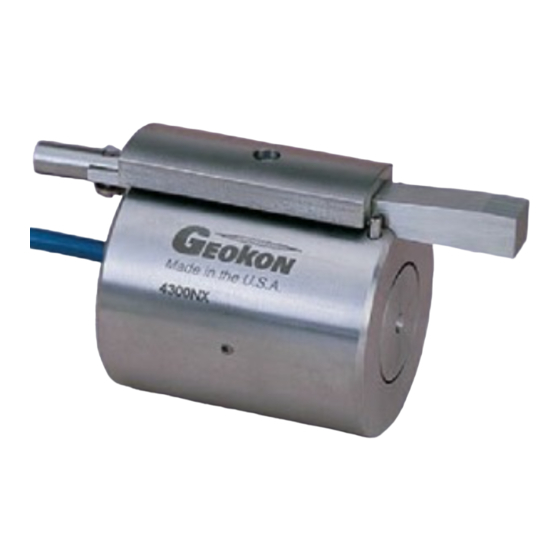
4300 Series (EX, BX, NX)
No part of this instruction manual may be reproduced, by any means, without the written consent of Geokon, Inc.
The information contained herein is believed to be accurate and reliable. However, Geokon, Inc. assumes no responsibility for
errors, omissions or misinterpretation. The information herein is subject to change without notification.
Copyright © 1984, 2004 by Geokon, Inc.
(Doc Rev C, 04/07)
Advertisement
Table of Contents

Related Manuals for Geokon Stressmeter 4300 Series


Summary of Contents for Geokon Stressmeter 4300 Series
- Page 1 4300 Series (EX, BX, NX) No part of this instruction manual may be reproduced, by any means, without the written consent of Geokon, Inc. The information contained herein is believed to be accurate and reliable. However, Geokon, Inc. assumes no responsibility for errors, omissions or misinterpretation.
- Page 3 The buyer's sole remedy for any breach of this agreement by Geokon, Inc. or any breach of any warranty by Geokon, Inc. shall not exceed the purchase price paid by the purchaser to Geokon, Inc.
-
Page 5: Table Of Contents
Contents 1. SPECIFICATIONS ............................. 1 2. THEORY OF OPERATION ..........................2 3. INSTALLATION ..............................3 3.1 B ..........................3 OREHOLE EQUIREMENTS 3.2 P ............................. 3 RELIMINARY HECKS 3.3 A ....................3 TTACHING THE EDGE LATEN SSEMBLY 3.4 S ) ..................4 ETTING THE TRESSMETER ECOVERABLE... - Page 6 LIST of FIGURES, TABLES and EQUATIONS 1. V ....................... 2 IGURE IBRATING TRESSMETER 2. V ............4 IGURE IBRATING TRESSMETER INSTALLATION TOOL ASSEMBLY 3. M 4300EX V VS. R ....8 IGURE ODEL IBRATING RESSMETER ENSITIVUTY ACTOR ODULUS 4.
-
Page 7: Specifications
1. Specifications __________________________________________________ General Specifications Nominal Range Mpa (psi) 35 - 100 (5000 - 15000) 35 - 100 (5000 - 15000) 35 - 100 (5000 - 15000) Resolution KPa (psi) 2 - 15 (0.3 - 2) 10 - 30 (1.5 - 4) 35 - 140 (5 - 20) Accuracy ±... -
Page 8: Theory Of Operation
2. Theory of Operation ____________________________________________ Geokon vibrating wire stressmeters are designed primarily for long-term measurements of stress changes in rock, by utilizing a vibrating wire transducer to measure the deformation of a thick-walled steel ring preloaded into a borehole by a wedge and platen assembly as shown in figure 1. -
Page 9: Installation
measurements, and calibration curves provided herein give sensitivity factors for materials of different moduli. It should be noted that as the rock modulus changes by a factor of 10, the gage factor changes only by a factor of 2. The stressmeter is a uniaxial device, and to completely evaluate stress changes in a given plane, three stressmeters, installed at 0°, 45°, and 90°... -
Page 10: Setting The Stressmeter (Recoverable Type)
The wedge/platen assemblies are shipped separately. They are held together by a nylon screw and nut. Remove the nut and then use the nylon screw to attach the wedge/platen assembly to the Stressmeter Body. Orient the wedge so that the narrow end is facing in the same direction as the cable, (see Figure 2). Tighten the nylon screw into the threaded hole in the body. -
Page 11: Recovering The Stressmeter
Geokon. -
Page 12: Taking Readings
4. Taking Readings ________________________________________________ 4.1 Operation of the GK-403 or GK-401 Readout Box The GK-403 or GK-401 Readout Box provides the necessary excitation and signal conditioning for the Model 4300 Series Stressmeters. To take readings, the box is connected to the gage by a jumper with either clip leads or, in the case of a terminal station, with a connector. -
Page 13: Data Reduction
The GK-404 will continue to take measurements and display the readings until the OFF button is pushed, or if enabled, when the automatic Power-Off timer shuts the GK-404 off. The GK-404 continuously monitors the status of the (2) 1.5V AA cells, and when their combined voltage drops to 2V, the message Batteries Low is displayed on the screen. - Page 14 Figure 3. Model 4300EX Vibrating Wire Sressmeter Sensitivuty Factor VS. Rock Modulus Figure 4. Model 4300BX Vibrating Wire Sressmeter Sensitivuty Factor VS. Rock Modulus...
-
Page 15: Corrections For Temperature Changes
Figure 5. Model 4300NX Vibrating Wire Sressmeter Sensitivity Factor vs. Rock Modulus 5.2 Corrections for Temperature Changes Because of the materials used in construction of the stressmeter the device is affected by changes in ambient temperature. Since these gages are normally installed underground in constant temperature environments corrections are not normally applied. -
Page 16: Environmental Factors
It should be noted that this temperature correction factor is for a gage in a free field with no restraints. In a field condition where the gage is firmly placed in a borehole the gage temperature sensitivity is also dependent on the gage/rock interactions, and these relationships are very complex and beyond the scope of this manual. - Page 17 Table 1: Thermistors ______________________________________________ Thermistor Linearization using Steinhart and Hart Log Equation Tech Memo 91-03 Doc Rev 6-94, Geokon, Inc. Thermistor Type: YSI 44005, Dale #1C3001-B3, Alpha #13A3001-B3 Basic Equation: − 273 2 A B LnR C LnR T = Temperature in °C...
-
Page 18: Appendix 1: Biaxial Stress Changes
Appendix 1: Biaxial Stress Changes ______________________________ The relationship between the radial deformation of a borehole, U, and two principle stresses in the plane of a borehole has been given by Hast (1958) and Merrill and Peterson (1961). For Plane Stress: + σ... -
Page 19: References
Example: Three gages are set in borehole. The first is at 0° (σ ), the second at 45° (σ ) and the third at 90° (σ ), measured counter-clockwise from 0. The uniaxial stress changes for each gage are determined by the reading change times the calibration factor.
Need help?
Do you have a question about the Stressmeter 4300 Series and is the answer not in the manual?
Questions and answers