
Subscribe to Our Youtube Channel
Related Manuals for mercor mcr FID S


Summary of Contents for mercor mcr FID S
- Page 1 Ul. Grzegorza z Sanoka 2 80-408 Gdańsk tel. (0-58) 341 42 45 tel./fax +48 58 341 39 85 OPERATION AND MAINTENANCE MANUAL (OMM) Fire damper type mcr FID S Version FID S 22.02.02.18 FIRE VENTILATION SYSTEMS...
-
Page 2: Table Of Contents
FID S/... p/... single-plane fire dampers TABLE OF CONTENTS: 1. INTRODUCTION ..............................3 2. SUBJECT .................................. 3 3. DEVICE INTENDED USE ............................3 4. DESIGN AND OPERATING PRINCIPLE ......................... 4 5. DEVICE IDENTIFICATION ............................8 6. INSTALLATION ................................ 8 6.1. - Page 3 FID S/... p/... single-plane fire dampers CAUTION The product should be stored and used in rooms where: • there is no access to dust, gases, caustic vapors and other aggressive chemical vapors that can destroy the insulating elements and structural elements;...
-
Page 4: Introduction
2. SUBJECT This manual concerns the entire group of single-plane fire dampers type mcr FID S/... p/..Compliance with the Manual guidelines ensures correct functioning of the device in terms of fire protection of rooms as well as safety of the system users. -
Page 5: Design And Operating Principle
Maximum surface area of type mcr FID S/… p/O dampers: 0.31 m . The minimum damper surface area is 0.01 m The single dampers in multiple fire damper sets mcr FID S/V p/P and mcr FID S/V-M p/P are produced in the following size ranges: Width: 200 to 710mm Height: 200 to 1500mm Aside from the standard dimensions, the fire dampers may also be manufactured in intermediate sizes. - Page 6 The actuator has no thermoelectric trigger. The operating principle and behaviour of the mcr FID S/... p/... single-plane dampers depend on their application versions: shut-off fire dampers –...
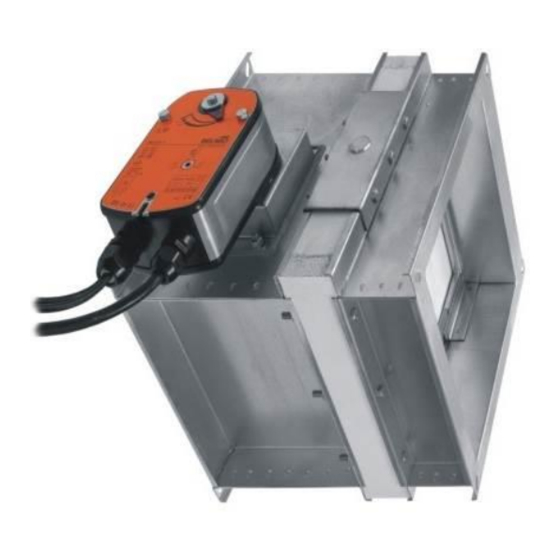
- Page 7 It is recommended that the fire damper were opened and closed when the ventilation system is turned off. Trigger control gears The following trigger control gears are available for the mcr FID S/… p/… fire dampers: Electric actuator: BF 230-T /V-M...
- Page 8 BF 24TL-ST 198 10 EXBF 225 55 75 160 * embedding border mcr FID S/… p/O fire damper with actuator Gear * embedding border mcr FID S/… p/P fire damper with RST Gear * embedding border mcr FID S/… p/O fire damper with RST...
-
Page 9: Device Identification
(multiple damper sets) The mcr FID S/... p/... fire dampers may also be installed in partitions with a lower class of fire resistance. In this case the damper fire resistance is equal to the partition fire resistance if the smoke tightness is met. When installing the “MERCOR”... -
Page 10: Pre-Assembly Inspection
Protecting the damper against buckling The mcr FID S/... p/.. fire damper will work properly if the isolation partition rotation axis is horizontal. If the fire damper must have the axis in the vertical, state this when ordering. In this case the manufacturer adds optional accessories with keep clearance between the damper body and the partition at the damper bottom. - Page 11 During the installation of the mcr FID S/... p/... fire damper mind specifically that the thermal trigger (a fusible element) must not be damaged or exposed to high temperature (from fire, and welding/soldering equipment), which might trigger it (it is a single use element and not subject to warranty replacement).
- Page 12 6 – Ventilation-grade seal X – wall thickness Installation of the mcr FID S/... p/P fire damper in concrete block or solid brick walls 1 – Ventilation duct. 2 – mcr FID S/… p/O fire damper, ØD...
- Page 13 6 – High temperature gasket M8 metal screw X – wall thickness Installation of the mcr FID S/... p/P fire damper in a floor slab, cont'd “MERCOR” SA 13/28 – The company reserves the right to modify and change the document. Version FID S 22.02.02.18...
- Page 14 3 – Cement mortar (or other as suitable) 4 – Floor slab X – wall thickness Installation of the mcr FID S/... p/O fire damper in a floor slab 1 – Ventilation duct. 4 – Cement mortar (or other as suitable) 7 – Panel wall 2 –...
- Page 15 X – wall thickness 3 – E.g. cement mortar. 6 – Structural profile Installation of the mcr FID S/... p/O fire damper in a panel wall 1 – mcr FID S/... p/P fire damper, BxH. 4 – solid wall 2 – Threaded rod 5 –...
- Page 16 3 – M10 fixing screw 6 – Eg gypsum mortar 9 -Suspension system Installation of the mcr FID S/V p/P damper in fire ventilation systems (building partitions / horizontal fire ventilation ducts) 1 – mcr FID S/V p/P BxH damper 4 –...
- Page 17 Installation of the mcr FID S/... p/P fire damper as a module (multiple damper set of 4 dampers) Other configurations of the mcr FID S /... p/P dampers modules can be made, consisting of two or more dampers, while maintaining the minimum distances between the dampers according to the drawing above “MERCOR”...
- Page 18 Installation of the FID S/V p/P or mcr FID S/V-M p/P fire damper in batteries consisting 3 single dampers. Seal the connections with fireproof silicone. Other configurations of mcr FID S/V p/P and mcr FID S/V-M p/P fire dampers sets can be made, consisting of two or three dampers, while maintaining assembly rules acc. Drawing above.
- Page 19 Modular installation of the mcr FID S/S p/P damper consisting of two or more dampers Configurations consisting of two or more mcr FID S/S p/P fire dampers with maximum dimensions of a single fire damper BxH: 1500x1105 mm are allowed, while maintaining the installation rules according to the figure above. L = 60 ÷ 200mm.
-
Page 20: Electrical Connections
Configurations consisting of two or more mcr FID S/S p/P fire dampers with maximum dimensions of a single fire damper BxH: 1500x1105 mm are allowed, while maintaining the installation rules according to the figure above. Installation of power and control mechanisms from the bottom or top of the damper. - Page 21 FID S/... p/... single-plane fire dampers Technical specifications BEE24, BEE24-ST BEE230 BEN24, BEN24-ST BEN230 AC 24V 50/60Hz AC 24V 50/60Hz AC 220-240V 50/60 Hz Power supply AC 220-240V 50/60 Hz DC 24 V DC 24V Power demand: - for spring tensioning...
- Page 22 FID S/... p/... single-plane fire dampers - motor max. 45 dB (A) max. 45 dB (A) - spring ~ 62 dB (A) ~ 62 dB (A) Connection diagram for the BF24-Tand BF230-T actuators Connection diagram for the BFL24-T, BFL230-T, BFN24-T, BFN230-T, BF24-TN and BF230-TN...
- Page 23 FID S/... p/... single-plane fire dampers Connection diagram for the BE24, BLE24, BE230 and BLE230 actuators Connection diagram for the BEE24, BEN24, BEE230 and BEN230 actuators Note: The BE and BLE actuator operating control requires a three-wire system. The actuator sense of rotation is switched by applying the supply voltage to terminal 2 or 3, depending on the desired sense.
- Page 24 FID S/... p/... single-plane fire dampers Thermal trigger EX zone EEx-e rated installation box Connection diagram for the EXBF actuators Caution: For proper operation of a device equipped with electrical actuators, it is recommended that the rated voltage housed tolerance of 24V±10% or 230V±10%.
- Page 25 FID S/... p/... single-plane fire dampers Connection diagram for transformer module type MP230/24 Caution! - The location of the limit switches is shown for the fire damper in the safety position For proper operation of a device equipped with electrical actuators, it is recommended that the rated voltage housed tolerance of 24V±2% or 230V±2%.
-
Page 26: Transport & Storage Conditions
Edges to be coated with adhesive Spacer between the isolation partition and the casing 3 – mcr FID S/... p/... fire damper 1 - Spacer Spacer between the isolation partition and the casing – installation location Caution: The manufacturer shall not be liable for any damage due to improper or inconsistent execution of the above. -
Page 27: Maintenance And Servicing
Refer all matters related to technical inspection, maintenance and servicing of this equipment to the Mercor SA Service Department, serwis@mercor.com.pl, tel. +48 58 341 42 45 ext. 170, fax: +48 58 341 39 85, from 8 AM to 4 PM (Mo-Fri). - Page 28 If the device can not be repaired at the place of its installation, "MERCOR" SA reserves the necessity of its disassembly, possible delivery to the address indicated by "MERCOR" SA and re-assembly.
Need help?
Do you have a question about the mcr FID S and is the answer not in the manual?
Questions and answers