
Subscribe to Our Youtube Channel
Related Manuals for mercor mcr S-THERM C


Summary of Contents for mercor mcr S-THERM C
- Page 1 OPERATION AND MAINTENANCE MANUAL Spot smoke exhaust vents mcr S-THERM type: C, E, NG-A Doc. no: HO.20.01324_en rev.: B of: 31.03.2021...
-
Page 2: Table Of Contents
mcr S-THERM smoke exhaust vents: C, E, NG-A. OPERATION AND MAINTENANCE MANUAL Contents INTRODUCTION ......................3 PURPOSE OF THE PRODUCT ..................3 DESIGN AND OPERATING PRINCIPLE ................4 SHIPPING AND DELIVERY ....................6 MOUNTING OF DEVICE ....................7 5.1. Assembling the steel base ....................7 5.2. -
Page 3: Introduction
This operation and maintenance documentation allows the user to get acquainted with the purpose, construction, principle of operation, proper installation and operation of mcr S-THERM C, E, and NG-A smoke exhaust vents and smoke and exhaust vents. The documentation also contains additional information on the conditions of operation, maintenance and product warranty conditions. -
Page 4: Design And Operating Principle
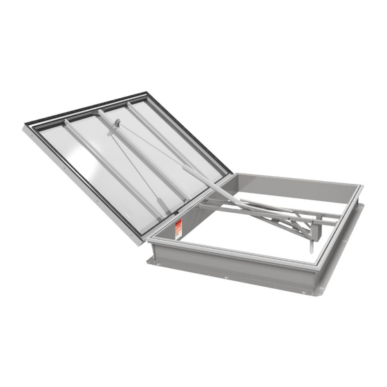
S-THERM smoke exhaust vents: C, E, NG-A. OPERATION AND MAINTENANCE MANUAL 3. DESIGN AND OPERATING PRINCIPLE Depending on the customer's individual requirements, "MERCOR" S.A. offers smoke exhaust vents on straight or slanting bases, in a wide range of opening dimensions and base height. All the steel elements are protected with hot-dip or galvanic zinc coating. - Page 5 mcr S-THERM smoke exhaust vents: C, E, NG-A. OPERATION AND MAINTENANCE MANUAL a/ type C, E leaf traverse actuator holder smoke exhaust actuator ventilation actuator (optional) hook console base base reinforcement on the hinge side base flange hinge b/ type NG-A 1.
-
Page 6: Shipping And Delivery
mcr S-THERM smoke exhaust vents: C, E, NG-A. OPERATION AND MAINTENANCE MANUAL (c) ALU sandwich panel (a) polycarbonate sheet (b) polycarbonate sheet and acrylic or polycarbonate dome Fig. 3 Typical glazing of mcr S-THERM smoke exhaust vents. 4. SHIPPING AND DELIVERY The mcr S-THERM vents type C, E, NG-A are delivered in parts;... -
Page 7: Mounting Of Device
mcr S-THERM smoke exhaust vents: C, E, NG-A. OPERATION AND MAINTENANCE MANUAL 5. MOUNTING OF DEVICE NOTE: 1. After installing the vent, it is essential to remove the protective film from the external aluminium elements of the vent (pressing frames, pressing strip) and from the vent glazing (PCA, sandwich panels, acrylic domes). - Page 8 mcr S-THERM smoke exhaust vents: C, E, NG-A. OPERATION AND MAINTENANCE MANUAL In case of installation of the mcr S-THERM vent on the roof, the base should be placed in such a way that the vent hinge is located in the lower point - in accordance with the pitch. Roof pitch Roof pitch Fig.
- Page 9 mcr S-THERM smoke exhaust vents: C, E, NG-A. OPERATION AND MAINTENANCE MANUAL Once the two sides have been put together, they can be joined using: the corner bracket acting as a lock, the bottom fastener (optional element) and rivets: rivet punch advance rivet...
-
Page 10: Mounting The Base To The Structure
mcr S-THERM smoke exhaust vents: C, E, NG-A. OPERATION AND MAINTENANCE MANUAL 5.2. Mounting the base to the structure NOTE: before attaching all sides to the structure, the lengths of the diagonals and the angles in the corners of the bases must be verified and corrected if necessary! Vents should be placed on the structural elements of the roof - such as: purlins, trimmers, roof structure sheet, reinforced concrete plinth. -
Page 11: Method Of Positioning The Bases
mcr S-THERM smoke exhaust vents: C, E, NG-A. OPERATION AND MAINTENANCE MANUAL 5.3. Method of positioning the bases Detail A Detail B Fig. 12 Positioning of the steel base on the roof (detail B) and the method of rolling up the roofing felt or membrane (detail A) detail A Steel base Thermal insulation... - Page 12 mcr S-THERM smoke exhaust vents: C, E, NG-A. OPERATION AND MAINTENANCE MANUAL Steel base Thermal insulation of the base Aluminium frameframe Roofing paper Traverse of the opening system Leaf gasket Support frame Pressing frame Leaf glazing 10. Pressing skirting board (recommended item) Fig.
- Page 13 mcr S-THERM smoke exhaust vents: C, E, NG-A. OPERATION AND MAINTENANCE MANUAL 1. Steel base of vent 2. Thermal insulation of the base 3. Membrane or roofing paper 4. Roof thermal insulation 5. Trapezoidal sheet 6. Additional roofing flashing 7. Load-bearing steel structure Fig.
-
Page 14: Mounting Of Soft Body Impact Safety Nets For An Impact Energy Of 1200 J
mcr S-THERM smoke exhaust vents: C, E, NG-A. OPERATION AND MAINTENANCE MANUAL 1. Diagonal steel base of vent 2. Thermal insulation of the base 3. Membrane or roofing paper 4. Roof thermal insulation 5. Trapezoidal sheet 6. Load-bearing steel structure Fig. - Page 15 mcr S-THERM smoke exhaust vents: C, E, NG-A. OPERATION AND MAINTENANCE MANUAL For a correct installation of the nets, please use Table HO.20.01868, where the spacing (L1, L2 and Ld - only for split grids) of the consoles that fix the standard grids to the B sides of the base are marked. In the initial phase of installation, each console should be fixed to the base using a single self-drilling screw 6.3x19: 1.
- Page 16 mcr S-THERM smoke exhaust vents: C, E, NG-A. OPERATION AND MAINTENANCE MANUAL The installation process of the temporary net should begin by attaching the temporary net console to each of the centre consoles with a single 6.3x19 self-drilling screw: 1. Standard net console 2.
-
Page 17: Mounting The Frame To The Base
mcr S-THERM smoke exhaust vents: C, E, NG-A. OPERATION AND MAINTENANCE MANUAL 5.5. Mounting the frame to the base After the base has been placed, insulated and protected with roofing paper or membrane, put the frameframe with a PES 20x5 (factory mounted) gasket on top of it. Make sure that the hinge side of the frameframe is on the hinge side (with reinforcements) of the base: 1. - Page 18 mcr S-THERM smoke exhaust vents: C, E, NG-A. OPERATION AND MAINTENANCE MANUAL NOTE: when assembling the frameframer, pay special attention to the correct setting of your power screwdriver parameters! Fig. 29 Mounting the frame to the base and correct installation parameters. NOTE: Only a properly tightened washer guarantees a tight connection! Fig.
-
Page 19: Assembly Of The Opening System
mcr S-THERM smoke exhaust vents: C, E, NG-A. OPERATION AND MAINTENANCE MANUAL 5.6. Assembly of the opening system NOTE: Before installing the opening system, the temporary net (if already installed) and the temporary consoles must be removed in reverse order to the steps described on page 16. The opening system must be placed in the axis of the smoke exhaust vent: Hinge axis Axis of the... -
Page 20: Mounting Of Leaf
mcr S-THERM smoke exhaust vents: C, E, NG-A. OPERATION AND MAINTENANCE MANUAL 5.7. Mounting of leaf NOTE: any elements that may cause a collision with the vent leaf in its full range of motion should be removed before installation! Place the leaf on the base frame symmetrically, taking care that the hinge elements are correctly positioned. - Page 21 mcr S-THERM smoke exhaust vents: C, E, NG-A. OPERATION AND MAINTENANCE MANUAL Correctly prepared elements can be assembled without tools; however, in case of trouble with applying the insert, the assembly can be facilitated by gently squeezing both parts of the hinge using, for example, a carpenter clamp grip with plastic tips: Fig.
-
Page 22: Fastening The Opening System To The Leaf
mcr S-THERM smoke exhaust vents: C, E, NG-A. OPERATION AND MAINTENANCE MANUAL 5.8. Fastening the opening system to the leaf Connect the actuator to the hook console mounted in the vent leaf. To do so, remove the pin and pull the lower pin out of the hook console. - Page 23 mcr S-THERM smoke exhaust vents: C, E, NG-A. OPERATION AND MAINTENANCE MANUAL Pressing frame Dome Multi-chamber PES gasket polycarbonate Sheet metal screw 5.5x32 with EPDM washer Support frame Fig. 38 Flap leaf cross-section - PES gasket between glazing and on the leaf supporting frame. Page 23 of 41...
-
Page 24: Wind Deflectors And Inlet Deflectors
mcr S-THERM smoke exhaust vents: C, E, NG-A. OPERATION AND MAINTENANCE MANUAL 6. WIND DEFLECTORS AND INLET DEFLECTORS 6.1. Wind deflectors Wind deflectors are used to increase the active surface of smoke exhaust vents. In the standard version they are made of aluminium sheet. Wind deflectors are delivered in bulk - arranged on a pallet for convenient storage and transportation. - Page 25 mcr S-THERM smoke exhaust vents: C, E, NG-A. OPERATION AND MAINTENANCE MANUAL Wind deflector Smoke exhaust vent base with frame Mounting bracket - place of riveting the wind deflectors Notches facilitating the manual folding of the wind deflector Stiffening rib (in selected sizes) Fig.
-
Page 26: Inlet Deflector
mcr S-THERM smoke exhaust vents: C, E, NG-A. OPERATION AND MAINTENANCE MANUAL 6.2. Inlet deflector The inlet deflector is used to increase the effective aerodynamic efficiency of vent types C and E, i.e. the smoke exhaust area. The inlet deflector is mounted at the bottom of the vent base. It is made of galvanized steel sheet, or alternatively aluminium sheet, and can be painted in any RAL colour. -
Page 27: Flap Leaf Adjustment
mcr S-THERM smoke exhaust vents: C, E, NG-A. OPERATION AND MAINTENANCE MANUAL 7. FLAP LEAF ADJUSTMENT (HOOK CONSOLE, EYEBOLTS AND 'T' BOLTS) The vent leaf is connected to the actuator via a hook console. The hook console is locked to the T-bolt. The pneumatic and electric spindle actuators are connected to the hook console by an eyebolt that is screwed into the piston rod/spindle of the actuator. -
Page 28: Control
mcr S-THERM smoke exhaust vents: C, E, NG-A. OPERATION AND MAINTENANCE MANUAL 8. CONTROL The operation of smoke and combined smoke exhaust and ventilation vents is based on devices used to open and close them. These devices constitute the control system for smoke exhaust or smoke exhaust and ventilation. - Page 29 mcr S-THERM smoke exhaust vents: C, E, NG-A. OPERATION AND MAINTENANCE MANUAL Cable Clamping collar Sleeve (for plastic lines) Body Fig. 51Method of installing the flexible pneumatic lines. Copper tube Clamping collar Body Fig. 52 Connection of the screw connection to the copper/steel pipe. NOTE: For safety reasons during transport, the thermal fuse in the vent is not armed.
-
Page 30: Electric Control
mcr S-THERM smoke exhaust vents: C, E, NG-A. OPERATION AND MAINTENANCE MANUAL Fig. 54 PUAV pneumatic actuator - lock release direction. Pneumatic actuators for smoke exhaust purposes are equipped with an internal lock which prevents closing of the fully opened vent leaf. Method of closing the vent leaves after an alarm opening for systems without remote closing function: - Release the CO from the system by unscrewing the cartridge from the thermal fuse or alarm box... - Page 31 mcr S-THERM smoke exhaust vents: C, E, NG-A. OPERATION AND MAINTENANCE MANUAL For transport reasons, the electric ventilation actuator is usually not installed at the factory. It must be installed in the console of the opening system using LB 18-2-SL13 bushing and M5x16 bolts (for E4-xxx- 230 actuator) or ST 12-1/8 bolt (for Exxx-230 actuator) or threaded pins (JMBB actuators) supplied with the actuator.
-
Page 32: Mechanic Control
mcr S-THERM smoke exhaust vents: C, E, NG-A. OPERATION AND MAINTENANCE MANUAL 8.4. Mechanic control The mechanic control system consists of a lock and oleopneumatic actuators (gas springs) connected by a lever to the traverse in the base and to the leaf. There are 3 types of lock: 1) Standard (without electromagnet). -
Page 33: Preparing The Lock For Operation
mcr S-THERM smoke exhaust vents: C, E, NG-A. OPERATION AND MAINTENANCE MANUAL 1. Fuse 2. Electromagnet 3. Rope Fig. 63Methods of opening the lock. 8.4.2. Preparing the lock for operation The vent is delivered to the customer with the lock secured with a tie strap - applies only to locks equipped with an electromagnet. - Page 34 mcr S-THERM smoke exhaust vents: C, E, NG-A. OPERATION AND MAINTENANCE MANUAL After installing the vent in its final location and before using it, the lock must be released from its shipping protection. To do this, first remove the lock housing by loosening the bolts holding the housing on.
- Page 35 mcr S-THERM smoke exhaust vents: C, E, NG-A. OPERATION AND MAINTENANCE MANUAL 1. Electromagnetic jumper Fig. 66 Closing the lock jumper. a) Lock “nut" open Lock “nut" closed 2. Lock “nut” 3. Closed catch 4. Lock lever in closed position Fig.
-
Page 36: Lock Adjustment
mcr S-THERM smoke exhaust vents: C, E, NG-A. OPERATION AND MAINTENANCE MANUAL 8.4.3. Lock adjustment The lock is adjusted by determining the height at which it is mounted. The screws which fix the lock and at the same time are responsible for the adjustment are presented on Fig. 65 - marked with the number "2". -
Page 37: Initial Start-Up
For electric control - measure voltage value of actuator supply line. b) For pneumatic control - verify the value of supply pressure or the size of CO cartridge used. If necessary, contact the Service Department of "MERCOR" S.A. Fig. 69 Location of the nameplate. Page 37 of 41... -
Page 38: Servicing And Maintenance
Damage to the vents caused in this way does not constitute grounds for complaint. In matters related to technical inspections, maintenance and servicing of the equipment, please contact the local representatives of "MERCOR" S.A. or Service Department at phone: 58/ 341 42 45ext1998 a.m. - 4 p.m., e-mail: claim@mercor.com.pl. -
Page 39: Warranty Terms -_ Do Podmiany Z Plikem Warranty Terms_2022
S.A. shall remove them within 21 days of the written notification, subject to paragraph 5. 5. “MERCOR” S.A. reserves the right to lengthen the repair time in the event of complicated repairs or those that require non-standard sub-assemblies [elements] or spare parts to be purchased. - Page 40 S-THERM smoke exhaust vents: C, E, NG-A. OPERATION AND MAINTENANCE MANUAL Maintenance or periodic servicing are not done in due time or are performed by unauthorized persons or a service center not authorized by “MERCOR” S.A., or the equipment is operated in the wrong way, ...
-
Page 41: Certificate Of Constancy Of Performance
mcr S-THERM smoke exhaust vents: C, E, NG-A. OPERATION AND MAINTENANCE MANUAL 12. CERTIFICATE OF CONSTANCY OF PERFORMANCE Page 41 of 41...
Need help?
Do you have a question about the mcr S-THERM C and is the answer not in the manual?
Questions and answers